
Related Manuals for Barco R92112011


Summary of Contents for Barco R92112011
-
Page 1: User Guide
SIM 7Q series User Guide R92112011 R92112012 R92112013 R92112021 R92112022 R92112023 R92112161 R92112162 R92112163 R9211222 R9211224 R59770066/12 08/12/2014... - Page 2 Factory: Barco nv Advanced Visualization Systems Noordlaan 5, B-8520 Kuurne Phone: +32 56.36.82.11 Fax: +32 56.36.84.86 Support: www.barco.com/esupport Visit us at the web: www.barco.com Printed in Belgium...
-
Page 3: Software License Agreement
The period of guarantee begins on the date of transfer of risks, in the case of special systems and software on the date of commissioning, at latest 30 days after the transfer of risks. In the event of justified notice of complaint, Barco can repair the fault or provide a replacement at its own discretion within an appropriate period. - Page 4 GNU-GPL code If you would like a copy of the GPL source code contained in this product shipped to you on CD, please contact Barco. The cost of preparing and mailing a CD will be charged.
-
Page 5: Table Of Contents
Table of contents TABLE OF CONTENTS 1. Introduction ......................5 About the projector . - Page 6 Table of contents 7.4.4 Save as (create a custom file) ....................65 7.4.5 Rename file .
- Page 7 Table of contents 7.8.11 Gray Level Definition......................144 7.8.11.1 Description.
- Page 8 Table of contents R59770066 SIM 7Q SERIES 08/12/2014...
-
Page 9: Introduction
For the latest version of the product manuals, see http://www.barco.com. Clarification of the term “SIM 7Q series” used in this document When referring in this document to the term “SIM 7Q series” it is meant that the content is applicable for the following Barco products: •... -
Page 10: Racu Hand Held Control Unit
1. Introduction Related documentation Several advanced adjustments can be set and controlled via the Barco hand held remote control unit xRACU and are covered in the dedicated System manual. Image 1-2 RACU hand held control unit Symbol overview The following icons are used in the manual :... -
Page 11: Packaging
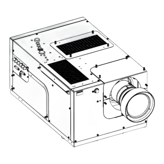
2. Packaging 2. PACKAGING Overview • Unpacking Unpacking CEE7/7 European power plug to connect the power cord to the wall outlet. NEMA5 American power plug to connect the power cord to the wall outlet. Content Description Quantity SIM 7 projector Remote Control Unit (RCU) + batteries Power cord CEE7 Power cord NEMA5... - Page 12 Always remove the lens before transporting the projector. AUTION Make sure that the projection lens has the one-to-one match with the projector and please contact Barco in case of replacement of the projection lens. How to unpack the projector ? 1. Release the cord straps.
-
Page 13: Unpacking The Cardboard Box: Exploded View
2. Packaging foam parts inner box projector manuals power cords small box outer box projection lens small box Image 2-3 Unpacking the cardboard box: exploded view Retain the original shipping cardboard boxes and packing material. It will be needed if you ever have to ship the projector. - Page 14 2. Packaging R59770066 SIM 7Q SERIES 08/12/2014...
-
Page 15: Installation Guidelines
3. Installation guidelines 3. INSTALLATION GUIDELINES Overview • Safety warnings • Installation guidelines Safety warnings ARNING Before installing the projector, first read the safety instructions in the safety manual (R5975258) delivered with the projector. Insure that the room can be easily evacuated in case of a lamp explosion. Mercury vapor warnings Keep the following warnings in mind when using the projector. -
Page 16: What About Ambient Light
filters as this will dramatically reduce the lifetime of the consumables. It is advised to replace the air filters at any lamp change. Barco reserves itself the right to refuse warranty replacement of consumables if they have been used in a projector with dirty air filters. -
Page 17: Installation
4. Installation 4. INSTALLATION Overview • Dimensions • Fixation points at the bottom of the projector • Projector tilt • RCU battery installation • Lens installation • Projector configuration • Connections Dimensions Projector dimensions and weight Dimensions are given in mm and inch (1inch = 25.4 mm) Weight (without lens) : approx. -
Page 18: Fixation Points At The Bottom Of The Projector
4. Installation FRONT VIEW BOTTOM VIEW LEFT SIDE VIEW air exhaust BACK VIEW air filter air filter TOP VIEW Image 4-1 Dimensions Fixation points at the bottom of the projector Describing the fixation points To fix the projector to its support, three bolts can be screwed into the threaded holes at the bottom of the projector. The bolts must meet the following specifications: •... -
Page 19: Projector Tilt
4. Installation Image 4-2 Fixation points Projector tilt AUTION Not respecting the projector tilt range will cause lamp flicker or even lamp explosion. Tilt range The tilt range of the projector is restricted by the tilt range of the lamp. The drawings below show the maximal tilt range in both senses. -
Page 20: Rcu Battery Installation
4. Installation 360° Image 4-4 Projector tilt range RCU battery installation Where to find the batteries for the remote control ? The batteries are not placed in the remote control unit to avoid control operation in its package, resulting in a shorter battery life time. -
Page 21: Lens Installation
4. Installation Image 4-7 AUTION Replace with the correct battery type. Use two AA size batteries. There is a risk of explosion if the battery is replaced with an incorrect type. AUTION Replace the battery as explained above. There is a risk of explosion if the battery is incorrectly installed. -
Page 22: Shift Capabilities
4. Installation Ref. Image 4-8 Projection Distance (PD) and Screen Width (SW) Screen width The Screen Width or SW is the total width of the image as it is projected on the screen, expressed in meter or inch. Formulas Lens Zoom status Metric formulas (meter) Inch formulas (inch) -
Page 23: Lens Shift: Maximum Horizontal Shift (Vertical Shift = Maximum = 100%)
4. Installation -20% +20% +100% -100% +20% -20% Image 4-10 Lens shift: maximum horizontal shift (vertical shift = maximum = 100%) -20% +20% +100% -70% +70% -100% -20% +20% Image 4-11 Lens shift: range The best image quality is obtained in nominal lens position (i.e. 0% shift). Shifting the image to the limit of its range starts introducing some falloff. -
Page 24: Installing The Lens And Adjusting The Scheimpflug
4. Installation Horizontal shift in nominal position Horizontal shift : -70% Projector Projector Screen Screen Image 4-12 Vertical shift in nominal position Vertical shift : +100% Vertical shift : -100 % Projector Projector Projector Screen Screen Screen Image 4-13 4.5.4 Installing the lens and adjusting the Scheimpflug ARNING In case of a projector with NVG option, do not insert your fingers in the lens holder if the lens is... -
Page 25: Screws To Lock The Lens Scheimpflug Settings (Left Side)
4. Installation Back focal length adjustment is also needed after the projection lens installation. See "Back focal length adjustment", page 42 for detailed procedure. Necessary tools • Torx screwdriver T10 • Nut spanner or socket spanner 10 mm • Allen key 2 mm How to prepare the projector lens? 1. -
Page 26: Bottom Lens Cover: Fixing Screws
4. Installation Image 4-18 Bottom lens cover: fixing screws 3. Remove the lock nuts and washers from the lens holder studs, but leave the springs on the lens holder studs Image 4-19 Lens: scheimpflug springs 4. Slide the lens over the 3 studs Image 4-20 Lens positioned 5. -
Page 27: Connecting The Lens
4. Installation Image 4-21 Lens fixation nuts 6. Fix the lock nuts until the lens flange touches the lens holder plate at the 3 fixation points (nominal position). 7. Unscrew each lock nut 1 revolution and start adjusting the Scheimpflug by tightening or loosening these lock nuts 8. -
Page 28: Lens Data
4. Installation How to connect the lens ? 1. Connect the male connector attached to the lens to the female connector located on the front of the projector Tip: The side labeled TOP on the male connector must be oriented upwards. Image 4-24 Projector lens connection 2. -
Page 29: Projector Configuration
4. Installation Also see the lens connection procedure. Projector configuration The different configurations Depending on the installation the projector can be mounted in different ways, the 4 different configurations are: Rear/Ceiling Rear/Table Front/Ceiling Front/Table Image 4-26 Projector configurations Connections Overview •... -
Page 30: Signal Connections
4. Installation Image 4-27 Barco SIM7 Power connection 3. Secure the connection with the locking spring. OPEN CLOSED Image 4-28 AUTION To prevent damage to the projector always ensure that the locking spring is well engaged ! 4.7.2 Signal connections Overview •... -
Page 31: Input Section
4. Installation 4.7.2.1 Input section Overview The input section consists of 2 input layers and a communication layer: • input layer 1: twin dual link DVI input • input layer 2: analog input consisting of a 5 BNC RGBHV input, a composite video input (not supported) and a S-Video input (not supported) •... -
Page 32: Connecting A Dvi Source
4. Installation R / PR G / Y B / PB Hs / Cs VIDEO S-VIDEO Image 4-32 Video input board 4.7.2.3 Connecting a DVI source How to connect two single channel DVI sources ? 1. Connect each source to the projector by connecting the DVI male connector of channel 1 into the projector’s DVI 1 female input connector and the DVI male connector of channel 2 in the DVI 2 female input connector Image 4-33 Connections : connecting 2 DVI sources... -
Page 33: Connecting An Rgb Source
4. Installation Channel 1 Channel 2 Image 4-34 Connections : connecting a dual channel DVI source 4.7.2.4 Connecting an RGB source How to connect the RGB input ? 1. Connect the 4 or 5 BNC cables to the projector’s 5-cable input. Image 4-35 Connections : connecting an RGB source R59770066 SIM 7Q SERIES 08/12/2014... -
Page 34: Communication
4. Installation 4.7.3 Communication Overview • Network connections • Network settings 4.7.3.1 Network connections What can be done ? The projector can be connected to a network allowing it to be accessed from any connected network device. The Ethernet connection can be used to upload/download projector software and/or to set up communication (TCP-packets) with the projector. -
Page 35: Network Settings
4. Installation To LAN Image 4-37 Network connection through a HUB See Network settings to set the communication port. 4.7.3.2 Network settings AUTION Make sure that a DHCP server is available in the network and works fine. In normal conditions, the network detection takes few seconds. This means that the total time needed to go from power ON to Standby mode is only a few seconds. - Page 36 4. Installation DHCP DHCP setting: • Yes: The projector will dynamically obtain its IP address from the DHCP server. • No: The IP address needs to be entered manually. Note that when selecting Fixed IP the IP settings fields are enabled IP Address Fixed IP Address of the projector : this field can be edited when Fixed IP is selected Subnet Mask...
- Page 37 4. Installation 7. Press Apply settings to apply the changes A dialog box is shown. The different executed operations are shown with a checkbox. The last operation Restarting network takes a few seconds more. Image 4-40 R59770066 SIM 7Q SERIES 08/12/2014...
- Page 38 4. Installation R59770066 SIM 7Q SERIES 08/12/2014...
-
Page 39: Setup
5. Setup 5. SETUP Overview • Warranty: continuous mode / automatic shutdown mode • Powering the SIM 7 projector • Setting the RCU address • Starting the projector • Setting the projector address (only if necessary) • Setting the orientation •... -
Page 40: Setting The Rcu Address
5. Setup Image 5-1 Barco SIM7 : Power switch L3 and L1 light up red. After the initialization period L1 turns off. Image 5-3 Standby state : L3 is red Image 5-2 Setting the RCU address What has to be done ? To allow the communication between the RCU and the projector the RCU has to be programmed with the same address as the projector. -
Page 41: Starting The Projector
5. Setup M E N T E R U SE O G O Image 5-4 All the LED’s (3) on the top cover of the projector go out. Then LED1 starts blinking green the number of hundreds. After that LED2 starts blinking the number of tens. Finally LED3 starts blinking green the number of units. -
Page 42: Setting The Projector Address (Only If Necessary)
5. Setup If the address setting is wrong the projector will not respond to the RCU, see the next step to set the address. Setting the projector address (only if necessary) What can be done ? The projector is shipped with projector address set to ”0” In some cases the projector address must be changed, for example if an unique RCU is used to control 2 or more projectors (inde- pendently). -
Page 43: Setting The Orientation
5. Setup Setting the orientation What must be done ? Depending on the mechanical orientation of the projector (see Projector configuration in the Installation section), the projector’s internal settings have to be adapted. The projector is shipped (default) with a table/front orientation. How to set the orientation ? 1. -
Page 44: Lens Top Cover: Fixing Screws
5. Setup Necessary tools • Torx screwdriver T10 • Allen key 2 mm (hexadecimal key) • Allen key 3 mm (hexadecimal key) How to lock the lens holder? 1. Make sure the lens is in the correct position 2. Remove the top lens cover Image 5-9 Lens top cover: fixing screws 3. -
Page 45: Locking / Unlocking The Zoom Ring And The Focus Ring Of The Lens
5. Setup 5. Block the vertical shift by tightening the bolt which can be reached through the small slot at the left side of the projector (seen from the rear of it) Image 5-13 Fixation screw for vertical lens shift locking system 6. -
Page 46: Back Focal Length Adjustment
5. Setup Image 5-14 Engaging the zoom/focus locking system How to unlock the zoom ring and the focus ring of the lens? Both zoom ring and focus ring are unlocked at the same time. 1. Release (i.e. counterclockwise) the zoom/focus locking knob until no resistance is felt anymore Image 5-15 Unlocking the zoom/focus locking system 2. -
Page 47: Back Focal Length Adjustment
5. Setup Image 5-16 Back Focal length adjustment. Locking screws Adjustment hole Image 5-17 A wrong back focal length adjustment will not allow optimal focus throughout the full zoom range. Necessary tools • BFL adjustment tool • Allen key 2.5 mm (hexagonal key) How to adjust ? 1. -
Page 48: Back Focal Length: Fixation Screws
5. Setup Image 5-18 Back focal length: fixation screws Note: The fourth screw is located underneath the lens 2. Put the BFL tool in the adjustment hole Image 5-19 Back focal length adjustment tool 3. Zoom the lens to wide position 4. -
Page 49: Adjusting The Lens
5. Setup 7. Repeat step 3 to step 6 until the image stays in focus regardless to the zoom position 8. Fix the 4 screws 5.7.4 Adjusting the lens Description The shift adjustment is done during the Installation phase. The other adjustments possible on the lenses are: •... - Page 50 5. Setup Image 5-22 5. Press ENTER A text box appears on the screen, follow the instructions. Image 5-24 Image 5-23 6. Use the keys on the RCU to perform the desired action M E N T E R U SE O G O Image 5-25 How to adjust the zoom / focus using the OSD?
- Page 51 5. Setup Image 5-26 5. Press ENTER A text box appears on the screen, follow the instructions. Image 5-27 6. Use the keys on the RCU to perform the desired action M E N T E R U SE O G O Image 5-28 The use of a sheet of paper held in front of the screen can be useful to determine the focus plane (position for best focus)
- Page 52 5. Setup R59770066 SIM 7Q SERIES 08/12/2014...
-
Page 53: Getting Started
6. Getting started 6. GETTING STARTED Overview • Starting up the projector • Selecting a source • Adjusting the image • Switching the projector to standby Starting up the projector How to start up the projectors via the RCU ? 1. -
Page 54: Adjusting The Image
6. Getting started Adjusting the image How to adjust the image ? 1. Use the Image setting buttons on the RCU AUTO IMAGE O IMAGE DIGI DIGI ZOOM ZOOM PHASE PHASE IQ-PC IQ-PC TINT TINT Fire W Fire Wire ire COLOR COLOR VIDEO... -
Page 55: Advanced
7. Advanced 7. ADVANCED Overview • Using the Dialog boxes • Source selection • Image • Image files • Geometry • Lamp • General • Display setup • Installation Using the Dialog boxes How to use the dialog boxes ? Some parameters are modified by means of a dialog box, where selections can be made and/or values can be entered. -
Page 56: Source Selection
7. Advanced In some cases an alphanumeric value (file name, ...) has to be entered. Use ↑ or ↓ to scroll through the char- acter values once the input field is activated. Following characters can be browsed in this particular order: Decimal scroll list: 0123456789 Signed decimal scroll list: 0123456789- ASCII scrolllist:ABCDEFGHIJKLMNOPQRSTUVWXYZ0123456789+-*/&@#.;.abcdefghijklmnopqrstuvwxyz... -
Page 57: Image
7. Advanced Image 7-4 5. Press ENTER to confirm your choice A bullet indicates the selected source which now appears on the screen. Adjustments on an RGB signal The projector allows different adjustments on an RGB signal : • Contrast •... -
Page 58: Image Settings
7. Advanced 7.3.2 Image settings Overview • Setting the Contrast • Setting the Brightness • Gamma • Phase (RGB signals only) 7.3.2.1 Setting the Contrast Contrast adjustments Adjust the contrast to “brighten” the white parts of the image. It is recommended to adjust the brightness before adjusting the contrast. How to change the Contrast 1. -
Page 59: Gamma
7. Advanced On the screen appears now a slider box Image 7-7 8. Use ←or → , the numeric keys on the remote, or the keypad to change the brightness 7.3.2.3 Gamma Gamma adjustment The gamma parameter determines the way your encoded (luminance) signal is transformed into brightness at the output of the pro- jector. -
Page 60: Scaling
7. Advanced On the screen appears now a slider box Image 7-9 8. Use ←or → , the numeric keys on the remote, or the keypad to change the Phase 7.3.3 Scaling What can be done? The scaling of the source image can be chosen from three presets. Depending on the setting, the source signal will be displayed in a different size and will possibly be stretched in one way or another. -
Page 61: Input Balance (Rgb Signals Only)
7. Advanced In a first phase, the dimming will be (mainly) done by the ECR (Enhanced Contrast Ratio) When the ECR is at its minimum value, the CCD (Constant Contrast Dimmer) starts further dimming the light output until it is 0 For the High Contrast (HC) versions, the minimum ECR value is calibrated in the projector to coincide with a lens aperture of approximately f/6.4, which leaves a light transmission of around 25%. - Page 62 7. Advanced 0.7V Black level Image 7-13 Δ G ΔΒ Δ R Black level Image 7-14 The objective of input balancing The objective in input balancing is to “set” the same black level and the same white level for the three colors of a particular input source.
-
Page 63: Performing Black Input Balance
7. Advanced An alternative to a full screen white/black pattern is a black-and-white checkerboard pattern where the white blocks will be used for white balance and the black blocks for black balance. Image 7-16 How to set Automatic Black level ? 1. - Page 64 7. Advanced Image 7-18 8. Press ENTER A dialog box is displayed 9. Adjust the red black level on a minimal value Image 7-19 10.Adjust the blue black level to a minimal value Note: this minimal value is not necessary , provided that the 2 other colors are not influencing too much the color to be adjusted, in fact the aim is to minimize the effect of the two other colors since there is a risk of reaching too soon the transition (bright spots) due to the contribution of these two other colors signals.
-
Page 65: Image Files
7. Advanced Image 7-20 8. Press ENTER A dialog box is displayed 9. Adjust the red white level (gain) on a minimal value Image 7-21 10.Adjust the blue white level (gain) to a minimal value Note: this minimal value is not necessary , provided that the 2 other colors are not influencing too much the color to be adjusted, in fact the aim is to minimize the effect of the two other colors since there is a risk of reaching too soon the transition (bright spots) due to the contribution of these two other colors signals. -
Page 66: Load File
7. Advanced 7.4.1 Load file When to load a file ? In some cases the user wants a particular file to be used for the display of a particular source. In this case the user should load the desired file from the image files menu. The load file option will allow the user to choose between several files corresponding more or less to the active source specifications. -
Page 67: Auto Image
7. Advanced 7.4.2 Auto Image What can be done ? Auto Image creates the best suited image file for the connected source. It calculates/measures several source parameters : • Total pixels per line • Start pixel • Phase • Contrast/Brightness levels Auto Image only works for data images. - Page 68 7. Advanced In this case a DVI source is used. A DVI source does not need any image file setting. All the fields are therefore greyed out. See the dialog box below. How to edit a file ? 1. Press MENU to activate the Tool bar 2.
-
Page 69: Save As (Create A Custom File)
7. Advanced Image 7-27 • Color space : allows to select between 5 different color spaces ITU_BT_709 SMPTE_240M ITU_BT_601 • Clamp position : allows to set the clamp pulse position in the clamping circuit • Clamp width : allows to set the width of clamp pulse in the clamping circuit It is recommended to use the default values. -
Page 70: Rename File
7. Advanced Image 7-30 5. Press ENTER A dialog box is displayed Use ←or →, ↓ or ↑ the numeric keys on the remote, or the keypad to edit and change the file name, confirm with ENTER. Image 7-31 7.4.5 Rename file How to rename a file ? 1. -
Page 71: Copy
7. Advanced Image 7-33 7.4.6 Copy Copy a file The copy function allows to copy a file (standard or custom) to a custom file (to the custom directory). How to copy a file ? 1. Press MENU to activate the Tool bar 2. -
Page 72: Delete
7. Advanced 6. Use ↑ or ↓ to select the file to be copied 7. Press ENTER The file name is copied in the edit field 8. Use the keys on the remote to change the name of the destination file 7.4.7 Delete How to delete a file ? -
Page 73: Geometry
7. Advanced 5. Press → to open the menu 6. Use ↑ or ↓ to select the desired layer (for example Layer 1) 7. Use ↑ or ↓ to select the desired input (for example Data on BNC) Image 7-38 Note: Inputs that are not hardware compatible with this layer are greyed out. -
Page 74: Geometry Files
7. Advanced 7.5.2 Geometry files Description A geometry file contains the geometry corrections. The projector’s memory contains a list of files created for demo purposes e.g. to demonstrate the warping capabilities of the projector. These files are called standard files. The active file can always be edited in order to fit exactly the screen shape. -
Page 75: The Screen Is Divided In 33X33 Regions
7. Advanced 11 12 13 14 15 16 17 18 19 20 21 22 Image 7-41 The screen is divided in 33x33 regions Modes and Levels The geometry adjustment is divided in 6 groups or modes : • • • •... -
Page 76: Geometry Levels
7. Advanced Image 7-42 Geometry levels Level Hierarchy The fact that the adjustment affects other points means that a certain hierarchy must be respected when adjusting the geometry. The hierarchy or levels are indicated in the following image R59770066 SIM 7Q SERIES 08/12/2014... -
Page 77: Load
7. Advanced Level 1 Level 2 Level 3 Level 4 Level 5 Level 6 Level 7 Level 8 Level 9 Level 10 Level 11 Level 12 Level 13 17x17 Level 14 Level 15 Level 16 Level 17 Level 18 33x33 Level 19 Level 20 Level 21... -
Page 78: Edit
7. Advanced 5. Press ENTER A dialog box is displayed Image 7-44 6. Use the cursor key ↑ and ↓ to select the desired geometry file 7. Press ENTER Tip: When starting a new geometry setup it is advised to select the “No_Distortion” file. The file is loaded and the geometry settings are adapted. -
Page 79: Geometry Edit Wizard
7. Advanced Image 7-45 7.5.6.2 Geometry Edit wizard The geometry wizard When entering the Edit mode, the Edit dialog box is displayed. When selecting a point in a certain adjustment, a yellow box shows the selection and a blue dotted box is placed around the selected grid point, indicating the interaction zone. Image 7-46 R59770066 SIM 7Q SERIES 08/12/2014... - Page 80 7. Advanced Image 7-47 Note that the dialog box is transparent so as to allow the preview of the adjustment over the whole screen during the adjustment (the image to be adjusted is not hidden by the dialog box) Description of the Edit dialog box An intuitive user interface is used to perform all the geometry corrections.
-
Page 81: Geometry Edit Modes
7. Advanced Field Description Notes /adjustment Colom column corresponding to the selected point in a 2x2 adjustment column will be between 0 and 32 (steps of 32) row corresponding to the selected point in a 2x2 adjustment row will be between 0 and 32 (steps of 32) PixelX this slider box adjusts the new position of the point along... - Page 82 7. Advanced Image 7-50 Image 7-51 Image 7-52 R59770066 SIM 7Q SERIES 08/12/2014...
-
Page 83: Editing A Geometry File
7. Advanced How to select an Edit Mode ? 1. When the Edit dialog box is displayed, the Select mode is selected by default. 2. To go to the next mode (go to the right) press ENTER. 3. To return to a previous mode (go to the left) use BACK 7.5.6.4 Editing a geometry file Introduction... - Page 84 7. Advanced Image 7-54 A 5x5 mode adjustment gives the following new points to be adjusted. Note that in this mode 3 levels are involved, level 4, 5 and level 6 (previous adjusted points are left out). R59770066 SIM 7Q SERIES 08/12/2014...
- Page 85 7. Advanced Image 7-55 How to start up the geometry edit ? 1. Start up the Geometry Edit menu 2. Press ↓ to select 2x2... 3. Press ENTER A dialog box is displayed. The Select mode is enabled and the top/left (row = 0 ; colom = 0) corner is selected R59770066 SIM 7Q SERIES 08/12/2014...
- Page 86 7. Advanced Image 7-56 Image 7-57 How to select another point ? 1. Press → to select the next adjustment point R59770066 SIM 7Q SERIES 08/12/2014...
- Page 87 7. Advanced The column is adapted to 32 Image 7-58 Image 7-59 2. Press ↓ to select the next adjustment point R59770066 SIM 7Q SERIES 08/12/2014...
- Page 88 7. Advanced The row is adapted to 32 Image 7-60 Image 7-61 3. Press ← to select the next adjustment point R59770066 SIM 7Q SERIES 08/12/2014...
- Page 89 7. Advanced Image 7-62 Image 7-63 How to adjust using the Adjust mode ? Adjusting point (row =0 ; column =0) by 100 (pixels) along the x axis in the 2x2 mode 1. Press ENTER to go to the Adjust Mode R59770066 SIM 7Q SERIES 08/12/2014...
- Page 90 7. Advanced The Adjust mode is selected Image 7-64 2. Use ← and → to adapt the value of PixelsX Tip: Use ↑ and ↓ to adapt the value of PixelsY The image is distorted along the X axis. Notice the unaffected regions. Image 7-65 The adjustment is done in small steps.
-
Page 91: Axis Link
7. Advanced How to adjust using the Edit and Change mode ? Adjusting point (row =0 ; column =0) by 100 (pixels) along the x axis in the 2x2 mode 1. Press 2 times ENTER to go to the Edit Mode The Edit mode is selected Image 7-66 2. - Page 92 7. Advanced Following example will show a basic 2x2 adjustment with AxisLink set On and Off. Start with a non distorted image, assume the left top corner is selected. Image 7-68 Shift the left top corner +300 pixels to the left. Image 7-69 R59770066 SIM 7Q SERIES 08/12/2014...
- Page 93 7. Advanced Shift the left corner +300 pixels downwards. AxisLink = ON The coordinate system used for the adjustment will coincide with the edges of the distorted image, this will result in a quick adjustment when dealing with complex setups. AxisLink = The coordinate system used for the adjustment is absolute.
-
Page 94: Shift Adjustment
7. Advanced Image 7-71 3. Use ↑ and ↓ to select the AxisLink radio buttons Image 7-72 4. Use ← and → to select the ON or OFF radio buttons 5. Press ENTER to enable/disable the selected radio button 6. Press BACK to return to the Geometry Edit menu. 7.5.6.6 Shift Adjustment What can be done with the Shift adjustment ? - Page 95 7. Advanced The Edit mode is selected Image 7-73 5. Use ↑ and ↓ to select the PixelsX edit box The PixelsX edit box is focused Image 7-74 6. Press ENTER R59770066 SIM 7Q SERIES 08/12/2014...
- Page 96 7. Advanced The PixelsX edit box is put in edit mode Image 7-75 7. Use ← and → to select the digit and use ↑ and ↓ to increment/decrement the digit Tip: One can also use the numeric digits to fill in the desired value ? The image is shifted along the X axis.
-
Page 97: Transport Delay
7. Advanced 7.5.6.7 Transport Delay What is Transport Delay ? The Transport Delay is the interval between the time at which an image frame is received from the first FPGA of the PMP and the time at which the processing of this frame starts in the second FPGA of the PMP. signal coming frame B frame C... -
Page 98: Sharpness
7. Advanced Image 7-79 The Transport Delay dialog box will be displayed. Image 7-80 3. Push the cursor key ↑ or ↓ to select the radio buttons 4. Press ENTER to check the desired radio button 5. Press BACK to return to the Geometry Edit menu. How to adjust the Transport Delay manually? 1. -
Page 99: Geometry Reset
7. Advanced How to adjust the geometry Sharpness ? 1. Start up the Geometry Edit menu 2. Push the cursor key ↑ or ↓ to highlight Sharpness... and press ENTER to select. Image 7-82 The Sharpness dialog box will be displayed. Image 7-83 3. -
Page 100: Restore To A Level
7. Advanced Image 7-84 All the levels are reset. If these levels contained geometry corrections, this will be noticed in the image by a jump. 5. Press BACK to return to the Geometry Edit menu. 7.5.6.9.2 Restore to a level What can be done ? Restore to a level means that all the higher level geometry corrections are reset (all geometry correction values are set to 0). -
Page 101: Geometry Restore Example : Restoring To A 9X9 Level
7. Advanced Image 7-85 Geometry Restore example : restoring to a 9x9 level How to restore to a level ? 1. Start the Geometry Edit menu 2. Push ↓ or ↑ to select Reset 3. Push the → key to pull down the menu. 4. -
Page 102: Rename A Geometry File
7. Advanced Image 7-86 The higher levels are reset. If these levels contained geometry corrections, this will be noticed in the image by a more or less accentuated jump. 5. Press BACK to return to the Geometry Edit menu. 7.5.7 Rename a Geometry File How to rename a geometry file ? 1. -
Page 103: Copy A Geometry File
7. Advanced A dialog box is displayed Image 7-88 4. Use the cursor key ← or → to go to the next or previous characters and use ↓ or ↑ to browse through the characters 5. Press ENTER The file is renamed. 6. -
Page 104: Delete A Geometry File
7. Advanced Image 7-90 4. Use the cursor key ↑ and ↓ to select the desired geometry file 5. Press ENTER to select. 6. Use the cursor key ← or → , the numeric keys on the RCU, or the local keypad, to edit and change the values, confirm with ENTER. -
Page 105: Lamp
7. Advanced 4. Use the cursor key ↑ and ↓ to select the desired geometry file and press ENTER to select. A message will be displayed. Image 7-93 5. Press ENTER to confirm. The selected file is deleted and removed from the list. 6. -
Page 106: Lamp Runtime Warning
7. Advanced A text box is displayed Image 7-95 7.6.2 Lamp runtime warning What can be done ? When the lamp has reached a predetermined runtime , a warning message will be displayed on the screen. The lamp runtime warning can be set in a range from 30 to 200 hours. The runtime warning is displayed by default at 30 hours before end of lamp lifetime. -
Page 107: Reset Lamp Runtime
When to reset the lamp runtime ? Reset the lamp runtime whenever you replace a lamp ARNING Lamp runtime reset as well as the lamp replacement can only be done by a Barco authorized technician. How to reset the lamp runtime ? 1. -
Page 108: Lamp Power Mode (Only For Sim 7Q & Sim 7Q Hc)
7. Advanced 5. Press → to pull down the menu 6. Use ↑ or ↓ to select the lamp to be reset 7. Press ENTER A dialog box is displayed Image 7-101 8. Use ←or →, the numeric keys on the remote, or the keypad to enter the serial number of the new lamp (serial number 000000 will not be accepted). -
Page 109: Clo Mode
7. Advanced A dialog box appears: Image 7-103 3. Confirm by selecting Yes . A drop or rise in light output is noticed. 7.6.6 CLO Mode The adjustment and calibration of the CLO is done via the hand held control unit RACU. For more information, see the dedicated system manual. -
Page 110: Clo Target
7. Advanced A bullet shows the active setting 7.6.6.2 CLO Target What must be done? The light output target for the CLO is set in this menu. This value is forced on the projector provided the CLO has been set ON and the target can be met. -
Page 111: Freeze
7. Advanced How to pause the image display ? 1. Press MENU to activate the Tool bar 2. Press → to select General 3. Press ↓ to Pull down the General menu 4. Use ↑ or ↓ to select Pause Image 7-107 5. -
Page 112: Display Setup
7. Advanced Image 7-109 5. Press ENTER On the screen appears a text box. Image 7-110 6. Press MENU or BACK to exit or to go back to the previous menu Display setup Overview • Textbox • Menu bar position •... -
Page 113: Menu Bar Position
7. Advanced Image 7-111 7. Press ENTER A white bullet shows the active setting 7.8.2 Menu bar position What can be done ? The menu tool bar can be centered vertically , the range being from top of the screen to the middle of the screen. This can be useful in applications where the top image content is not displayed (soft edge region). -
Page 114: Sync Variance Limit
7. Advanced How to reposition the slider box? 1. Press MENU to activate the Tool bar 2. Press → to select the Display setup item 3. Press ↓ to Pull down the Display setup menu 4. Use ↑ or ↓ to select Slider box position Image 7-113 5. -
Page 115: Sync Variance Limit
7. Advanced incoming signal frame B frame C frame D signal processing frame B frame B frame D in PMP (1st step) x (= sync variance limit) is critical incoming signal frame B frame C frame D signal processing frame A frame B frame C in PMP (1st step) -
Page 116: Soft Edge
7. Advanced 7.8.5 Soft edge Overview • Introduction • Accessing the Soft edge menu • Soft edge edit • Black level • Blanking The soft edge adjustment can be done on the hand held remote control unit RACU as well. 7.8.5.1 Introduction What can be done? -
Page 117: Accessing The Soft Edge Menu
7. Advanced Internal soft edges : the contour and shape can be adjusted in the projector using the soft edge edit wizard External Alpha planes : An external file is sent to the projector and is memorized. This file contains data corresponding to the shape contour of the soft edge Soft Edge Preparations To ensure proper soft edge adjustment, be sure that the following adjustments are done perfectly on all projectors:... -
Page 118: The Soft Edge Edit Wizard
7. Advanced 7.8.5.3.1 The soft edge edit wizard The geometry wizard When entering the Edit mode, the Edit dialog box is displayed. Description of the Edit dialog box An intuitive user interface is used to perform all the Soft edge adjustments. Image 7-120 Field Description... - Page 119 7. Advanced Image 7-121 Image 7-122 Image 7-123 Image 7-124 R59770066 SIM 7Q SERIES 08/12/2014...
-
Page 120: Creating/Editing A Soft Edge
7. Advanced How to select an Edit Mode ? 1. When the Edit dialog box is displayed, the Select mode is selected by default. 2. To go to the next mode press ENTER. 3. To return to a previous mode use BACK 7.8.5.3.3 Creating/editing a soft edge Description... - Page 121 7. Advanced The item is focused Image 7-126 2. Press ENTER The internal soft edge is selected Image 7-127 How to enable the soft edges ? 1. Push ↓or ↑ to select the desired Edges check box R59770066 SIM 7Q SERIES 08/12/2014...
- Page 122 7. Advanced The item is focused Image 7-128 2. Press ENTER The selected check boxes are checked Image 7-129 3. Do the same for the other desired edges The default soft edge is applied on the selected edges How to select the source (background) ? 1.
- Page 123 7. Advanced The item is focused Image 7-130 2. Press ENTER The selected check box is checked and a full white image is displayed with the soft edges on the 4 sides Image 7-131 How to enable the adjustment guide ? 1.
- Page 124 7. Advanced The item is focused Image 7-132 2. Press ENTER The selected check box is checked and the guide is displayed (vertical and horizontal grey scale bars) Image 7-133 How to set the hierarchy level ? 1. Push ↓or ↑ to select the hierarchy level slider box R59770066 SIM 7Q SERIES 08/12/2014...
-
Page 125: Alpha Planes
7. Advanced The item is focused Image 7-134 2. Use the ← and → to select the level (from 1 to 6) How to adjust the soft edge ? 1. Press Adjust An Edit dialog box is displayed and the left side soft edge zone is selected. The default level is level 1. 2. - Page 126 7. Advanced The alpha plane will only be applied if it has been activated in the Edit... menu’s dialog box (see procedure above) How to activate an alpha plane ? 1. Press the MENU key to activate the Tool bar. 2.
-
Page 127: Black Level
7. Advanced 7.8.5.4 Black level Overview • Introduction • Internal black level • Beta planes 7.8.5.4.1 Introduction Brightness uniformity In a multi channel system the brightness can vary over the different channels/projectors. The brightness level can be matched using CLO: in this case the light power is matched over the different projectors, see CLO in the Lamps section Black level : this will act on the brightness of the “black”... -
Page 128: Internal Black Level
7. Advanced The Black level adjustment has to be done for all the channels (projectors) 7.8.5.4.2 Internal black level What can be done ? Internal black level can be adjusted via the projector’s software using a dialog box. The dialog box allows to add an offset to the black level of the image in the zones outside the soft edge zones. -
Page 129: Blanking
7. Advanced Uploading a Beta plane file Beta planes must be uploaded in the following projector directory (accessible via FTP) : /D/display/Softedge The file must be named as follows : beta.tiff The free storage capacity on the D-drive is about 8 MB. it is needed to store the image files, geometry files, factory backup, Alpha planes and Beta planes. -
Page 130: Auto Image Setup
7. Advanced The adjustment of hard edges is done in the same menu as the soft edge with the Edges disabled (unchecked). How to setup a hard edge shape ? 1. Press the MENU key to activate the Tool bar. 2. -
Page 131: Smearing Reduction (Optional)
7. Advanced 2. Press → to select the Display setup item 3. Press ↓ to Pull down the Display setup menu 4. Use ↑ or ↓ to select Auto Image setup Image 7-143 5. Press ENTER A dialog box is displayed. Image 7-144 6. -
Page 132: Enabling Smearing Reduction
7. Advanced Image 7-145 Image 7-146 With smearing (Smearing reduction off) Without smearing (Smearing reduction on) ARNING During the switch off of the smearing reduction system the image will present a flicker. Some people may have seizures or blackouts triggered by light flashes or patterns. Anyone who has had a seizure, loss of awareness, or other symptom linked to an epileptic condition should consult a doctor before using the projector with the smearing system enabled! Stop looking to the image and consult a doctor if you have any of the following symptoms:... -
Page 133: Adjusting The Phase
7. Advanced When disabling (OFF) the Smearing reduction the flicker will be noticeable (frequency will decrease notice- ably). See warning above. When disabling the Smearing reduction, the projector will try to get the full image displayed. This can take up to one minute! 7.8.7.3 Adjusting the phase... -
Page 134: True Motion Reproduction
7. Advanced 7.8.8 True motion reproduction What can be done? Some visible artefacts on moving images can be avoided by switching on True motion reproduction. How to enable/disable True motion reproduction? 1. Press MENU to activate the Tool bar 2. Press → to select the Display setup item 3. -
Page 135: Dynacolor
7. Advanced How to select a preset color temperature ? 1. Press MENU to activate the tool bar 2. Press → to select the Display setup item 3. Press ↓ to pull down the Display setup menu 4. Use ↑ or ↓ to select Color temperature 5. -
Page 136: The Cie Chromaticity Diagram
7. Advanced Image 7-152 The CIE chromaticity diagram A projector can only reproduce a certain color gamut within this diagram. This color gamut is defined by the triangle formed by the x, y coordinates of Red Green and Blue. These parameters are used by the DynaColor™ adjustment in the projector. Image 7-153 The projector color gamut is defined by the triangle formed by the x, y coordinates of Red Green and Blue Due to the tolerance on optical components the x, y values of this color gamut of each projector will differ. -
Page 137: Common Color Gamut
7. Advanced Image 7-155 Common Color Gamut The Common Color Gamut In a basic setup with 2 projectors, the perimeter of the Common Color Gamut is described by the 3 points of intersection of the 2 separate color gamuts. Image 7-156 Red projector 1 Red projector 2 Green Projector 1... - Page 138 The coordinates in the CIE Chromaticity diagram and luminance of the desired primary and secondary colors of the projector. Only Barco engineers may change these values to force a common color triangle; Barco trained and qualified engineers may also change the X and Y coordinates of the white point to fine tune the colors.
- Page 139 7. Advanced Image 7-157 R59770066 SIM 7Q SERIES 08/12/2014...
-
Page 140: Dynacolor Sets
7. Advanced Image 7-158 Dynacolor sets Depending on the projection mode, projector type, software version and availability of options, different Dynacolor sets can and will be used (if the Dynacolor feature is enabled): • Standard Dynacolor set • Dynacolor set with advanced color tracking through CLO •... -
Page 141: Enabling Dynacolor
7. Advanced 7.8.10.2 Enabling DynaColor Enabling DynaColor can be done by the operator. What can be done ? Enabling DynaColor changes the projector’s native color range to the color range as specified in the active DynaColor set. Disabling DynaColor will keep the original colors determined by the source and the projector’s optical path. How to enable Dynacolor? 1. - Page 142 7. Advanced Dynacolor adjustment versus Dynacolor calibration • Single channel setup: each projector is color calibrated during production. This means that projectors in single channel setup do not need to be calibrated anymore. Only specific color requests from the user may require some DynaColor adjustment. This can be easily done by SLIGHTLY changing the desired values.
-
Page 143: Calibration (For Multiple Projectors)
(PR655, LMT, …) and at a fixed position during the entire measurement. In the procedure below we consider a system of 2 projectors. AUTION Only to be done by Barco trained and qualified engineers ! Never change the values if not needed. Altered color values will not guarantee optimal image reproduction. How to calibrate Dynacolor for projector 1 ? 1. - Page 144 7. Advanced A dialog box is displayed for the Red color Image 7-162 10.Fill in the measured x and y and coordinates and the Y value Note: the Y value will be transformed in a L value by the projector 11.
-
Page 145: Common Color Values
7. Advanced Image 7-163 How to calibrate Dynacolor for projector 2 1. Proceed in the same way as for projector 1 The values will slightly differ form the ones of the first projector. 7.8.10.3.3 Common color values What can be done ? The common color values can be determined manually. -
Page 146: Factory Preset
7. Advanced 7.8.10.3.4 Factory preset Description During factory calibration of the projector, the projector’s native colors are measured in ideal conditions and entered as measured values in the projector. If at any time the Dynacolor parameters are changed and a bad color reproduction is observed, you can easily return to the factory settings by clicking Factory preset in the Dynacolor dialog. -
Page 147: Clo-Tod Color Tracking
7. Advanced Image 7-165 7. Press ENTER A dialog box is displayed Image 7-166 8. Use ←or →, the numeric keys on the remote, or the keypad to change the settings. 7.8.10.5 CLO-TOD color tracking Description CLO-TOD color tracking is used to compensate for color variation caused by changing the dimmer transmission. By default CLO- TOD color tracking is enabled. -
Page 148: Gray Level Definition
7. Advanced Image 7-167 Enabling CLO-TOD color tracking 1. In the OSD, browse to Display setup > Dynacolor > CLO-TOD color tracking > On. 2. Press Enter to confirm. 7.8.11 Gray Level Definition Gray Level Definition Gray Level Correction The GLD alignment can be used to optimize the black to white tracking. If there are no issues with the color setup of a multi channel display system, it is not necessary to perform this procedure. -
Page 149: Illustrating The Influence Of Gld Correction
7. Advanced Applying a correction in a certain zone also influences the adjacent zones. The hierarchical levels are selected in a way that the first hierarchy level influences the entire transition from black to white (0% to 100%) with the main correction done at 25%. Below you can find the table of the hierarchy levels and their influence zone. Hierarchy level (value 1–4) Hierarchy level (%) Gray level range... -
Page 150: Gld Correction On Level 1
7. Advanced GLD correction on Hierarchy level 1 When a correction is applied to Hierarchy level 1 (blue line), its main influence is visible on 25% level. The sum of the adjustment and the linear transition results in a transition as it is presented by the dash-dotted red line in the graph below. Adj. -
Page 151: Gld Correction
7. Advanced Adj. value Intensity 1024 Linear response Adjustment 100% Signal Image 7-171 GLD correction on Level 1 and 3 It is very important to perform the GLD alignment starting from Hierarchical level 1 and going up to Hierarchy level 4. 7.8.11.3 GLD correction Overview •... -
Page 152: Performing Gld Correction
7. Advanced 7.8.11.3.2 Performing GLD correction Enabling Gray Level Definition 1. In the OSD menu of the projector, browse to Display setup > Gray Level Definition > Mode > On Image 7-172 Press ENTER to enable GLD Setting the GLD user interface 1. - Page 153 7. Advanced Image 7-174 How to perform the GLD correction? 1. Use the arrows to select the Hierarchy level and confirm by pressing ENTER Image 7-175 Warning: To perform GLD correction, you must start at Hierarchy level 1, then go to level 2, then level 3 to end at level 4. 2.
-
Page 154: Convergence
7. Advanced 5. In case of external patterns, make sure that the correct test pattern is active Warning: This external pattern must meet the selected gray range (see the edit box in the Level section) and it must take into account the correct gamma setting. -
Page 155: Installation
7. Advanced Image 7-178 5. Press ENTER A dialog box is displayed Image 7-179 6. Use ←or → , the numeric keys on the remote, or the keypad to change the values Note: The range of the vertical adjustment for green is only -4 to +4 (in pixels), whereas all other adjustment ranges are from -8 to +8 pixels. -
Page 156: Lens Adjustments
7. Advanced • Scaled Patterns • Combiner Patterns • Driver Patterns • Change password 7.9.1 Lens adjustments How to adjust the lens ? 1. See the Setup section. 7.9.2 Projector address How to change the projector address ? 1. See the Setup section. 7.9.3 Orientation How to set up the orientation ? -
Page 157: Internal Patterns
7. Advanced In case Off has been selected, a warning will be displayed to make sure that the operator is fully aware of the fact that the lamp warranty will expire when the projector stays in active mode for over 24 hours continuously. A confirmation is asked for. The operator can then choose to agree (Yes) or to go back to Automatic Shutdown mode (No) Image 7-181 7.9.6... -
Page 158: Internal Hatch Pattern
7. Advanced • Hatch Image 7-183 Internal Hatch pattern • Color Bars Image 7-184 Internal Color Bars pattern • Checkerboard Image 7-185 Internal Checkerboard pattern R59770066 SIM 7Q SERIES 08/12/2014... -
Page 159: Internal Full White Pattern
7. Advanced • Full White Image 7-186 Internal Full White pattern • HGBWS Image 7-187 Internal HGBWS pattern • Character Set Image 7-188 Internal Character Set pattern R59770066 SIM 7Q SERIES 08/12/2014... -
Page 160: Internal H-Pattern
7. Advanced • H-pattern Image 7-189 Internal H-pattern • Convergence Image 7-190 Image 7-191 Convergence pattern Convergence pattern Image 7-192 Image 7-193 Convergence pattern Convergence pattern R59770066 SIM 7Q SERIES 08/12/2014... -
Page 161: Ansi Pattern
7. Advanced • ANSI: which indicated the exact measure positions to do a ANSI lumen measurement Image 7-194 ANSI pattern • Focus Image 7-195 Internal focus pattern • Fine Res H Layout Image 7-196 Internal Fine Res H Layout pattern •... -
Page 162: Internal Purity Dialog Box
7. Advanced Following dialog box is displayed when the internal purity pattern is selected, use the buttons to change the transition level: Level -1 Level +1 Level -16 Level +16 Min Level: 0 Max Level: 255 Gray Levels Red Levels Green Levels Blue Levels Image 7-197... -
Page 163: Scaled Patterns
7. Advanced 7.9.7 Scaled Patterns What can be done? These Scaled Patterns can be used for measurement purposes, unlike the Internal Pattern, the Scaled Patterns will be distorted according to the active Geometry File. Available Scaled Patterns Following pictures show the available Scaled Patterns with an active zenith geometry file. For all scaled patterns, the contribution of each of the primary colors can be set. -
Page 164: Combiner Patterns
7. Advanced Image 7-201 7. Press ENTER to confirm. The selected Scaled Pattern is displayed. 8. Use the dialog box to adapt the colors Red, Green and Blue. 9. Press BACK to return to the Installation menu. 7.9.8 Combiner Patterns What can be done? The projector is equipped with different combiner patterns which can be used for adjustment purposes. -
Page 165: Driver Patterns
7. Advanced Image 7-202 7. Press ENTER to confirm The Internal Pattern will be displayed. 8. Press BACK to return to the Installation menu. 7.9.9 Driver Patterns What can be done? The projector is equipped with different driver patterns which can be used for adjustment purposes. Geometry adjustments can not be used on these driver patterns. -
Page 166: Change Password
7. Advanced Image 7-203 7. Press ENTER to confirm The Internal Pattern will be displayed. 8. Press BACK to return to the Installation menu. 7.9.10 Change password What can be done ? The OSD advanced items under More ...can be protected by a password. The items are by default protected by the password ’0000’. This password can reprogrammed. - Page 167 Each character is displayed as an asterisk. The new password is accepted if the new password and the confirmed password are a 100% match. If the password is forgotten contact a Barco authorized technician. R59770066 SIM 7Q SERIES 08/12/2014...
- Page 168 7. Advanced R59770066 SIM 7Q SERIES 08/12/2014...
-
Page 169: Maintenance
This chapter contains the lamp replacement procedure, which can be done by a trained operator. Next to that, some information about air filter replacement is available. The air filter replacement itself can only be performed by Barco qualified service technicians, since a ’hidden’... -
Page 170: Air Filter Replacement
8. Maintenance 2. Clean the housing of the projector with a damp cloth. Stubborn stains may be removed with a cloth lightly dampened with a mild detergent solution. Air filter replacement AUTION Extreme care must be taken to avoid dust intrusion in or dust infection of the projector. ARNING The air filters must always be present and mounted in a correct way! Description... -
Page 171: Removing The X-Cube Filter
8. Maintenance • electronics air filter: filter with a thinner seal Image 8-3 electronics air filter (thinner seal) Overview • Removing the x-cube filter • Installing the x-cube filter • Removing the electronics filter • Installing the electronics filter 8.3.1 Removing the x-cube filter Necessary tools Torx screwdriver T10... -
Page 172: Installing The X-Cube Filter
8. Maintenance Image 8-5 X-cube filter cover: lift to remove 3. Take out the x-cube filter Image 8-6 X-cube filter: lift it to remove Caution: Keep the air filter in horizontal position while moving it away from the projector, so that no dust falls off. Caution: Never put the air filter upside down! Always place it with the seal pointing to the surface where you place it. -
Page 173: Removing The Electronics Filter
8. Maintenance Image 8-8 X-cube filter: put the cover in the right position 3. Tighten the four screws to fix the x-cube filter cover Image 8-9 X-cube filter cover: fixation screws 4. Register the air filter replacement in the Service book 8.3.3 Removing the electronics filter Necessary tools... -
Page 174: Installing The Electronics Filter
8. Maintenance Image 8-11 Electronics filter: pull it out a few centimeters 3. Release the electronics filter cover from the filter by moving it first downward, then forward Image 8-12 Electronics filter: release the side filter cover 4. Pull out the electronics filter Image 8-13 Electronics filter: removing 8.3.4... -
Page 175: Electronics Filter: Install
8. Maintenance Image 8-14 Electronics filter: install Note: The seal of the air filter must point down! Note: The obliged air flow direction is indicated by an arrow on the label at the edge of the air filter. 2. Place the electronics filter cover against the electronics filter Image 8-15 Image 8-16 Electronics filter cover: mounting... -
Page 176: Lamp Replacement
In that case it is required to remove the failing lamp, vacuum clean the lamp area in the projector to remove all glass particles and install the new lamp. ARNING The lamp removal and lamp installation procedures may only be performed by Barco trained and qualified service technicians. ARNING Risk of burns: make sure the projector is fully cooled down (>... -
Page 177: Lamp Cover Removal
8. Maintenance Image 8-19 Lamp cover removal 2. Slide the lamp cover to the rear side of the projector (2) and down (3) to release and remove it. See image 8-19. 3. In case of SIM 7Q & SIM 7Q HC, unplug the lamp power connector. Image 8-20 Lamp power connector (SIM 7Q &... -
Page 178: Lamp Door Removal (Sim 7Q Hb & Sim 7Q Hb&C)
8. Maintenance Image 8-22 Lamp door removal (SIM 7Q HB & SIM 7Q HB&C) 5. In case of SIM 7Q HB & SIM 7Q HB&C, unplug the lamp power connector. Image 8-23 Lamp power connector (SIM 7Q HB & SIM 7Q HB&C) 6. -
Page 179: Lamp Installation
8. Maintenance Image 8-25 Releasing and removing the lamp (SIM 7Q HB & SIM 7Q HB&C) 8.4.2 Lamp installation Necessary tools Torx screwdriver T10 Installing the lamp 1. Open the lamp locking system by lifting the handle. Image 8-26 Open lamp locking system 2. -
Page 180: Lamp Insertion (Sim 7Q Hb & Sim 7Q Hb&C)
8. Maintenance Image 8-28 Lamp insertion (SIM 7Q HB & SIM 7Q HB&C) 3. Release the lamp locking handle and firmly push the bottom side of the lamp (1) until it is locked (“click”). Image 8-29 Lamp fixation (SIM 7Q & SIM 7Q HC) Image 8-30 Lamp fixation (SIM 7Q HB &... -
Page 181: Lamp Power Connector (Sim 7Q Hb & Sim 7Q Hb&C)
8. Maintenance Image 8-31 Lamp power connector (SIM 7Q HB & SIM 7Q HB&C) 7. Install the lamp door (1) and tighten the three screws (2). Mind the positioning pins and holes. Image 8-32 Lamp door installation (SIM 7Q & SIM 7Q HC) Image 8-33 Lamp door installation (SIM 7Q HB &... -
Page 182: Resetting The Lamp Runtime
Description The lamp runtime must be reset whenever a lamp is replaced by a new one. ARNING Both lamp runtime reset and lamp replacement can only be done by Barco trained and qualified service technicians. Resetting the lamp runtime 1. In the projector’s OSD, browse to Lamps > Reset runtime. - Page 183 8. Maintenance Image 8-37 3. Enter the serial number of the new lamp. 4. Press ACCEPT to confirm the serial number. The lamp runtime is now set to zero. 5. Exit the menu. R59770066 SIM 7Q SERIES 08/12/2014...
- Page 184 8. Maintenance R59770066 SIM 7Q SERIES 08/12/2014...
-
Page 185: Troubleshooting
9. Troubleshooting 9. TROUBLESHOOTING Overview • Diagnostic LEDs • Basic troubleshooting guide Diagnostic LEDs Position of the diagnostic LEDs The diagnostic LEDs can be found near the local keypad of the projector. LED 1 LED 2 LED 3 BACKLIGHT Image 9-1 SIM 7: LEDs Description of the diagnostic LEDs Technically each LED consists of a red LED and a green LED. - Page 186 9. Troubleshooting Check external power supply POWER CORD NOT HOT Replace the power cord Plug in power cord NO POWER POWER CORD NOT PLUGGED Switch ON MAINS SWITCH OFF Clean/replace air filter INTERNAL TEMP. TEMPERATURE OUT OF RANGE Cool down the room EXTERNAL TEMP.
-
Page 187: Environmental Information
According to the “China Administration on Control of Pollution Caused by Electronic Information Products” (Also called RoHS of Chinese Mainland), the table below lists the names and contents of toxic and/or hazardous substances that Barco’s product may contain. The RoHS of Chinese Mainland is included in the MCV standard of the Ministry of Information Industry of China, in the section “Limit Requirements of toxic substances in Electronic Information Products”. - Page 188 Pollution Control Labeling Standard” of Chinese Mainland, marked with the Environmental Friendly Use Period (EFUP) logo. The number inside the EFUP logo that Barco uses (please refer to the photo) is based on the “Standard of Electronic Information Products Environmental Friendly Use Period” of Chinese Mainland.
-
Page 189: Hazards
The month and year of production is indicated on the product ID label on the product itself. 10.5 Importers contact information Contact To find your local importer, contact Barco directly or one of Barco’s regional offices via the contact information given on Barco’s web site, www.barco.com. 10.6 Technical Regulations Certificates... - Page 190 10. Environmental information R59770066 SIM 7Q SERIES 08/12/2014...
-
Page 191: Nvg Option (For Sim 7Q)
A. NVG option (for SIM 7Q) A. NVG OPTION (FOR SIM 7Q) Overview • Description • Description of a full dimming cycle A.1 Description NVG option modes The NVG (Night Vision Goggles) is an option at order time, that can be implemented during production on a SIM 7 to ensure a realistic night vision simulation, fully compatible with night vision goggles. - Page 192 A. NVG option (for SIM 7Q) First phase (TOD value is increased from 100 on): CCD is moving to higher transmission until is has reached full transmission Second phase (TOD value is increased until 1000): ECR is moving to full transmission Third phase (TOD is set to 1001): NVG filter moves out of the light path ECR returns to its minimum, being 40%...
-
Page 193: Nvg Option (For Sim 7Q Hc)
B. NVG option (for SIM 7Q HC) B. NVG OPTION (FOR SIM 7Q HC) Overview • Description • Description of a full dimming cycle B.1 Description NVG option modes The NVG (Night Vision Goggles) is an option at order time, that can be implemented during production on a SIM 7 to ensure a realistic night vision simulation, fully compatible with night vision goggles. - Page 194 B. NVG option (for SIM 7Q HC) First phase (TOD value is increased from 100 till 1000): CCD is moving to higher transmission until is has reached ± full trans- mission Second phase (TOD is set to 1001): NVG filter moves out of the light path ECR is still at its minimum, being 25% CCD closes to the position of around 40% (to meet the TOD value of 1001) CLO-TOD tracking Dynacolor set is enabled...
-
Page 195: Gld Alignment
C. GLD alignment C. GLD ALIGNMENT Overview • Gamma values C.1 Gamma values Description This is the reference value to be used for the gray pattern in a scale from black (0) to white (255) depending on the gamma you select to use on the system. - Page 196 C. GLD alignment R59770066 SIM 7Q SERIES 08/12/2014...
-
Page 197: Image Files
D. Image files D. IMAGE FILES Overview • Image files D.1 Image files Overview of the image files The standard image files mentioned in the table below are pre-programmed in the projector. Only the 60Hz sources will be shown synchronous on the projector. Sources with other vertical refresh rates are not displayed synchronous and will show artefacts on moving images. - Page 198 D. Image files Name Resolution Fvert FHor Fpix Ptot Pact Ltot Lact XGA_2@70.xml 1024x768 57.05 78.044 1368 1024 EXGA@60.xml 1152x864 53.7 81.624 1520 1152 EXGA@85.xml 1152x864 77.095 121.502 1576 1152 EXGA1@70.xml 1152x864 63.84 97.483 1480 1152 MXGA@100.xml 1152x864 145.824 1568 1152 1600@60.xml 1600x900...
- Page 199 D. Image files Name Resolution Fvert FHor Fpix Ptot Pact Ltot Lact UXGAP1@59.xml 1200x1600 95.58 119.666 1252 1200 1620 1600 UXGAP2@60.xml 1200x1600 99.36 163.745 1648 1200 1656 1600 WUXGA@50.xml 1920x1200 61.9 158.464 2560 1920 1238 1200 SGI@96.xml 1280x1024 102.048 172.257 1688 1280 1063...
- Page 200 D. Image files R59770066 SIM 7Q SERIES 08/12/2014...
-
Page 201: Glossary
Glossary GLOSSARY Back Focal Length Constant Contrast Dimming CEE7/7 European power plug to connect the power cord to the wall outlet. Extended Contrast Ratio Extended Contrast ratio allows to increase the contrast of the image while the light output decreases. Gray Level Correction Gray Level Definition NEMA5... - Page 202 Glossary R59770066 SIM 7Q SERIES 08/12/2014...
-
Page 203: Index
Index INDEX Accessing the Soft edge menu delete address geometry Delete a Geometry File Address 38, 185 diagnostic LEDs Projector address Dimensions adjusting display lens smearing Adjusting the lens reduction advanced display setup air filter convergence replacement Display setup 108, 130 Alpha planes True motion reproduction Auto Image... - Page 204 Index edit 74, 77, 79 Installation 7, 13, 151 modes Installation guidelines files Safety load safety warnings rename installing 168, 170 reset electronics filter all levels x-cube filter restore Installing sharpness lens (with Scheimpflug) wizard Internal Geometry 69–70, 90, 93, 99, 125 Patterns distortions Internal black level...
- Page 205 Index change password Selecting an RGB source textbox Setting the orientation Using the dialog boxes setup 35, 39, 42, 45 menu bar lens 39, 42, 45 Menu structure adjustment Using the dialog boxes Setup Power up Sharpness Shift (Geometry) shift capabilities network signal Network...
- Page 206 Index locking zoom R59770066 SIM 7Q SERIES 08/12/2014...
- Page 207 List of tables LIST OF TABLES Pinout overview table ....................24 dialog box legend.
- Page 208 List of tables R59770066 SIM 7Q SERIES 08/12/2014...
-
Page 209: List Of Tables
Barco SIM7 Power connection........ - Page 210 List of images 7-187 Internal HGBWS pattern ................... .155 7-188 Internal Character Set pattern .
Need help?
Do you have a question about the R92112011 and is the answer not in the manual?
Questions and answers