
Subscribe to Our Youtube Channel
Related Manuals for Barco R9040411


Summary of Contents for Barco R9040411
- Page 1 Galaxy NW series User guide R9040411 - R9240411 R9040406 - R9240406 R59770718/01 20/06/2013...
- Page 2 Barco nv Advanced Visualization Systems Noordlaan 5, B-8520 Kuurne Phone: +32 56.36.82.11 Fax: +32 56.36.84.86 Support: www.barco.com/esupport Visit us at the web: www.barco.com Printed in Belgium...
-
Page 3: Disposal Information
Changes Barco provides this manual ’as is’ without warranty of any kind, either expressed or implied, including but not limited to the implied war- ranties or merchantability and fitness for a particular purpose. Barco may make improvements and/or changes to the product(s) and/or the program(s) described in this publication at any time without notice. - Page 4 The period of guarantee begins on the date of transfer of risks, in the case of special systems and software on the date of commissioning, at latest 30 days after the transfer of risks. In the event of justified notice of complaint, Barco can repair the fault or provide a replacement at its own discretion within an appropriate period.
- Page 5 Projector Part name Toxic or hazardous substances and elements Cr6+ PBDE Metal parts Plastic parts PCB or PCBA Lamp Power supply/adapter Power cable Connectors and cables Fans Heat radiation module (metal parts) Card reader Speaker (exclude PCB) Remote control (exclude PCB) O: Indicates that this toxic or hazardous substance contained in all of the homogeneous materials for this part is below the limit requirement in SJ/T11363-2006.
- Page 6 Turkey RoHS compliance Türkiye Cumhuriyeti: EEE Yönetmeliğine Uygundur. [Republic of Turkey: In conformity with the EEE Regulation]...
-
Page 7: Table Of Contents
Table of contents TABLE OF CONTENTS 1. General ....................... 5 About this manual . - Page 8 Table of contents Image files ......................... . . 70 5.5.1 Introduction to Image files .
- Page 9 Table of contents 5.9.9.4.2 The soft edge edit modes ..................148 5.9.9.4.3 Creating/editing a soft edge .
- Page 10 Table of contents R59770718 GALAXY NW SERIES 20/06/2013...
-
Page 11: General
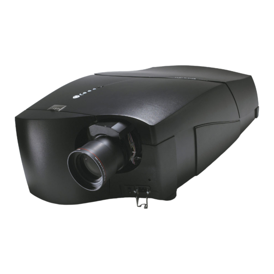
Article number Galaxy NW-7 R9040406 Galaxy NW-7 with options R9240406 R9040411 Galaxy NW-12 Galaxy NW-12 with options R9240411 About the Galaxy NW series The Galaxy NW series projector is a projector that can display 2D mono and 3D stereoscopic images in WUXGA resolution (1920x1200 active pixels). -
Page 12: Unpacking The Projector
3D stereo image of a hard-wired source; • a 2D mono image of a Remote Desktop Sharing source. Image 1-1 AUTION For more details about XDS Control Center, consult the related information on www.barco.com. Unpacking the projector Content Description Quantity Projector (weight ±... -
Page 13: Initial Inspection
This check should confirm that there are no broken knobs or connectors, that the cabinet and panel surfaces are free of dents and scratches, and that the operating panel is not damaged. The Barco Sales and Service office should be notified as soon as possible in case of irregularities. - Page 14 1. General R59770718 GALAXY NW SERIES 20/06/2013...
-
Page 15: Installation
2. Installation 2. INSTALLATION Overview • General installation guidelines • Projector position guidelines • Battery Installation in the RCU • Lens installation • Projector configuration • Positioning the projector • Connections • Controls overview General installation guidelines ARNING Prior to installing the projector, read the safety instructions in Safety manual R5976125 delivered with the projector. -
Page 16: Projector Position Guidelines
2. Installation Special Care for Laser Beams Special care should be used when DLP projectors are used in the same room as performant laser equipment. Direct or indirect hitting of a laser beam on to the lens can severely damage the Digital MicroMirror Devices™ in which case there is a loss of warranty Screen type ? There are two major categories of screens used for projection equipment. -
Page 17: Dimensions
2. Installation Image 2-1 Dimensions Dimensions below are given in mm and inch (1 inch = 25.4 mm) Air flow guidelines The hot air outlet at the rear side of the projector can reach high temperatures due to the high power lamp. Do not come near it while the projector is running with lamp switched on. -
Page 18: Cool Air Intake
2. Installation The cool air inlet at the bottom side of the projector may never be blocked. Always keep enough distance between projector’s bottom and support plate to allow a good air flow in. It is advised to also use an open projector support frame rather than a full support plate. -
Page 19: Battery Installation In The Rcu
2. Installation 360° Image 2-6 Projector tilt range AUTION Not respecting the projector tilt range causes lamp flicker or even premature lamp failure. Service area Make sure that sufficient free space (area free from obstacles - see the image below) should be available around the projector for maintenance and service activities. -
Page 20: Lens Installation
2. Installation RCU Top Image 2-8 Battery installation 4. Put the battery cover back on its place. Lens installation Overview • Lens range • Lens formulas • Shift capabilities • Lens installation 2.4.1 Lens range Overview table Lens Partnumber TLD+ (0.73:1) R9842041 R9840775 TLD+ (1.2:1) -
Page 21: Shift Capabilities
2. Installation The distances are measured starting from the back side of the flange of the projector lens. Image 2-9 2.4.3 Shift capabilities Description The maximum vertical and horizontal shift range depends on the lens. Shifting outside this range will not guarantee a full image i.e. some corners of the image will be clipped and will not be visible (will appear dark on the screen). -
Page 22: Lens Installation
2. Installation Vertical Shift in Nominal Position Vertical Shift : +100% Vertical Shift : -25% Projector Projector Projector Screen Screen Screen Image 2-11 Example of a vertical shift of +100% and -25% 2.4.4 Lens installation Necessary tools Hexagonal key 4 mm (hexagonal) - delivered with the projector Necessary parts •... -
Page 23: Projector Configuration
Projectors in ceiling configuration must have their second pump being connected mechanically and electrically! If no second pump is present in the projector, the corresponding kit must be installed first. Contact a Barco trained and certified technician. The different configurations Depending on the installation the projector can be mounted in different ways, the 4 different configurations are:... -
Page 24: Positioning The Projector
2. Installation Image 2-15 Projector configurations Positioning the projector On-Axis projection Projection where the projector is positioned so as to have the centre of the lens coinciding with the centre of the screen. Positioning the projector The position of the projector with reference to the screen may also be different depending on the installation. Basically the projector can be positioned in an On-Axis or Off-Axis configuration. -
Page 25: On-Axis Projector Installation
2. Installation C D = S H /2 + B -A Image 2-16 ON-Axis projector installation Side view Top view Back view Optical axis projection lens Projector Screen Floor R59770718 GALAXY NW SERIES 20/06/2013... -
Page 26: Off-Axis Projector Installation
2. Installation ref : front plate CD=B-A Image 2-17 OFF-Axis projector installation Side view Top view Back view Optical axis projection lens Projector Screen Floor A 100% Off-Axis position means that the position of the centre of the lens is shifted by half the screen height. R59770718 GALAXY NW SERIES 20/06/2013... -
Page 27: Connections
2. Installation Connections Overview • Power connection • The front panel • Connecting a DVI signal • Connecting an XDS Desktop computer • DVI output • Stereo connections • Active Infitec • Network connection • Network settings • Serial connection •... -
Page 28: The Front Panel
2. Installation OPEN LOCKED Image 2-19 Power plug spring system 2.7.2 The front panel View The front panel of the projector can be divided in 2 major parts : Signal Input/Output section System input/output section L1 L1 L2 L2 L3 L3 STEREO INPUT STEREO INPUT STEREO OUTPUT... -
Page 29: Connecting A Dvi Signal
2. Installation Layer 1 Layer 2 Layer 3 L1 L1 L2 L2 L3 L3 Layer 4 STEREO INPUT STEREO INPUT STEREO OUTPUT STEREO OUTPUT Layer 5 RS 232 C RS 232 C R.C. R.C. DESKTOP INPUT DESKTOP INPUT Image 2-21 Input layers Layer 3, 4 and 5 are fixed i.e. -
Page 30: Dvi Output
The projector can be connected to a LAN or can be connected to a desktop PC via a crossed cable (as indicated above). The desktop can be enabled/disabled, "Desktop", page 117 Using the desktop input makes only sense when using the Barco Desktop integration software. The Desktop integration software is covered in the Desktop integration User Guide. 2.7.5... -
Page 31: Stereo Connections
2. Installation AUTION If the selected input signal is a stereo signal, a black image is displayed at the DVI output. 2.7.6 Stereo connections What can be done ? The stereo sources sync signals have to be connected to the 4th layer of the front panel. The stereo input layer holds 6 mini DIN connectors and 2 BNC connectors. -
Page 32: Connecting Stereo Sources
2. Installation L1 L1 L2 L2 L3 L3 STEREO INPUT STEREO INPUT STEREO OUTPUT STEREO OUTPUT RS 232 C RS 232 C R.C. R.C. DESKTOP INPUT DESKTOP INPUT IR Emitter IR Emitter Image Generator Image Generator Active Glasses Image 2-27 Connecting stereo sources 2. -
Page 33: Active Infitec
2. Installation See the Display setup menu (for the stereo output and system settings) and the Image menu (for the stereo input settings) 2.7.7 Active Infitec The Active Infitec feature is optional: a software key is needed to activate it. How to connect when using active Infitec stereo ? 1. -
Page 34: Network Settings
2. Installation The linking of projectors is treated in the section “Setup of the linked projectors in a multichannel system” 2.7.9 Network settings AUTION Make sure that a DHCP server is available in the network and works fine. In normal conditions, the network detection takes few seconds. This means that the total time needed to go from power ON to Standby mode is only a few seconds. - Page 35 2. Installation Image 2-30 A dialog box will be displayed. Image 2-31 5. Push the cursor key ↑ or ↓ to highlight the desired parameter. 6. Use the cursor key ← or → , the numeric keys on the RCU, or the local keypad, to edit and change the values. 7.
-
Page 36: 2.7.10 Serial Connection
2. Installation A dialog box is shown. The different executed operations are shown with a checkbox. The last operation Restarting network takes a few seconds more. Image 2-32 2.7.10 Serial connection What is possible with the RS232 connection? Remote control: sending serial commands to control the projector (e.g. using a touchscreen device); Data communications: sending data to the projector or copying the data from the projector to a memory device (hard disc, etc.). -
Page 37: 2.7.11.2 Linked Dynacolor
2. Installation L1 L1 L2 L2 L3 L3 STEREO INPUT STEREO INPUT STEREO OUTPUT STEREO OUTPUT RS 232 C RS 232 C R.C. R.C. DESKTOP INPUT DESKTOP INPUT Network switch LAN1 LAN2 LAN3 LAN4 LAN5 LAN6 L1 L1 L2 L2 L3 L3 STEREO INPUT STEREO INPUT... -
Page 38: Linked Projectors For Stereo
2. Installation IR Emitter L1 L1 L2 L2 L3 L3 STEREO INPUT STEREO INPUT STEREO OUTPUT STEREO OUTPUT RS 232 C RS 232 C R.C. R.C. Active Glasses DESKTOP INPUT DESKTOP INPUT Image Generator IR Emitter CadWall Network switch LAN1 LAN2 LAN3 LAN4... -
Page 39: Controls Overview
2. Installation Controls overview MENU MENU BACK BACK ENTER ENTER PAUSE PAUSE AUTO IMAGE AUTO IMAGE DIGI DIGI ZOOM ZOOM PHASE PHASE IQ-PC IQ-PC TINT TINT Fire Wire Fire Wire COLOR COLOR VIDEO VIDEO S-VIDEO S-VIDEO BRIGHTN BRIGHTN PC PC CONTR CONTR LENS... -
Page 40: Lcd Display
2. Installation The LCD display The LCD display on the bottom of the front panel allows to inform the user on the status of the projector and other information like warnings etc. Galaxy NW-12 standby DESKTOP INPUT Image 2-38 LCD Display See the Appendix for a listing of the existing error messages. -
Page 41: Setup
3. Setup 3. SETUP Overview • Powering up the projector • Starting up the projector • Setting up the Remote Control Unit address • Setting up the projector address (only if necessary) • Setting up the orientation • Adjusting the lens •... -
Page 42: Starting Up The Projector
3. Setup In normal conditions, the network detection takes about 25 seconds. This means that the total time needed to go from power ON to Standby mode can take up to 85 seconds. This value can vary depending on the speed of the network connection. -
Page 43: Startup Sequence
3. Setup MENU BACK ENTER PAUSE LOGO DIGI ZOOM PHASE Image 3-5 Image 3-6 2. The projection lamp is started up. This may take up to 15 seconds. During this phase the LCD display and the keypad are lit (1). The progression is shown with the asterisk characters adding up (2). -
Page 44: Setting Up The Remote Control Unit Address
3. Setup Once the projector is operational, the information strings are rotating in the same way as in the standby mode (see Standby Status) Setting up the Remote Control Unit address Remote Control Unit What has to be done? To allow the communication between the RCU and the projector the RCU has to be programmed with the same address as the projector. -
Page 45: Setting Up The Projector Address (Only If Necessary)
3. Setup Setting up the projector address (only if necessary) What can be done ? The projector is shipped with projector address set to ”0” In some cases the projector address must be changed, for example if an unique RCU is used to control 2 or more projectors (inde- pendently). -
Page 46: Setting Up The Orientation
3. Setup Setting up the orientation What must be done ? Depending on the mechanical orientation of the projector, the projector’s internal settings have to be adapted. The projector is shipped (default) with a table/front orientation. How to set the orientation ? 1. - Page 47 3. Setup How to Zoom/focus or shift via the RCU (or keypad) 1. Press LENS ZOOM or LENS FOCUS or LENS SHIFT on the RCU BRI G HTN C O NTR L EN S L EN S Z OO M SH IFT L EN S F O CU S...
-
Page 48: Setup The Baud Rate For Serial Communication
3. Setup A text box appears on the screen, follow the instructions. Image 3-15 Image 3-16 The use of a sheet of paper held in front of the screen can be useful to determine the focus plane (position for best focus) Setup the baud rate for serial communication What can be done ? The RS232 IN port of the projector allows you to communicate with any other equipment disposing of an RS232 port (generally a... -
Page 49: Preferences
3. Setup Always select the highest rate unless otherwise specified. Preferences Overview • Language setting • Automatic startup • Change password 3.8.1 Language setting How to change the Language ? 1. Press MENU to activate the Tool bar 2. Press → to select the Installation item 3. -
Page 50: Change Password
3. Setup AUTION If the Automatic startup function is enabled one must be aware of the fact that it involves safety precautions Make sure that the projector (or the operators!) will not be affected by altered environmental conditions when restarting at power resume. Unless it is required, it is advised to leave this setting OFF. -
Page 51: Setup Of Linked Projectors In A Multichannel System
3. Setup Image 3-20 5. Press ENTER Image 3-21 Setup of Linked projectors in a Multichannel system What can be done ? The user interface of the projector allows to link up to 10 (slave) projectors to a single Master projector. The linking itself is done through an Ethernet connection (see Communications, "Connections", page 21). - Page 52 3. Setup In the Master projector, Stereo Mode may not be set to Auto. Either Always active or Infitec must be selected. The BNC cords between the projectors(coaxial link for stereo sync genlock) must be connected prior to check- ing the Stereo boxes in the Linked projectors dialog box of the Master projector. How to start up the linked projector menu ? 1.
- Page 53 3. Setup A dialog box is displayed Image 3-23 How to set a projector to Master ? 1. In the linked projector menu of the projector to be set as Master, Select the Master check box and press ENTER R59770718 GALAXY NW SERIES 20/06/2013...
- Page 54 3. Setup Image 3-24 How to set a projector as Slave ? 1. In the linked projector menu of the master projector, Select the Hostx check box and press ENTER The ip address edit box is enabled 2. Fill in the IP address or Host name of the projector to be declared as slave i.e. to be controlled by the Master For example IP address 150.158.193.110 3.
-
Page 55: Getting Started
4. Getting started 4. GETTING STARTED Overview • Starting up the projector • Selecting a source • Adjusting the image Starting up the projector How to start up the projector ? 1. Press the Standby button on the RCU or on the local keypad. See Setup for the detailed projector startup sequence. Selecting a source How to select a source ? 1. - Page 56 4. Getting started R59770718 GALAXY NW SERIES 20/06/2013...
-
Page 57: Advanced
5. Advanced 5. ADVANCED Overview • Using the menu • Using the Dialog boxes • Source selection • Image • Image files • Geometry • Lamps • General • Display setup • Installation • Service Using the menu Menu Layout A grey line (menu separator) indicates the transition between standard and advanced menu parameters. -
Page 58: Using The Dialog Boxes
5. Advanced How to exit the submenu ? 1. Press BACK to exit a submenu Press MENU to exit the menu When the menu has been exited for more than 1 minute, the advanced user password has to be re entered. Using the Dialog boxes How to use the dialog boxes ? Some parameters are modified by means of a dialog box, where selections can be made and/or values can be entered. -
Page 59: Source Selection
5. Advanced In some cases an alphanumeric value (file name, ...) has to be entered. Use ↑ or ↓ to scroll through the char- acter values once the input field is activated. Following characters can be browsed in this particular order: Decimal scroll list: 0123456789 Signed decimal scroll list: 0123456789- ASCII scrolllist:ABCDEFGHIJKLMNOPQRSTUVWXYZ0123456789+-*/&@#.;.abcdefghijklmnopqrstuvwxyz... -
Page 60: Image
5. Advanced Image 5-4 4. Press ENTER to confirm your choice A bullet indicates the selected DVI source which now appears on the screen. Adjustments on a DVI signal The digital nature of this signal eliminates the need of most adjustments Image Overview •... -
Page 61: Setting The Brightness
5. Advanced On the screen appears now a slider box Image 5-5 8. Use ←or → , the numeric keys on the remote, or the keypad to change the contrast 5.4.1.2 Setting the Brightness Brightness adjustment Adjusting the brightness will affect the dark areas of the image. Increase the brightness to “lighten” up the parts that are too dark. How to change the Brightness 1. -
Page 62: Phase (Rgb Signals Only)
5. Advanced On the screen appears now a slider box Image 5-7 8. Use ←or → , the numeric keys on the remote, or the keypad to change the Gamma 5.4.1.4 Phase (RGB signals only) Phase adjustment A bad phase adjustment will result in bad transitions and sometimes noise. (for example text will not be clear). How to adjust the Phase 1. -
Page 63: Anamorphic Aspect Ratios In (Non-Hdtv) Dvd Sources
5. Advanced 16:9 2.35:1 Image 5-10 Anamorphic aspect ratios in (non-HDTV) DVD sources In native HDTV DVD players the image is a real 16:9 format. 16:9 2.35:1 Image 5-11 Aspect ratios in native HDTV DVD sources 16:10 Image 5-12 Aspect ratio for WUXGA (1920x1200) What can be done ? The aspect ratio setting forces the projector to project an image using a defined aspect ratio : •... - Page 64 5. Advanced SOURCE PROJECTOR SETTING 16:10 16:9 native16:9 16:10 Image 5-13 We can conclude that the thumb rule for DVD projection is to always leave the projector in 4:3 format (except when dealing with anamorphic sources). The Auto function calculates an aspect ratio based on the information stored in the image files whereas Custom allows to set a personnel ratio.
- Page 65 5. Advanced Image 5-14 4. Use ↑ or ↓ to select Aspect ratio 5. Use → open the Aspect ratio menu 6. Use ↑ or ↓ to select the desired ratio 7. Press ENTER to confirm The aspect ratio settings are greyed out in case the Show native resolution or the Full screen representation setting is enabled.
-
Page 66: Color Temperature
5. Advanced 5.4.3 Color temperature What can be done ? The color temperature can be selected for the white point of the source. This is done according to the type of source: • Projector white • computer : 9300 K •... - Page 67 5. Advanced Δ G ΔΒ Δ R Black level Image 5-19 The objective of input balancing The objective in input balancing is to “set” the same black level and the same white level for the three colors of a particular input source.
-
Page 68: Performing Black Input Balance
5. Advanced An alternative to a full screen white/black pattern is a black-and-white checkerboard pattern where the white blocks will be used for white balance and the black blocks for black balance. Image 5-21 How to set Automatic Black level ? 1. - Page 69 5. Advanced Image 5-23 8. Press ENTER A dialog box is displayed 9. Adjust the red black level on a minimal value Image 5-24 10.Adjust the blue black level to a minimal value Note: this minimal value is not necessary , provided that the 2 other colors are not influencing too much the color to be adjusted, in fact the aim is to minimize the effect of the two other colors since there is a risk of reaching too soon the transition (bright spots) due to the contribution of these two other colors signals.
-
Page 70: Input Stereo Sync
5. Advanced Image 5-25 8. Press ENTER A dialog box is displayed 9. Adjust the red white level (gain) on a minimal value Image 5-26 10.Adjust the blue white level (gain) to a minimal value Note: this minimal value is not necessary , provided that the 2 other colors are not influencing too much the color to be adjusted, in fact the aim is to minimize the effect of the two other colors since there is a risk of reaching too soon the transition (bright spots) due to the contribution of these two other colors signals. -
Page 71: Stereo Swapped Fields
5. Advanced Field 1 (Left) Field 1 (Left) Field 2 (Right) Normal Left Stereo Sync Right Swapped fields Left Stereo Sync Right Image 5-27 Stereo Swapped fields It is also possible to select only field 1 or only field 2 This will, of course, remove the stereoscopic effect in the projected image. The swap field function acts at the input while the Invert Stereo (see Display setup) acts on the stereo emitter output. -
Page 72: Passive Infitec
5. Advanced 3. Press ↓ to Pull down the Image menu 4. Use ↑ or ↓ to select Input stereo sync 5. Press → to pull down the menu 6. Use ↓ or ↑ to select Only field 1 or Only field 2 Image 5-29 7. -
Page 73: Passive To Active Stereo
1. Connect each active stereo DVI input signal to a different input layer on the projector. 2. Check the presence of the input signals in the Source selection menu: select a different source (e.g. L1 PC). A Barco logo is visible in front of both corresponding DVI input connectors if the signals are present and detected. -
Page 74: Two Dvi Signals Detected
5. Advanced Source selection L1 PC L1 DVI L3 DVI-1 L3 DVI-2 Image 5-32 Two DVI signals detected 3. Browse to Image > Passive to Active Stereo... and click Enter. Image 5-33 4. Click the button next to Source 1. Image 5-34 5. - Page 75 5. Advanced 7. Store the settings by clicking Apply or store the settings and leave the menu by clicking OK. How to display an active stereo image starting from two passive stereo input signals? 1. Browse to Image > Passive to Active Stereo... and click Enter. Image 5-36 2.
-
Page 76: Image Files
L3 DVI-1 L3 DVI-2 Image 5-39 Two sources displayed simultaneously (bullet); one source available (Barco logo) 3. Browse to Installation > Scaled patterns and select Moving Hatch... Image 5-40 You should now see the Moving Hatch pattern and the Left image content at the same time. -
Page 77: Load File
5. Advanced When a new source corresponds to one of these files, a custom file is created. The custom file is automatically saved if a setting is altered (contrast, ...). The Save as... function allows to create and save a custom file. The active file can always be edited in order to fit exactly the source specifications. -
Page 78: Forced File Load
5. Advanced Image 5-43 6. Use ↑ or ↓ to select the desired file Tip: For more information (specifications) on the image files see the Appendix section 7. Press ENTER The file is loaded and the image is adapted. What to do if the image is not perfect ? If the displayed image is not correct after Auto Image or after selecting the best fitting file, go to the Edit menu, select the active file and change the settings. -
Page 79: Auto Image
5. Advanced Image 5-44 Note: Inputs that are not hardware compatible with this layer are greyed out. Note: if a file is already forced for that input it will be shown on the right. 9. Press ENTER The Load dialog box is displayed 10.Use ↑... -
Page 80: Edit
5. Advanced Image 5-45 7. Press ENTER AutoImage acts on the active window. The image in the window may move and change in aspect during the AutoImage process. Auto Image can also be launched via the RCU with the dedicated AutoImage key. 5.5.5 Edit What can be done with the Edit file menu ? -
Page 81: Which Items Can Be Adjusted
5. Advanced Image 5-47 6. Use ←or →, the numeric keys on the remote, or the keypad to edit and change the values, confirm with ENTER Note: greyed out fields can not be updated (total pixels) Which items can be adjusted ? The following items can be adjusted : •... -
Page 82: Save As (Create A Custom File)
5. Advanced Advanced settings for Digital Data sources (DVI and HDSDI) The advanced button enables the advanced settings for a DVI source. Image 5-49 UsePictureBox can be disabled (0) or enabled (1). By default, it is disabled which means that only few timings can be changed. In case of a DVI source this is not a problem. -
Page 83: Rename File
5. Advanced Image 5-52 5.5.7 Rename file How to rename a file ? 1. Press MENU to activate the Tool bar 2. Press → to select the Image files item 3. Press ↓ to Pull down the Image files menu 4. -
Page 84: Delete
5. Advanced Image 5-55 5. Press ENTER A dialog box is displayed Image 5-56 6. Use ↑ or ↓ to select the file to be copied 7. Press ENTER The file name is copied in the edit field 8. Use the keys on the remote to change the name of the destination file 5.5.9 Delete How to delete a file ? -
Page 85: Geometry
5. Advanced A dialog box is displayed Image 5-58 6. Use ↑ or ↓ to select the desired file 7. Press ENTER The selected file is deleted and is removed from the list Geometry Overview • Introduction • Geometry files •... -
Page 86: Accessing The Geometry Menu
5. Advanced Standard file directory, also the type of file : Custom or Standard Dist_file1 file name file extension Available Geometry operations • Load : loads an existing standard or custom geometry file • Edit : allows to edit a custom geometry file •... -
Page 87: Geometry Levels
5. Advanced Modes and Levels The geometry adjustment is divided in 6 groups or modes : • • • • • 17x17 • 33x33 These modes represent 21 levels, each level represents a group of points (or zones). Each level will interact with other levels, adjusting a point on a certain level will affect points in the levels underneath. -
Page 88: Load
5. Advanced Level 1 Level 2 Level 3 Level 4 Level 5 Level 6 Level 7 Level 8 Level 9 Level 10 Level 11 Level 12 Level 13 17x17 Level 14 Level 15 Level 16 Level 17 Level 18 33x33 Level 19 Level 20 Level 21... -
Page 89: Edit
5. Advanced 5. Press ENTER A dialog box is displayed Image 5-64 6. Use the cursor key ↑ and ↓ to select the desired geometry file 7. Press ENTER Tip: When starting a new geometry setup it is advised to select the “No_Distortion” file. The file is loaded and the geometry settings are adapted. -
Page 90: Geometry Edit Wizard
5. Advanced Image 5-65 5.6.6.2 Geometry Edit wizard The geometry wizard When entering the Edit mode, the Edit dialog box is displayed. When selecting a point in a certain adjustment, a yellow box shows the selection and a blue dotted box is placed around the selected grid point, indicating the interaction zone. Image 5-66 R59770718 GALAXY NW SERIES 20/06/2013... - Page 91 5. Advanced Image 5-67 Note that the dialog box is transparent so as to allow the preview of the adjustment over the whole screen during the adjustment (the image to be adjusted is not hidden by the dialog box) Description of the Edit dialog box An intuitive user interface is used to perform all the geometry corrections.
-
Page 92: Geometry Edit Modes
5. Advanced Field Description Notes /adjustment Colom column corresponding to the selected point in a 2x2 adjustment column will be between 0 and 32 (steps of 32) row corresponding to the selected point in a 2x2 adjustment row will be between 0 and 32 (steps of 32) PixelX this slider box adjusts the new position of the point along... - Page 93 5. Advanced Image 5-70 Image 5-71 Image 5-72 R59770718 GALAXY NW SERIES 20/06/2013...
-
Page 94: Editing A Geometry File
5. Advanced How to select an Edit Mode ? 1. When the Edit dialog box is displayed, the Select mode is selected by default. 2. To go to the next mode (go to the right) press ENTER. 3. To return to a previous mode (go to the left) use BACK 5.6.6.4 Editing a geometry file Introduction... - Page 95 5. Advanced 11 12 13 14 15 16 17 18 19 20 21 22 Image 5-74 A 5x5 mode adjustment gives the following new points to be adjusted. Note that in this mode 3 levels are involved, level 4, 5 and level 6 (previous adjusted points are left out).
- Page 96 5. Advanced A dialog box is displayed. The Select mode is enabled and the top/left (row = 0 ; colom = 0) corner is selected Image 5-76 Image 5-77 How to select another point ? 1. Press → to select the next adjustment point R59770718 GALAXY NW SERIES 20/06/2013...
- Page 97 5. Advanced The column is adapted to 32 Image 5-78 Image 5-79 2. Press ↓ to select the next adjustment point The row is adapted to 32 R59770718 GALAXY NW SERIES 20/06/2013...
- Page 98 5. Advanced Image 5-80 Image 5-81 3. Press ← to select the next adjustment point R59770718 GALAXY NW SERIES 20/06/2013...
- Page 99 5. Advanced Image 5-82 Image 5-83 How to adjust using the Adjust mode ? Adjusting point (row =0 ; column =0) by 100 (pixels) along the x axis in the 2x2 mode 1. Press ENTER to go to the Adjust Mode The Adjust mode is selected R59770718 GALAXY NW SERIES 20/06/2013...
- Page 100 5. Advanced Image 5-84 2. Use ← and → to adapt the value of PixelsX Tip: Use ↑ and ↓ to adapt the value of PixelsY The image is distorted along the X axis. Notice the unaffected regions. Image 5-85 The adjustment is done in small steps.
-
Page 101: Axis Link
5. Advanced The Edit mode is selected Image 5-86 2. Use ↑ and ↓ to select the PixelsX edit box The PixelsX edit box is focused 3. Press ENTER The PixelsX edit box is put in edit mode Image 5-87 4. - Page 102 5. Advanced Following example will show a basic 2x2 adjustment with AxisLink set On and Off. Start with a non distorted image, assume the left top corner is selected. Image 5-88 Shift the left top corner +300 pixels to the left. Image 5-89 R59770718 GALAXY NW SERIES 20/06/2013...
- Page 103 5. Advanced Shift the left corner +300 pixels downwards. AxisLink = ON The coordinate system used for the adjustment will coincide with the edges of the distorted image, this will result in a quick adjustment when dealing with complex setups. AxisLink = The coordinate system used for the adjustment is absolute.
-
Page 104: Shift Adjustment
5. Advanced Image 5-91 3. Use ↑ and ↓ to select the AxisLink radio buttons Image 5-92 4. Use ← and → to select the ON or OFF radio buttons 5. Press ENTER to enable/disable the selected radio button 6. Press BACK to return to the Geometry Edit menu. 5.6.6.6 Shift Adjustment What can be done with the Shift adjustment ? - Page 105 5. Advanced The Edit mode is selected Image 5-93 5. Use ↑ and ↓ to select the PixelsX edit box The PixelsX edit box is focused Image 5-94 6. Press ENTER R59770718 GALAXY NW SERIES 20/06/2013...
-
Page 106: Transport Delay
5. Advanced The PixelsX edit box is put in edit mode Image 5-95 7. Use ← and → to select the digit and use ↑ and ↓ to increment/decrement the digit Tip: One can also use the numeric digits to fill in the desired value ? The image is shifted along the X axis. -
Page 107: Transport Delay
5. Advanced signal coming frame B frame C frame D from PMP (1st step) signal processing frame B frame C frame D in PMP (2nd step) z = transport delay or TDR Image 5-97 Transport delay During this delay all image information is stored in a memory block on the PMP. A Transport Delay set to the maximum value of 1023, corresponds with a delay of 16 ms. -
Page 108: Sharpness
5. Advanced Image 5-99 The Transport Delay dialog box will be displayed. Image 5-100 3. Push the cursor key ↑ or ↓ to select the radio buttons 4. Press ENTER to check the desired radio button 5. Press BACK to return to the Geometry Edit menu. How to adjust the Transport Delay manually? 1. -
Page 109: Geometry Reset
5. Advanced How to adjust the geometry Sharpness ? 1. Start up the Geometry Edit menu 2. Push the cursor key ↑ or ↓ to highlight Sharpness... and press ENTER to select. Image 5-102 The Sharpness dialog box will be displayed. Image 5-103 3. -
Page 110: Restore To A Level
5. Advanced Image 5-104 All the levels are reset. If these levels contained geometry corrections, this will be noticed in the image by a jump. 5. Press BACK to return to the Geometry Edit menu. 5.6.6.9.2 Restore to a level What can be done ? Restore to a level means that all the higher level geometry corrections are reset (all geometry correction values are set to 0). -
Page 111: Geometry Restore Example : Restoring To A 9X9 Level
5. Advanced Image 5-105 Geometry Restore example : restoring to a 9x9 level How to restore to a level ? 1. Start the Geometry Edit menu 2. Push ↓ or ↑ to select Reset 3. Push the → key to pull down the menu. 4. -
Page 112: Rename A Geometry File
5. Advanced Image 5-106 The higher levels are reset. If these levels contained geometry corrections, this will be noticed in the image by a more or less accentuated jump. 5. Press BACK to return to the Geometry Edit menu. 5.6.7 Rename a Geometry File How to rename a geometry file ? 1. -
Page 113: Copy A Geometry File
5. Advanced A dialog box is displayed Image 5-108 4. Use the cursor key ← or → to go to the next or previous characters and use ↓ or ↑ to browse through the characters 5. Press ENTER The file is renamed. 6. -
Page 114: Delete A Geometry File
5. Advanced Image 5-110 4. Use the cursor key ↑ and ↓ to select the desired geometry file 5. Press ENTER to select. 6. Use the cursor key ← or → , the numeric keys on the RCU, or the local keypad, to edit and change the values, confirm with ENTER. -
Page 115: Lamps
5. Advanced 4. Use the cursor key ↑ and ↓ to select the desired geometry file and press ENTER to select. A message will be displayed. Image 5-113 5. Press ENTER to confirm. The selected file is deleted and removed from the list. 6. -
Page 116: Lamp Runtime Warning
5. Advanced Image 5-114 5. Press ENTER A text box is displayed Image 5-115 5.7.2 Lamp runtime warning What can be done ? When the lamp has reached a predetermined runtime , a warning message will be displayed on the screen. The lamp runtime warning can be set in a range from 30 to 200 hours. -
Page 117: Lamp Power Mode
5. Advanced 5. Press ENTER A dialog box is displayed Image 5-117 6. Use ←or →, the numeric keys on the remote, or the keypad to change the runtime warning setting. 5.7.3 Lamp Power Mode What can be done? The Lamp can be set to the normal or economic mode. Following Mode Settings are available: NORMAL Normal Light Output... -
Page 118: Constant Light Output Mode
5. Advanced 5.7.4.1 Constant Light Output Mode What can be done? Constant Light Output allows to force a constant light output (set in the CLO Target ... menu) of the projector over a certain period. This will eliminate uncontrolled light output drop caused by natural aging of the lamp. The light output is checked every 5 minutes, if the target is not met, the lamp power is adjusted. -
Page 119: Clo Target
5. Advanced 5. Press → to pull down the menu 6. Use ↑ or ↓ to select Mode 7. Press → to pull down the menu 8. Use ↑ or ↓ to select ON or OFF Image 5-121 9. Press ENTER A bullet shows the active setting 5.7.4.2 CLO Target... -
Page 120: Linked Clo
5. Advanced A dialog box is displayed Image 5-123 10.Use ←or →, the numeric keys on the remote, or the keypad to change the target value. 5.7.4.3 Linked CLO Introduction Projectors in a multichannel setup use the same kind of lamp. These lamps may slightly differ in their output and will in certain cases have different runtimes, this will result in a difference in light output between the projectors. -
Page 121: Pause
5. Advanced Image 5-124 5. Press ENTER On the screen appears a text box. 6. Press MENU or BACK to exit or to go back to the previous menu 5.8.2 Pause Pause The Pause function allows to stop the image display, the projector remaining with full power for immediate restart. The image display is interrupted and the projected background is black. -
Page 122: Standby Timer
5. Advanced Image 5-126 5. Press ENTER to activate the Freeze function The image can also be frozen using the FREEZE key on the RCU 5.8.4 Standby Timer What can be done ? If there is no (sync) signal at any of the input connectors, and the standby timer is enabled, the projector will shut down after a pre determined time. -
Page 123: Desktop
7. Press ENTER The desktop is displayed if the desktop PC is connected (see connections) Using Desktop makes only sense when using the Barco Desktop integration software. The Desktop integra- tion software is covered in the Desktop integration User Guide. -
Page 124: Stereo Display Settings
5. Advanced 3. Press ↓ to Pull down the Display setup menu 4. Use ↑ or ↓ to select Textbox 5. Press → to pull down the menu 6. Use ↓ or ↑ to enable (ON) or disable (OFF) the textbox Image 5-130 7. -
Page 125: Mono Source : Full Screen Synchronous Representation Off And Stereo Mode = Always Active
5. Advanced FULL SCREEN SYNCHRONOUS MODE = off SOURCE = mono STEREO MODE = always active @120Hz ASYNC f(Hz) In this case: All the mono sources (for all the vertical refresh rates) are displayed “ASYNChroneously” at 120 Hz. Image 5-131 Mono source : Full screen synchronous representation OFF and Stereo Mode = Always Active SOURCE = mono FULL SCREEN SYNCHRONOUS MODE = off... -
Page 126: Stereo Mode
5. Advanced • Full screen synchronous representation Following illustrations give an overview on how a stereo source will be displayed in function of its vertical refresh rate and for the different settings mentioned above. SOURCE = stereo FULL SCREEN SYNCHRONOUS MODE = on @120Hz @2Xf source @120Hz... -
Page 127: Full Screen Synchronous Representation Settings
5. Advanced 4. Use ↑ or ↓ to select Stereo Mode 5. Press → to pull down the menu 6. Use ↓ or ↑ to select Auto, Always or Infitec Image 5-137 7. Press ENTER A white bullet shows the active setting 5.9.3 Full screen synchronous representation settings Overview... - Page 128 5. Advanced How to enable/disable the full-screen synchronous representation in (Galaxy) NW-12/NH-12, NW-12, iD LH12, iCon NH-12 ? 1. Press MENU to activate the Tool bar 2. Press → to select the Display setup item 3. Press ↓ to Pull down the Display setup menu 4.
-
Page 129: Asynchronous Frequency
5. Advanced A bullet shows the active setting 5.9.3.2 Asynchronous frequency What can be done ? The frequency can be set to either low or high. In the synchronous mode, the display will be refreshed at the same vertical frequency as the displayed source. -
Page 130: Status Bar Position
5. Advanced 2. Press → to select the Display setup item 3. Press ↓ to Pull down the Display setup menu 4. Use ↑ or ↓ to select Menu bar position menu 5. Press ENTER Image 5-141 6. Use ↑ or ↓ to position the Menu bar 5.9.5 Status bar position What can be done ? -
Page 131: Slider Box Position
5. Advanced 5.9.6 Slider box position What can be done ? The slider box function allows to display or hide the different boxes used for instance for picture settings (contrast, ...). How to reposition the slider box? 1. Press MENU to activate the Tool bar 2. -
Page 132: The Cie Chromaticity Diagram
5. Advanced Image 5-144 The CIE chromaticity diagram A projector can only reproduce a certain color gamut within this diagram. This color gamut is defined by the triangle formed by the x, y coordinates of Red, Green, and Blue. These parameters are used by the DynaColor™ adjustment in the projector. Image 5-145 The projector color gamut is defined by the triangle formed by the x, y coordinates of Red Green and Blue Due to tolerances on lamps and other optical components the x, y values of this color gamut of each projector is different. -
Page 133: Common Color Gamut
5. Advanced Image 5-147 Common Color Gamut The Common Color Gamut In a basic setup with 2 projectors, the perimeter of the Common Color Gamut is described by the 6 points of intersection of the 2 separate color gamuts. Image 5-148 The Common Color Gamut Red projector 1 Red projector 2... - Page 134 5. Advanced Blue Projector 2 W1 White Projector 1 W2 White Projector 2 Red Common Color Gamut Green Common Color Gamut Blue Common Color Gamut Cyan Common Color Gamut Magenta Common Color Gamut Yellow Common Color Gamut Wc White Common Color Gamut The following parameters can be adjusted within DynaColor™: •...
-
Page 135: Choosing Dynacolor Sets
5. Advanced Factory Preset Sets the measured parameters back to the factory preset for the current set Calibration This starts the calibration procedure for the measured points of the current set (Changing these settings may seriously affect the performance of the projector). Default Desired This will reset the desired parameters to no color change values (measured values). -
Page 136: Enabling Dynacolor
5. Advanced Overview of Dynacolor sets Depending on the projector settings, different Dynacolor sets are enabled and/or available: • Monoscopic mode: two Dynacolor sets (Set 1 and Set 2) can be selected and adjusted; • Active stereo mode: two Dynacolor sets (Set 1 and Set 2) can be selected and adjusted; •... -
Page 137: Linking Dynacolor
5.9.7.4 Linking DynaColor AUTION Only to be done by Barco trained and qualified engineers. What can be done? To calculate the common color triangle of multiple projectors and apply it to the selected DynaColor™ set in each of the projectors, we can use Linked DynaColor™... -
Page 138: Matching Infitec A And Infitec B
5. Advanced Image 5-152 The CPU of the Master now reads the native (i.e. measured) color triangle of each Host, calculates a common triangle and writes the coordinates of the common triangle as desired values in the selected DynaColor™ set and of itself. Make sure to link (i.e. -
Page 139: Changing Color Reproduction
5. Advanced Image 5-153 7. Press ENTER Common color coordinates are calculated and filled in the desired values. 5.9.7.6 Changing color reproduction Concept Dynacolor allows setting a desired color reproduction - within the limits of the device - by digitally changing the primary and secondary color coordinates. -
Page 140: Moving The Desired White Point
Moving the desired white point AUTION Color fine tuning may only be done by Barco trained and qualified engineers. Fine tuning the color of the projected image 1. In the OSD, navigate to the active Dynacolor set: Display setup > Dynacolor > or Adjust Set 1...> Adjust Set 2... or Adjust Infitec A... - Page 141 5. Advanced Image 5-156 3. In the Dynacolor Set dialog, enter a well-considered new value for X and/or Y of White. Image 5-157 Note: Make sure that the new [X, Y]-position is within the desired color triangle. R59770718 GALAXY NW SERIES 20/06/2013...
-
Page 142: Black Color Matching
4. The same procedure applies for the other sets. 5.9.7.7 Black Color Matching AUTION May only to be done by Barco trained and qualified engineers! Never change the values if not needed. Altered color values will not guarantee optimal image reproduction. Overview •... -
Page 143: Black Color Adjustment For Set 1
5. Advanced 5.9.7.7.2 Black Color adjustment for Set 1 How to adjust black color for Set 1 ? 1. Press MENU to activate the Tool bar 2. Press → to select the Display setup item 3. Press ↓ to Pull down the Display setup menu 4. -
Page 144: Stereo System Setup
5. Advanced 10.Use ← or → or ↑ or ↓, the numeric keys on the remote, or the keypad to change the settings. 5.9.8 Stereo System Setup Overview • Dark Time • Invert stereo • Stereo Phase The stereo system settings allow to match the stereo peripherals (glasses, emitters,...) 5.9.8.1 Dark Time For Active Infitec+ , Dark Time can also be adjusted for optimal stereo separation... -
Page 145: Shutters Closing Too Late And/Or Opening Too Early Cause Cross-Talk
5. Advanced Opening Too Early and/or Closing Too Late = Cross Talk DLP Mirrors Active Blanking Time Left Shutter Open Closed Right Shutter Open Closed Image 5-162 Shutters closing too late and/or opening too early cause Cross-Talk Closing these shutters too quickly and/or opening too slowly will cause Color Artifacts. Opening Too Late and/or Closing Too Early = Color Artifacts DLP Mirrors... -
Page 146: Invert Stereo
5. Advanced 2. Press → to select the Display setup item 3. Press ↓ to Pull down the Display setup menu 4. Use ↑ or ↓ to select Stereo 5. Press → to pull down the menu 6. Use ↓ or ↑ to select Dark Time... Image 5-164 7. -
Page 147: Inverted Stereo
5. Advanced Left Left Right Normal Left Stereo Sync Right Inverted Left Stereo Sync Right Image 5-166 Inverted stereo The Invert stereo function acts at the output (stereo emitters) while the Swapped fields (see Image) acts on the input stage. How to invert stereo ? 1. -
Page 148: Stereo Phase
5. Advanced A white bullet shows the active setting 5.9.8.3 Stereo Phase For Active Infitec+ , Phase can also be adjusted for optimal stereo separation What can be done? With Stereo Phase it is possible to apply an adjustable time delay on the stereo emitter signal. Image Frame Left Frame Right... -
Page 149: Soft Edge
5. Advanced Image 5-169 7. Press ENTER A slider box is displayed Image 5-170 8. Use ←or →, the numeric keys on the remote, or the keypad to change the Stereo Phase setting. 5.9.9 Soft edge Overview • Introduction • Soft edge adjustments •... -
Page 150: Soft Edge Adjustments
5. Advanced Adjustable overlapping area Light output per image 100% image 1 image 2 Total composite light output 100% image 1 image 2 Image 5-172 Soft Edge Basic Principle Internal versus external (Alpha planes) The projector offers 2 methods to achieve soft edging : Internal soft edges : the contour and shape can be adjusted in the projector using the soft edge edit wizard External Alpha planes : An external file is sent to the projector and is memorized. -
Page 151: Soft Edge : Adjustment Points
5. Advanced Image 5-173 Soft edge : adjustment points Image 5-174 Soft edge : points numbering, Top and bottom side edges R59770718 GALAXY NW SERIES 20/06/2013... -
Page 152: Soft Edge : Points Numbering, Left And Right Side Edges
5. Advanced Image 5-175 Soft edge : points numbering, left and right side edges Levels The soft edge adjustment is divided in 6 levels. Each level represents a group of points and interacts with other levels, adjusting a point on a certain level will affect points in the levels underneath. -
Page 153: Accessing The Soft Edge Menu
5. Advanced Level Hierarchy The fact that the adjustment affects other points means that a certain hierarchy must be respected when adjusting the geometry. The hierarchy or levels are indicated in the following image Level 1 Level 2 Level 3 Level 4 Level 5 Level 6... -
Page 154: The Soft Edge Edit Wizard
5. Advanced 5.9.9.4.1 The soft edge edit wizard The geometry wizard When entering the Edit mode, the Edit dialog box is displayed. Description of the Edit dialog box An intuitive user interface is used to perform all the Soft edge adjustments. Image 5-179 Field Description... - Page 155 5. Advanced Image 5-180 Image 5-181 Image 5-182 Image 5-183 R59770718 GALAXY NW SERIES 20/06/2013...
-
Page 156: Creating/Editing A Soft Edge
5. Advanced How to select an Edit Mode ? 1. When the Edit dialog box is displayed, the Select mode is selected by default. 2. To go to the next mode press ENTER. 3. To return to a previous mode use BACK 5.9.9.4.3 Creating/editing a soft edge Description... - Page 157 5. Advanced The item is focused Image 5-185 2. Press ENTER The internal soft edge is selected Image 5-186 How to enable the soft edges ? 1. Push ↓or ↑ to select the desired Edges check box R59770718 GALAXY NW SERIES 20/06/2013...
- Page 158 5. Advanced The item is focused Image 5-187 2. Press ENTER The selected check boxes are checked Image 5-188 3. Do the same for the other desired edges The default soft edge is applied on the selected edges How to select the source (background) ? 1.
- Page 159 5. Advanced The item is focused Image 5-189 2. Press ENTER The selected check box is checked and a full white image is displayed with the soft edges on the 4 sides Image 5-190 R59770718 GALAXY NW SERIES 20/06/2013...
- Page 160 5. Advanced Image 5-191 How to enable the adjustment guide ? 1. Push ↓or ↑ to select the check box ON to enable the adjustment guide The item is focused Image 5-192 2. Press ENTER R59770718 GALAXY NW SERIES 20/06/2013...
- Page 161 5. Advanced The selected check box is checked and the guide is displayed (vertical and horizontal grey scale bars) Image 5-193 Image 5-194 How to set the hierarchy level ? 1. Push ↓or ↑ to select the hierarchy level slider box R59770718 GALAXY NW SERIES 20/06/2013...
- Page 162 5. Advanced The item is focused Image 5-195 2. Use the ← and → to select the level (from 1 to 6) How to adjust the soft edge ? 1. Press Adjust A Edit dialog box is displayed and the left side soft edge zone is selected. The default level is the level 1. Image 5-196 2.
-
Page 163: Alpha Planes
5. Advanced The selected point is displaced to the new position (x=100 ; Y=0). Image 5-197 8. Press BACK to exit A dialog box is displayed. Press ENTER to confirm All the points of the higher levels (level 2, ...) are altered by this adjustment. The points that belong to the same level (level 1) remain in the same position (anchors). -
Page 164: Black Level
5. Advanced 6. Push the cursor key ← or → to highlight Edit... Image 5-198 7. Press ENTER A dialog box will be displayed. 8. Use the arrows to select the Alpha planes check box and press ENTER Image 5-199 Note: It will take a certain time for the alpha plane to be applied 5.9.9.5 Black level... -
Page 165: Internal Black Level
5. Advanced Internal black level versus Beta Planes In the same way as for the soft edge adjustment (Internal vs Alpha planes) this black level adjustment can be fixed internally by using a dialog box or externally by uploading a user defined Beta plane. This beta plane will contain the values for the brightness offset to be applied to the image. -
Page 166: Beta Planes
5. Advanced How to adjust the internal black level ? 1. Press the MENU key to activate the Tool bar. 2. Push the cursor key ← or → to highlight Display setup 3. Push the ↓ key to pull down the menu. 4. -
Page 167: Blanking
5. Advanced How to activate a beta plane ? 1. Press the MENU key to activate the Tool bar. 2. Push the cursor key ← or → to highlight Display setup 3. Push the ↓ key to pull down the menu. 4. -
Page 168: 5.9.10 Autoimage Setup
5. Advanced Image 5-205 7. Press ENTER The soft edge dialog box will be displayed. 8. Uncheck all the edges 9. Adjust the soft edge as desired (same procedure as above) 10.Press BACK to return to the Display setup menu. 5.9.10 AutoImage Setup What can be done ? AutoImage allows to detect automatically the characteristics of the source (total pixels per line,...) and uses this information to adapt... -
Page 169: True Motion Reproduction (Tmr)
5. Advanced Image 5-206 5. Press ENTER A dialog box is displayed. Image 5-207 6. Use the arrow keys to select the desired check box and press ENTER to activate or deactivate the item. 5.9.11 True motion reproduction (TMR) What can be done? If the image shows fast moving images like airplanes, smearing can be visible. -
Page 170: 5.10 Installation
(left/right image processing). AUTION This setting is only for Barco certified service personnel. Changing this setting may not guarantee optimal image quality. An optional Infitec™ wheel assembly is needed to be installed first (by default not present) in the Galaxy NW-7 and then adjusted through OSD. -
Page 171: 5.10.2 Internal Patterns
5. Advanced Image 5-209 5. Press ENTER A dialog box is displayed Use ←or →, ↓ or ↑ the numeric keys on the remote, or the keypad to edit and change the values. Image 5-210 5.10.2 Internal Patterns Overview The projector is equipped with different internal patterns which can be used for adjustment purposes. Geometry adjustments can not be used on these internal patterns. -
Page 172: Color Bars
5. Advanced Image 5-213 Image 5-214 Color bars Checkerboard Image 5-216 Image 5-215 H pattern HGBWS Image 5-217 Convergence Level -1 Level +1 Level -16 Level +16 Min Level: 0 Max Level: 255 Gray Levels Red Levels Green Levels Blue Levels Image 5-218 Purity How to select an internal pattern ? -
Page 173: 5.10.3 Scaled Patterns
5. Advanced 3. Press ↓ to Pull down the menu 4. Use ↑ or ↓ to select Internal Patterns Image 5-219 5. Press → to Pull down the menu 6. Use ↑ or ↓ to select the desired internal pattern 7. -
Page 174: Scaled Patterns : Stereo Pattern
5. Advanced Image 5-222 Scaled patterns : Stereo pattern How to select an internal pattern ? 1. Press MENU to activate the Tool bar 2. Press → to select the Installation menu 3. Press ↓ to Pull down the menu 4. -
Page 175: 5.10.4 Formatter Patterns
5. Advanced 5.10.4 Formatter patterns Overview Image 5-224 Image 5-225 Horizontal ramp Vertical ramp How to select a formatter pattern ? 1. Press MENU to activate the Tool bar 2. Press → to select the Installation menu 3. Press ↓ to Pull down the menu 4. -
Page 176: 5.10.5 Stereo Sync Out
5. Advanced 5.10.5 Stereo sync out What can be done ? The sync signal present on the stereo output BNC connectors can be disabled. In a multichannel stereo linked system multiple projectors can be linked via the BNC stereo output connectors to allow them to be synchronized. The Stereo sync out function can be necessary if one wants to prevent the next projector(s) in the loop to be synchronized (for maintenance purposes). - Page 177 5. Advanced How to launch the convergence dialogbox? 1. Press MENU to activate the Tool bar 2. Press → to select the Installation menu 3. Press ↓ to Pull down the menu 4. Use ↑ or ↓ to select Convergence Image 5-228 5.
-
Page 178: 5.11 Service
5.11.2 Option key AUTION This menu is only intended for authorized personnel! Only to be used to activate your option key purchased at Barco! How to activate a new purchased option ? 1. Press MENU to activate the Tool bar 2. -
Page 179: 5.11.4 Operation Options
5. Advanced 5.11.4 Operation options Overview • AutoImage • Warning messages 5.11.4.1 AutoImage What can be done ? AutoImage can be disabled. In case of a new (unknow) source, no automatic file selection will be done. Instead, a more or less suited file will be selected, resulting in a misaligned image. - Page 180 5. Advanced How to enable/disable Warning Messages? 1. Press MENU to activate the Tool bar 2. Press → to select the Service item 3. Press ↓ to Pull down the Service menu 4. Use ↑ or ↓ to select Operation options 5.
-
Page 181: Maintenance
6. Maintenance 6. MAINTENANCE About this chapter This chapter contains information about the timing of maintenance tasks and it includes details about the maintenance procedures that can be performed by the operator or by qualified technical service personnel. Contact a Qualified Product Specialist or Qualified Product Expert for the maintenance tasks that need to be performed by them. -
Page 182: Visual Checks
If they can not solve the issue or if they are not sure about the way to proceed, they can escalate the issue to a Product Specialist, a Product Expert or to Barco Helpdesk http://www.barco.com/en/Support. Visual check of the projector housing 1. -
Page 183: Cleaning Housing And Mechanical Structure
6. Maintenance Remove any foreign elements or substances. 3. Check on moisture or liquid. Keep the projection lens dry at all times. Visual check of the projected image 1. Display each of the listed test patterns in turn and evaluate the projected image for each of them. Full white Full black Full red... -
Page 184: Checking The Cooling Liquid Level
6. Maintenance AUTION Do not apply any liquid to the lens, nor the cleaning cloth. Do not use fabric softener when washing the cleaning cloth or softener sheets when drying it. Do not wipe back and forward across the lens surface as this tends to grind dirt into the coating. Checking the cooling liquid level Cooling liquid level The liquid level of the cooling system must be checked before first use and then on a regular basis. -
Page 185: Lamp Description
6. Maintenance 6.6.1 Lamp description Description The lamp is a 2 kW Xenon lamp. A lamp that has reached its end of life, can be refurbished a number of times. This implicates that the housing is partly reused a few times and the bulb is replaced only. The content of the flash memory is also updated during refurbishment. -
Page 186: Removing The Fan Outlet
6. Maintenance Image 6-2 Rear cover: fixing screw 2. Lift the back side of the rear cover and pull it backward to remove it Image 6-3 Image 6-4 Image 6-5 Tilt the back side of the rear cover Pull the rear cover backward Rear cover removed 6.6.3 Removing the fan outlet... -
Page 187: Removing The Lamp
6. Maintenance Image 6-7 Fan outlet: lift to remove 6.6.4 Removing the lamp Necessary tools Slotted screwdriver 4 mm or 6 mm How to remove the lamp? Make sure the projector has finished its cooling down cycle and wait for 15 more minutes before starting this procedure. 1. -
Page 188: Installing The Lamp
6. Maintenance 5. Lift the lamp to remove it Tip: Use the handle at the top side of the lamp. Image 6-10 Image 6-11 Lamp: removing Lamp: removed 6.6.5 Installing the lamp Necessary tools Slotted screwdriver 4 mm or 6 mm How to install the lamp? 1. -
Page 189: Installing The Fan Outlet
6. Maintenance 3. Slide the lamp to the right side of the projector (= towards the connector) Image 6-15 Lamp: installation 4. Push the lamp to plug in the connectors cathode anode lamp info connector (bottom side of the lamp) Caution: If the lamp doesn’t slide in smoothly, gently wiggle it until it does. -
Page 190: Installing The Rear Cover
6. Maintenance Image 6-17 Fan outlet: installing 2. Fix the fan outlet to the projector using the fixing screw Image 6-18 Fan outlet: fixing screw 3. Install the rear cover (see concerning chapter) 6.6.7 Installing the rear cover Necessary tools Philip screwdriver Ph2 How to install the rear cover? 1. -
Page 191: Installing The Rear Cover: Step 2
6. Maintenance Image 6-20 Image 6-21 Image 6-22 Installing the rear cover: step 2 Installing the rear cover: step 3 Installing the rear cover: step 4 3. Fix the rear cover using the fixing screw Image 6-23 Installing the rear cover: step 5 R59770718 GALAXY NW SERIES 20/06/2013... - Page 192 6. Maintenance R59770718 GALAXY NW SERIES 20/06/2013...
-
Page 193: Trouble Shooting
H: hardware error If ever you have to contact Barco’s Helpdesk concerning an error code, make sure to mention the prefix and both digits, since this data is most useful for Barco engineers to determine which actions have to be taken. - Page 194 7. Trouble shooting Description Location Prefix Code Message fan side LPS LPS side fan error Pump Pump error fan PMP PMP fan error fan cold mirror Mirror fan error fan bottom lamp Lamp fan error fan power box PB fan error XFAN fan engine top Top fan error...
-
Page 195: Trouble Shooting Through The Osd
7. Trouble shooting Hardware errors Description Location Message Prefix Code Invalid firmware PB firmware PB comm power fail Power supply fail power fail Invalid firmware XFAN XFAN firmware XFAN comm XFAN cooling fail Cooling supply fail XFAN cooling fail Cyclone configure FPGA config error Cyclone init FPGA init error... - Page 196 7. Trouble shooting Image 7-2 A text box is displayed Image 7-3 How to display the Lamps and power supply diagnostic menu ? 1. Press MENU to activate the Tool bar 2. Press → to select the Service item 3. Press ↓ to Pull down the menu 4.
- Page 197 7. Trouble shooting How to display the formatter status information ? 1. Press MENU to activate the Tool bar 2. Press → to select the Service item 3. Press ↓ to Pull down the menu 4. Use ↑ or ↓ to select Diagnostics 5.
- Page 198 7. Trouble shooting A text box is displayed Image 7-9 How to display the Display mode info ? 1. Press MENU to activate the Tool bar 2. Press → to select the Service item 3. Press ↓ to Pull down the menu 4.
-
Page 199: Basic Troubleshooting Guide
7. Trouble shooting 6. Press ↓ to select Warning messages 7. Press → to pull down the menu 8. Use ↑ or ↓ to select On 9. Press ENTER Image 7-12 A white bullet shows the active setting Basic troubleshooting guide About this chapter In this section we start from the symptoms that can be seen in case of an unusual situation to come to a possible cause and solution or to detect which module is causing the problem. -
Page 200: Basic Troubleshooting Guide
7. Trouble shooting Check external power supply POWER CORD NOT HOT Replace the power cord NO POWER POWER CORD NOT PLUGGED Plug in the power cord Switch ON MAINS SWITCH OFF Cool down the room TEMP. OUT OF RANGE HUMIDITY OUT OF RANGE Bring humidity down BACK TO STANDBY... -
Page 201: Image Files
A. Image files A. IMAGE FILES A.1 List of standard image files Overview Table Name Ltot Lact Ptot Pact DOS3@56.xml VGA@75.xml VGA1@85.xml VGA@73.xml VGA@60.xml SVGA@75.xml 1056 SVGA@56.xml 1024 SVGA@60.xml 1056 SVGA@85.xml 1048 1600@192.xml 2160 1600 ESVGA@73.xml 1120 SVGA_1@72.xml 1040 SG_60_3@60.xml 1260 HD_60P@60.xml 1650... - Page 202 A. Image files Name Ltot Lact Ptot Pact WSXGA@60.xml 1060 1024 2144 1600 SXGA_1@72.xml 1061 1024 1680 1280 SXGA@76.xml 1066 1024 1664 1280 SXGA@75.xml 1066 1024 1688 1280 SXGA@60.xml 1066 1024 1688 1280 SXGA+_1@60.xml 1066 1050 1688 1400 SXGA_2@72.xml 1069 1024 1690 1280...
-
Page 203: Index
Index INDEX power Connections Accessing the Soft edge menu Stereo Active Infitec Infitec Connections connectors Active Infitec wheel index DVI output address Constant Light Output (CLO) Constant Light Output Mode Advanced 109, 114 content check General contrast Lamp info Controls overview Lamps convergence advanced menu items... - Page 204 Index freeze configuration frequency connections 21–22 asynchronous front panel Galaxy NW-7 controls front panel convergence connections lens 14, 16 full screen synchronous representation formulas settings lens range password patterns 165, 167, 169 formatter patterns internal patterns Galaxy NW series scaled patterns gamma Installation general...
- Page 205 Index address maintenance 175–178 cleaning projection lens cooling liquid level RCU address timing rear cover 179, 184 visual checks installing projected image removing projection lens removing 179–181 projector housing fan outlet projector support lamp matching rear cover Dynacolor Rename Infitec A replacement Infitec B lamp...
- Page 206 Index display settings Transport Delay (Geometry) Input stereo sync trouble shooting 187, 189 Phase through the OSD Stereo Introduction troubleshooting Stereo Mode basic guide Display setup true motion reproduction stereo mode StereoCreator stereo sync connection unpacking Stereo sync out StereoCreator warning messages weight temperature...
-
Page 207: List Of Images
Two sources displayed simultaneously (bullet); one source available (Barco logo) ....... - Page 208 List of images 5-163 Shutters closing too early and/or opening too late cause Color Artifacts......... .139 5-166 Inverted stereo .
- Page 209 Revision Sheet Barco nv Advanced Visualization Systems Noordlaan 5, B-8520 Kuurne Phone: +32 56.36.82.11, Fax: +32 56.36.84.86 Support: www.barco.com/esupport, Web: www.barco.com From: Date: Please correct the following points in this documentation (R59770718/01): page wrong correct R59770718 G 20/06/2013 ALAXY SERIES...
Need help?
Do you have a question about the R9040411 and is the answer not in the manual?
Questions and answers