Table of Contents
Advertisement
Quick Links
Advertisement
Table of Contents

Related Manuals for Barco R9006332B1


Summary of Contents for Barco R9006332B1
- Page 1 RLM-W14 User manual...
- Page 2 Barco nv Projection Division Noordlaan 5, B-8520 Kuurne Phone: +32 56.36.82.11 Fax: +32 56.36.883.86 Support: www.barco.com/esupport Visit us at the web: www.barco.com Printed in China Revision: 06...
- Page 3 Barco. If the purchaser or a third party carries out modifications or repairs on goods delivered by Barco, or if the goods are handled incorrectly, in particular if the systems are commissioned operated incorrectly or if, after the transfer of risks, the goods are subject to influences not agreed upon in the contract, all guarantee claims of the purchaser will be rendered invalid.
-
Page 4: Table Of Contents
TABLE OF CONTENTS 1. SAFETY 1.1 General considerations 1.2 Important safety instructions 2. GENERAL 2.1 Installation requirements 2.2 Unpacking the projector 2.3 Initial inspection 2.4 Projector configurations 2.5 Lens Selection 2.6 Projector air inlets and outlets 2.7 Installation process overview 3. - Page 5 TABLE OF CONTENTS 5. GETTING STARTED 5.1 RCU & Local keypad 5.2 Power on projector 5.3 Switching to standby 5.4 Power off projector 5.5 Source selection 5.6 Changing OSD language 5.7 Adjusting the lens by horizontal and vertical lens shift 6.
- Page 6 TABLE OF CONTENTS 8. IMAGE 8.1 Image menu overview 8.2 Contrast 8.3 Brightness 8.4 Sharpness 8.5 Noise Reduction 8.6 Color Temperature 8.7 Input Balance 8.8 Aspect Ratio 8.9 Timings 8.10 Auto Image 9. LAYOUT 9.1 Layout menu overview 9.2 Zoom 9.3 Main Select 9.4 PIP Select 9.5 PIP Position...
- Page 7 TABLE OF CONTENTS 11. ALIGNMENT 11.1 Alignment menu overview 11.2 Adjusting screen orientation 11.3 Rear Projection 11.4 Ceiling Mode 11.5 Lens Control 11.6 Lens To Midposition 11.7 Lens Calibration 11.8 Lens Memory 11.9 Dynamic Contrast 11.10 Gamma 11.11 Internal Patterns 11.12 Color Space 11.13 Custom Color Space 11.14 Warp...
- Page 8 TABLE OF CONTENTS 13. SERVICE 13.1 Service menu overview 13.2 Service message of the projector 13.3 Lamp Hour Reset 13.4 Blue Only 13.4 Factory Reset 14. MAINTENANCE 14.1 Lamp Replacement 14.2 Replace the filter (for inlet Ventilation) 14.3 Clean the dust filter(for outlet Ventilation) 14.4 Cleaning the lens 14.5 Cleaning the exterior of the projector 14.6 Simple troubleshooting...
-
Page 9: Safety
General safety instructions • Before operating this equipment please read this manual thoroughly and retain it for future reference. • Installation and preliminary adjustments should be performed by qualified Barco personnel or by authorized Barco service dealers. • All warnings on the projector and in the documentation manuals should be adhered to. -
Page 10: Important Safety Instructions
1.SAFETY Users definition Throughout this manual, the term SERVICE PERSONNEL refers to persons having appropriate technical training and experience necessary to be knowledgeable of potential hazards to which they are exposed (including, but not limited to HIGH VOLTAGE ELECTRIC and ELECTRONIC CIRCUITRY and HIGH BRIGHTNESS PROJECTORS) in performing a task, and of measures to minimize the potential risk to themselves or other persons. - Page 11 • Do not place flammable or combustible materials near the projector! • Barco large screen projection products are designed and manufactured to meet the most stringent safety regulations. This projector radiates heat on its external surfaces and from ventilation ducts during normal operation, which is both normal and safe.
- Page 12 If the product exhibits a distinct change in performance, indicating a need for service. • Replacement parts: When replacement parts are required, be sure the service technician has used original Barco replacement parts or authorized replacement parts which have the same characteristics as the Barco original part.
-
Page 13: General
• Projector air inlets and outlets • Installation process overview ARNING: Barco provides a guarantee relating to perfect manufacturing as part of the legally stipulated terms of guar- antee. Observing the specification mentioned in this chapter is critical for projector performance. -
Page 14: Unpacking The Projector
2.General Main Power requirements The RLM W14 projector operates from a nominal mono phase power net with a separate earth ground PE. Projector Power requirements RLM W14 AC INPUT 100-240V 9.2A 50/60Hz The power cord required to connect the projector with the power net is delivered with the projector. Projector weight Do not underestimate the weight of the RLM W14 projector. -
Page 15: Initial Inspection
Save all packing material until the inspection is completed. If damage is found, file claim with carrier immediately. The Barco Sales and Service office should be notified as soon as possible. -
Page 16: Projector Configurations
This check should confirm that there are no broken knobs or connectors, that the cabinet and panel surfaces are free of dents and scratches, and that the operating panel is not scratched or cracked. The Barco Sales and Service office should be notified as soon as possible if this is not the case. - Page 17 2.General Positioning the projector SCREEN FLOOR Positioning projector The projector should be installed at right angles (horizontally and vertically) to the screen at a distance PD. Note the distance (A) between lens centre and table surface is slightly variable. This distance (A) is nominal 14 cm in case all feet are turned in completely and the vertical lens shift is set to zero (0).
-
Page 18: Lens Selection
Procedure: 1. Determine the required screen width(SW). 2. Determine the approximate position of the projector in the room. 3. Start up the Lens Calculator on the Barco website: http://www.barco.com/en/tools/lenscalculator to determine the possible lenses for your configuration. As a result the Lens Calculator window opens. -
Page 19: Projector Air Inlets And Outlets
2.General 2.6 Projector air inlets and outlets Ventilation inlet: The internal cooling fan draws cool air from the ventilation inlet into the projector. Ventilation outlet: The hot air generated inside the projector is dispersed through the ventilation slot. Make sure the ventilation slot is free from obstruction. -
Page 20: Projector Parts And Functions
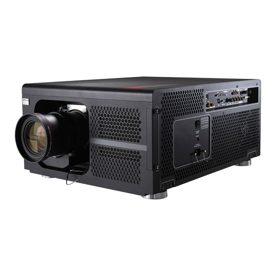
3. Projector parts and Functions 3. PROJECTOR PARTS AND FUNCTIONS Overview • Projector front view • Projector Rear view • Input and Communication • Status lights of LED • Connecting the projector to other devices 3.1 Projector front view Ventilation slot The hot air generated inside the projector is dispersed through the... -
Page 21: Input And Communication
3. Projector parts and Functions 3.3 Input and Communication 200mA . HDBaseT Supports Full HD uncompressed video transmission from image devices compatible with HDBaseT. Audio and network are not supported. For network connection refer to Page 14 "6. 10/100 BASE-T" 2. - Page 22 3. Projector parts and Functions 4. IR EXT. Receives input signal from compatible Niles or Xantech IR repeater systems. 5. YUV1 Standard and high definition (480i/480p/576i/576p/720p/1080i/1080p) component input, connects to DVD/HD-DVD/BD player, HD set-top-box or other SD/HD input source.Also connects to RGB input from RGBS input source. 6.
-
Page 23: Status Lights Of Led
3. Projector parts and Functions 3.4 Status lights of LED MENU ERROR STBY STBY INPUTS STAND BY Turns blue Indicates that the projector is in standby mode; this also means the p rojector has not been turned on by pressing the SOFT POWER button but has been connected to power. The indicator is off This indicates that the projector has either been turned on and is working normally or the projector is not connected to power. -
Page 24: Connecting The Projector To Devices
3. Projector parts and Functions 3.5 Connecting the projector to devices HDBaseT Supports Full HD uncompressed video transmission from image devices compatible with HDBaseT. Audio and network are not supported. For network connection refer to Page 14 "6. 10/100 BASE-T" Hi-Def Source 200mA HDBaseT... - Page 25 3. Projector parts and Functions 12V Trigger connection If your home theatre system includes a projector screen, screen cover or other 12V Trigger equipment, please connect such device/equipment to the projector’s 12V Trigger output as illustrated.After you have done so, Your screen will lower automatically whenever you turn on your projector for your convenience.
- Page 26 3. Projector parts and Functions VGA connection Connect your PC or other devices with VGAoutput to the VGAinput connectors on the projector to be used as the source of image input. 200mA Desk Top or Notebook 連接至牆壁插座 AC POWER AC MAINS SWITCH 100-240 Volts 50/60Hz...
- Page 27 3. Projector parts and Functions IR INPUT connection If the projector is unable to pick up the IR signals from the remote controle due to distance or obstacles (i.e. wall or cabinet doors), you can connect an external IR repeater to the projector’s IR INPUT jack to extend the effective signal reception range. IR sensor Remote control IR repeater...
- Page 28 3. Projector parts and Functions 10/100 BASE-T Connects the projector to your PC via network to have direct control of the projector from the PC. Desk Top or Notebook Stereo DVI Connect the Stereo DVI to a stereo 3D source - it is usually a computer with 3D Graphics card and 3D applications. IR Emitter 3D Glasses EMITTER L/R signals...
- Page 29 3. Projector parts and Functions 3D with a Barco RLM W14 1. You need: RLM W14 + ImagePRO II with option "dual output card. 3rd party IR Transmitter and 3D glasses. 2. Connection: Connect the DVI out ImagePRO II to DVI connector (3D) of RLM W14.
-
Page 30: Physical Installation
4.Physical Installation 4. PHYSICAL INSTALLATION About this projector This chapter describes how the mechanical set up of the projector has to be done and how to realize the electrical connections. Overview • Remote control unit (RCU) • Lenses • Connecting the projector with the power net • Alignment of a table mounted projector • Mounting the ceiling mount 4.1 Remote control unit (RCU) - Page 31 4.Physical Installation Remote Control overview INPUT ASPECT MENU RATIO IR LED’S AUTO IMAGE PAUSE TEXT SHARPN PHASE COLOR TINT SWAP ADDRESS Wired remoted connect to IR Ext. Basic Remote Command RCU action Remark result start the projector press "on" turn off the projector press "off"...
- Page 32 4.Physical Installation Basic Remote Command RCU action Remark result return to previous menu without press "menu" MENU selecting move through menu press "arrow keys" The enter button selects a item when in the menu. select button press "enter" When not in the menu the enter button will activate the lens adjust function.
- Page 33 4.Physical Installation Range of effective remote control signal reception The diagram below illustrates the range of effective remote control signal reception. 40° 40° Avoid placing the remote control at places of high temperature or humidity as it could cause the remote control to malfunction.
-
Page 34: Lenses
4.Physical Installation 4.2 Lenses Available lenses for the RLM W14 projector projector • R9862000-TLD+ (0.73:1) • R9801414-TLD+ (0.8 - 1.16:1) • R9840776-TLD+ (1.2:1) • R9862010-TLD+ (1.5 - 2.0:1) • R9862020-TLD+ (2.0 - 2.8:1) • R9862030-TLD+ (2.8 - 4.5:1) • R9862040-TLD+ (4.5 - 7:5:1) • R9829997-TLD+ (7.5 - 11.2) • R9862005-TLD+ Ultra (1.25-1.6) Projection lenses are optional accessories. -
Page 35: Installing The Lens With Safety Cable On An Rlm Projector
4.Physical Installation 5. Install a U-bolt on the lens holder, with the open ends oriented outwards (reference 3). Make sure that both a part of the loop end and the outgoing part of the safety cable are placed in the enclosure. 6. - Page 36 4.Physical Installation Make sure to hold the lens lever fully when install the lens (or remove the lens) AUTION: Never transport the projector with a Lens mounted in the Lens Holder. Always remove the Lens before transporting the projector. Neglecting this can damage the Lens Holder and Prism. It’s recommended to place the Lens caps of the original Lens packaging, back on both sides of the removed Lens to protect the optics of the Lens.
- Page 37 4.Physical Installation This illustration shows normal vertical lens shift without the use of special specification lens or projector. Please make sure the center of lens is retangular to the center of the screen. • Moving the lens horizontally The distance of horizontal lens movement is 30% of half the screen width in both directions. For instance, if you are using a 80"...
-
Page 38: Connecting The Projector With The Power Net
4.Physical Installation 4.5 Connecting the projector with the power net AUTION: Use only the power cord provided with the projector. 1. Ensure that the power switch stands in the ’0’ (OFF) position (1). 2. Tear off the warning label (2) 3. -
Page 39: Alignment Of A Table Mounted Projector
4.Physical Installation AUTION: Once the projector is switched to standby, the lamp cooling fans will continue to run for approx- imately five minutes to ensure that the projector and lamp have sufficiently cooled, at which point the fans will automatically decrease to standby. To avoid thermal stress that can lead to premature lamp failure, never unplug the power cord while the lamp cooling fans are running. -
Page 40: Mounting The Ceiling Mount
4.Physical Installation 4.7 Mounting the Ceiling mount Necessary tools Open wrench 17 mm How to mount 1. Turn the projector upside down. 2. Adjustment knob to the back of the projector. Make sure that the mounting holes matches the holes in the projector. 3. -
Page 41: Getting Started
5. Getting Started 5. GETTING STARTED Overview • RCU & Local keypad • Power on projector • Switching to standby • Power off projector • Range of effective remote control signal reception • Source selection • Changing OSD language • Adjusting the lens by horizontal and vertical lens shift 5.1 RCU &... -
Page 42: Switching To Standby
5. Getting Started 5.3 Switching to standby How to switch to standby 1. Press Power button on keypad or remote control for 3 seconds for projector to go into standby. 2. Wait until the projector completes the cooling process – at least 3~5 minutes. 3. -
Page 43: Adjusting The Lens By Horizontal And Vertical Lens Shift
5. Getting Started 5.7 Adjusting the lens by horizontal and vertical lens shift There has 2 methods to adjust the lens horizontal and vertical shift. Refer to below message. MENU ▼ ▲ • Press the button on the remote control and choose Alignment Lens Control; then use the buttons to adjust the horizontal or vertical position of the lens. -
Page 44: Osd Menu
6. Introduction the OSD menu 6. OSD MENU Overview The OSD menu is to control and align the projector, the following functions can be done: • OSD introduction. • Input setup: different Input settings can be adjusted such as specific input slot settings, locking, native resolution and no signal settings. -
Page 45: How To Navigate In The Osd Menu Structure
6. Introduction the OSD menu 6.1 How to navigate in the OSD menu structure? Once in the OSD menu structure, use the key on the remote control or on the local keypad to scroll through the items in the displayed menu. The selected item will get a background color. To activate a selected submenu or function, press on the remote or ENTER on the projector. -
Page 46: Input
7.Input 7. INPUT Overview • Input menu overview • Input Selection • Input Locking • Auto Power Off • Auto Power On • No Signal • Auto Image Adjust 7.1 Input menu overview HDMI HDBaseT RGB D-15 Input Selection YUV1 RGBHV/YUV2 SDI/HDSDI/3G Stereo DVI... -
Page 47: Input Selection
7.Input 7.2 Input Selection Use this function to specify the source of image connected to the rear of the projector. For instance, if you have connected your PC as the video input source, you can choose RGB D-15(RGB-HV/SOG) to be the input for image projection. Options of HDMI1, HDMI2, RGB D-15(RGB-HV/SOG), YUV1(RGB-S), YUV2(RGBHV/ input available on the projector include: YUV2), SDI/HDSDI/3G, Stereo DVI. -
Page 48: Auto Power Off
7.Input 7.5 Auto Power Off The default value is OFF. If you set it to ON, the projector will automatically shut down after 20 minutes without input signal. 7.6 Auto Power ON The default value is Off.If you set it to ON, the projector will automatically start up when it is connected to AC power. If you plug the projector’s power cord into an AC socket with a switch, you can use this function to start up the projector using the socket’s switch instead of the remote. -
Page 49: Image
8.Image 8. IMAGE Overview • Image menu overview • Contrast • Brightness • Sharpness • Noise Reduction • Color Temperature • Input Balance • Aspect Ratio • Timings • Auto Image 8.1 Image menu overview Contrast 0~200 Brightness 0~200 Sharpness 0~200 Noise Reduction 0~200 3200K... -
Page 50: Contrast
8.Image RLM W14 8.2 Contrast The contrast function is used to adjust the contrast between the light and the dark areas of the displayed image. It applies a gain to the red, green and blue signals. Contrast adjustment can be done with the Contrast key on the RCU or via the menu structure. The following image illustrates the results of direct contrast adjustment using a random image: Lowered contrast Original image... -
Page 51: Sharpness
8.Image 8.4 Sharpness The adjustment of sharpness primarily changes the value of high frequency detail. You can connect the projector to an external image source to display an image resembling the one shown below to adjust the image sharpness. The following image illustrates the results of direct sharpness adjustment using a random image: Reduced sharpness Original image Enhancedsharpness... -
Page 52: Input Balance
8.Image 8.7 Input Balance Regardless of the change in ambient light, the human eye is equipped with an automatic adjustment mechanism that makes a white object appears white and black object black.However, since no machine has such an incredible innate feature, you may need to make certain adjustments to the projector’s settings when the ambient light changes so that the image will appear closer to the actual colors. -
Page 53: Aspect Ratio
8.Image 8.8 Aspect Ratio Relation between the horizontal & vertical dimension in which the window will be displayed, e.g. 4 by 3 or 16 by 9. Can also be expressed as a decimal number, such as 1.77. The larger the ratio or decimal, the wider the image (or the less the image is squared). -
Page 54: Timings
8.Image Native input Output aspect ratio Output aspect ratio Output aspect ratio 16:9 Output aspect ratio Output aspect ratio Output aspect ratio Output aspect ratio 1.88 2.35 Letterbox Native Cropped portion of the image that when used for commercial purposes, including: projection of image in movie theatres, hotels, cafeteria and other public venues, compression or extension of image achieved through the change of aspect ratio may constitute copyright infringement to the rightful owner of the image. - Page 55 8.Image H Start to adjust the projected image’s horizontal position. If the projected image is not at the center of the screen (i.e. shifted to right or left) and ends up being cropped, use this function to adjust the image’s horizontal position.The following image is an example of test image from an external signal source: Native picture...
-
Page 56: Auto Image
8.Image 8.10 Auto Image When Auto Image was selected in the OSD menu, press to execute the automatic image adjustment function. By executing this function, the projector will resync the image. Use this function when the image source is unstable or when you notice deterioration in image quality and the projector will automatically adjust the image size, phase and timing. -
Page 57: Layout
9.Layout 9. LAYOUT Overview • Layout menu overview • Zoom • Main Select • PIP Select • PIP Position • PIP 9.1 Layout menu overview Zoom Crop Zoom HDMI HDBaseT RGB D-15 Main Select YUV1 RGBHV/YUV2 SDI/HDSDI/3G Stereo DVI HDMI LAYOUT HDBaseT RGB D-15... -
Page 58: Zoom
9.Layout 9.2 Zoom Due to the fact that some consumers may still be using older television systems, some TV programs may not display the edges of the image. Use this function to hide the image edge by choosing one of the following three options: • Off Setting it to off makes no change to the projected image. -
Page 59: Pip Select
9.Layout 9.4 PIP Select Use this function to select the source for the sub window. Main picture Sub picture You can choose from HDMI1, HDMI2, VGA, YUV1, RGBHV/YUV2. PiP stands for "Picture in Picture" and allows to display multiple windows containing each of them an image. -
Page 60: Lamp
10.Lamp 10. LAMP Overview • Lamp menu overview • Lamps Single and Dual setup • High Altitue Mode setup • Power saving setup • Lamp1 and Lamp2 on or off setup • Lamp1 and Lamp2 Run Time display • Lamp Performance 10.1 Lamp menu overview Mode Normal... -
Page 61: Mode
10.Lamp 10.2 Mode This chapter covers information on the projector lamp. Mode • ECO When set to Eco mode, the wattage of the lamp will be at 360W. If the surrounding environment is sufficiently dark or if you do not require intense brightness, you can set the lamp to Eco mode to prolong its usage life. • Normal When set to Normal mode, the wattage of the lamp will be at 465W. -
Page 62: High Altitude Mode
10.Lamp 10.4 High Altitude Mode Use this function to control the projector's cooling fan. You can set it to Off or On. The default setting is Off. Under normal circumstances, the projector will operate normally with this function set to Off. By default, the projector will detect the temperature of the surrounding environment to regulate the speed of the cooling fan. -
Page 63: Alignment
11.Alignment 11. ALIGNMENT Overview • Alignment menu overview • Adjusting screen orientation(Rear Projection, Ceiling Mode on of off setup) • Lens Control for zoom, focus and V/H Shift setup • Keystone adjustment • Dynamic Contrast setup • Gammy adjustment • Internal Patterns setup • Custom Color Space select • Setup lens to midposition 11.1 Alignment menu overview... -
Page 64: Adjusting Screen Orientation
11.Alignment 11.2 Adjusting screen orientation By default, the projector is configured for “frontal projection - desktop installation”. If you choose to install your projector in other setups, be sure to adjust the screen orientation to achieve the correct projection mode. Front projection - ceiling mode Press MENU... -
Page 65: Rear Projection
11.Alignment Rear projection - ceiling mode Press MENU ALIGNMENT Rear Projection and choose ON; press MENU once more ALIGNMENT Ceiling Mode and choose ON Correct Picture canoe 11.3 Rear Projection The default of the Rear Projection setting is Off. See 11.2 Adjusting screen orientation, refer to page 56: 11.2 Adjusting screen orientation 11.4 Ceiling Mode... -
Page 66: Lens Memory
11.Alignment 11.8 Lens Memory There are three functions available after adjusting zoom, focus and lens shift position. Save Memory it is used to store current zoom, focus, and lens shift position settings into the designated memory among 3 memories. Users can repeat the above procedure to store up to 3 lens memories. -
Page 67: Color Space
11.Alignment 11.12 Color Space Using different color space will create different color presentation in the projected image. You can choose from the following color gamma: Native Choose this to apply the projector's native color gamut Choose this to apply the EBU color gamut; it is primarily suited for input devices using PAL, SECAM, 576i, 576p and so forth. SMPTE Choose this to apply the SMPTE color gamut;... - Page 68 11.Alignment Vertical Keystone Press to correct Vertical keystone due to projection angle. —> The summation of the absolute value of horizontal keystone and vertical keystone is limited to less than or equal to 350. Rotation Press to correct incorrect image angle. Press ...
- Page 69 11.Alignment Top Left Corner Press to correct top left corner image bias. —> Press to correct Top left corner image bias to correct image. Top Right Corner Press to correct top right corner image bias. —> Press to correct Top Right corner image bias to correct image.
-
Page 70: Blanking
11.Alignment 11.15 Blanking Press on the remote control to adjust the top blanking area on the projected image Bottom Press on the remote control to adjust the Bottom blanking area on the projected image Left Press on the remote control to adjust the Left blanking area on the projected image Right Use left blanking... - Page 71 11.Alignment Black Level The purpose of black level is in order to compensate the non overlap zones vs the over lap zone. It increase the black level to the brightness level of the overlap black. It is to adjust the black level of the Top, Bottom, Left, Right direction on the projected images.
- Page 72 11.Alignment Adjust Lines When the function is ON, there will be adjust lines on the image in order to easily adjust multiple images. Press on the remote control to adjust the position of the lines on the image. The image below is an example if 2 projectors are projecting at the same image. 1.
-
Page 73: Control
12.Control 12. CONTROL Overview • Control menu overview • ECO Network Power setup • Network address setup • OSD Menu position • Projector start up display Logo or not • Projector start up Chime on or off • Setup the trigger • Setup the projector auto select the source or not • Setup the OSD menu's language 12.1 Control menu overview... -
Page 74: Ir Address
12.Control 12.2 IR Address Use this function to configure the projector’s IR code receive commands from the remote control. The default value is 1.If you have other equipment in your home that could pick up the command from the projector’s remote control, it is recommended that you set the remote control code to 2. - Page 75 12.Control IP Address Internet Protocol. The network layer of TCP/IP. Required for communication with the internet. This for subnet and gateway hdcp. Subnet mask A number that is used to identify a subnetwork so that IP addresses can be shared on a local area network. Subnet for Wired and Wifi must be different ! Gateway A router that serves as an entry point into and exit point out of a network.
-
Page 76: Menu Position
Bottom Left Bottom Right 12.6 Start Up Logo You can use this function to have the projector display the Barco logo in the start up screen. Set to display the Barco logo during start up and to display a blank image. -
Page 77: Trigger1 ~2
12.Control 12.9 Trigger1 ~2 The projector comes with two sets of Trigger output. You can configure two different devices connected to the projector via the trigger ports to be automatically turned on when the projector is on. There will be a 2-3 second delay prior to activation to prevent operation of this function when the user is choosing the desired aspect ratio. -
Page 78: Service
13.Service 13. SERVICE Overview • Service menu overview • Use this function to display the projector's message. 13.1 Service menu overview Model Serial Number Software Version Active/PIP source Pixel Clock Read-only information Signal Format H/V Refresh Rate Lamp1 Run Time SERVICE Lamp2 Run Time Lamp1 Hour Reset... -
Page 79: Service Message Of The Projector
13.Service 13.2 Service message of the projector The functions covered in this unit relate to the display of some basic information about the projector. Memory of the custom timing files will be erased in the Factory Reset operation • Model: the designated model number of the projector. • Serial Number: the designated serial number of the projector. -
Page 80: Maintenance
14.Lamp and Filter Maintenance 14. MAINTENANCE 14.1 Lamp Replacement The lifecycle of ordinary projection lamp typically lasts for 2500 hours before requiring replacement (different lamp configurations will affect lamp life). From the OSD Menu, you can go to " page 54: 10.8 Lamp1 Run Time ". - Page 81 14.Lamp and Filter Maintenance 4. Grasp the metal rod on the lamp cover and pull the lamp out. 5. Insert the new lamp in the direction shown in the illustration into the lamp assembly; tighten the two screws using a screw diver and make sure the lamp is firmly secured to prevent the lamp from shaking or poor contact.
-
Page 82: Replace The Filter (For Inlet Ventilation)
14.Lamp and Filter Maintenance 14.2 Replace the filter (for inlet Ventilation) Make sure to replace the filter when it is required to keep the air intake clear of dust, and prevent possible over temperature issue of the projector due to the clog of filter. AUTION: The high density filter must be replaced on a regular basis, depending on the environment condi- tions of the projector. - Page 83 14.Lamp and Filter Maintenance 3. Insert new filter. Black side White side White side Black side 4. Tighten the five screws of left side cover. RLM W14 17/04/2017...
-
Page 84: Clean The Dust Filter(For Outlet Ventilation)
14.Lamp and Filter Maintenance 14.3 Clean the dust filter(for outlet Ventilation) 1. Remove most contamination with a vacuum cleaner. 2. Blow remaining dust away with compressed air in an other room or outside. 14.4 Cleaning the lens To minimize the possibility of damage to optical coatings, or scratches to lens surfaces, we have developed recommendations for cleaning. -
Page 85: Simple Troubleshooting
14.Lamp and Filter Maintenance 14.6 Simple troubleshooting The following table offers a list of common problems with projectors and how to troubleshoot. If the recommended solutions fail to resolve your problem, contact your local dealer to arrange for servicing; do not attempt to service the projector by yourself. - Page 86 14.Lamp and Filter Maintenance Problem Possible cause Solution 1. The lens may not be in focus. 1. Adjust Lines focus. 2. The temperature or humidity of the 2. Turn of the projector first and wait for the projector's working environment may have moisture in the projector to evaporate.
-
Page 87: Projector Specification
15.Projector Specifications 15. PROJECTOR SPECIFICATION 15.1 Specifications Description Specifications Projector type 3-chip DLP projector Technology 0,96" DMD x 3 Resolution 1920 × 1200 (Native) Brightness 13500 ANSI lumen 14500 center Contrast ratio 1650 : 1 Brightness uniformity ANSI Aspect Ratio 16:10 Lens type TLD+ lens... -
Page 88: Standard Source Files
15.Projector Specifications 15.2 STANDARD SOURCE FILES HDMI / HDBaseT Frame Signal Resolution Format Rate 640×480 59.94 640×480 74.99 640×480 800×600 60.32 800×600 800×600 85.06 848×480 47.95 848×480 59.94 1024×768 1024×768 1024×768 1280×720 47.95 1280×1024 60.02 1280×1024 75.02 1280×1024 85.02 1600×1200 1920×1080 47.95 1680×1050... -
Page 89: Sdi Formats
15.Projector Specifications 15.3 SDI FORMATS Color Sampling Timing SDI Link mode Signal Standards Bit Depth Encode Structure NTSC SMPTE 259M-C 270Mbps SD YCbCr 4:2:21 1035i60 SMPTE 292M 1.5Gbps HD YCbCr 4:2:21 1080i59 SMPTE 292M 1.5Gbps HD YCbCr 4:2:21 1080i60 SMPTE 292M 1.5Gbps HD YCbCr 4:2:21 1080P30... -
Page 90: Environmental Information
Mercury Notice Lamp(s) Contain Mercury. Dispose According to Local, State, Federal Law. This Barco product consists of materials that may contain mercury, which must be recycled or disposed of in accordance with local, state, or country laws: • Within this system, the lamp in the projector contains mercury. 16.2 Rohs compliance Turkey RoHS compliance Türkiye Cumhuriyeti: EEE Yönetmeli ine Uygundur. - Page 91 16.Environmental information 本产品中包含的有毒有害物质/成分的名称和含量。 RLM W14 17/04/2017...
Need help?
Do you have a question about the R9006332B1 and is the answer not in the manual?
Questions and answers