Crestron FT-TS600 FlipTop User Manual
Hide thumbs
Also See for FT-TS600 FlipTop:
- Operations & installation manual (40 pages) ,
- Supplemental manual (16 pages)
Advertisement
DO
GUIDE
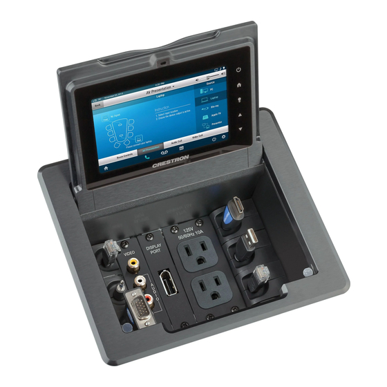
FT-TS600
FlipTop™ Touch Screen
DO
Install the Device
Installing the Bushings
The Crestron
FT-TS600 ships with two cable management
®
plates preinstalled. These provide a pullout cable solution for
the AUD OUT (audio output), COMPUTER, and LAN cables. A
6 foot (1.8 meter) USB type A to type B cable is included for
the COMPUTER connection. Cables are looped through the
cable management plates.
The included bushings must be installed before mounting the
FT-TS600 into a surface. For a neat appearance, any unused
openings can be filled using the included hole plugs. The only
tool required to install the bushings is a Phillips screwdriver.
1. Remove the two cable management plates and retain the
two 06-32 x 1/4" screws.
2. Place the bushings on the cables (eight bushings
supplied).
3. Thread the cables through the appropriate slots in each
cable management plate.
4. Snap the bushings into the cable management plate
slots.
5. Feed all excess cable through the bushings.
6. Attach each cable management plate by sliding the
dovetail into the slot shown below, dropping the front
of the cable management plate into place, and then
securing the cable management plate with the
06-32 x 1/4" screw from step 1.
The cable management
plate dovetail inserts here.
Bushing
Cable Management Plates (2)
Screws (2) 06-32 x 1/4"
DO
QTY PRODUCT
2
4
4
4
Mounting into a Surface
4
The FT-TS600 is designed
4
to mount into a horizontal
1
surface, such as a desktop,
lectern, or podium. The
1
following diagram illustrates
1
the required cutout dimensions
to accommodate the
FT-TS600.
7 1/2"
(190 mm)
Maximum
6 1/4"
Radius
(159 mm)
1/8"
(4 mm)
NOTE:
Before inserting the FT-TS600 into the mounting hole,
ensure that all require cables have been installed.
The only tools required are a Phillips screwdriver and a #10
Allen wrench. To mount the FT-TS600, use the following
procedure:
1. Position the FT-TS600 in the mounting hole.
2. Install the four included 10-32 x 2" socket screws in the
metal mounting plates (two screws per plate).
3. Slide the moutning plates over the studs on each side of
the FT-TS600.
Check the Box
Mounting Plates
Screws, 10-32 x 2", Socket
Small Hole Plugs
Large Hole Plugs
Small Bushings
Large Bushings
Connector, 3-Pin
Cable, USB 2.0, A-B, 6' (1.8 m)
Cutout Template
4. Turn the four 10-32 x 2" socket screws equally until they
contact the underside of the mounting surface.
NOTE: Do not overtighten the screws because this may
damage the surface or the unit.
Mounting Surface
PART NUM.
2036985
2037109
2036647
2036649
2009522
2010496
2003575
2014966
4519221
Studs for the
Mounting Plate
Surface Cutout
Mounting Plates
Screws (4) #10-32 x 2"
Advertisement
Table of Contents

Related Manuals for Crestron FT-TS600 FlipTop


Summary of Contents for Crestron FT-TS600 FlipTop
- Page 1 2009522 Installing the Bushings The FT-TS600 is designed Large Bushings 2010496 to mount into a horizontal The Crestron FT-TS600 ships with two cable management ® Connector, 3-Pin 2003575 surface, such as a desktop, plates preinstalled. These provide a pullout cable solution for lectern, or podium.
- Page 2 However, there is no guarantee that interference will not to refer to either the entities claiming the marks and names or their products. Crestron disclaims any proprietary interest in the marks and names of others. Crestron is not responsible for occur in a particular installation.
Need help?
Do you have a question about the FT-TS600 FlipTop and is the answer not in the manual?
Questions and answers