Keysight u1272a Quick Start Manual
Handheld
Hide thumbs
Also See for u1272a:
- Quick start manual (193 pages) ,
- User manual (188 pages) ,
- Service manual (63 pages)
Table of Contents
Advertisement
Quick Links
Advertisement
Table of Contents

Related Manuals for Keysight u1272a


Summary of Contents for Keysight u1272a
- Page 1 Keysight U1271A/U1272A Handheld Digital Multimeter Quick Start Guide...
- Page 3 One K-type thermocouple lead kit ✔ Four 1.5 V AAA alkaline batteries ✔ Printed copy of the U1271A/U1272A Quick Start Guide ✔ Printed copy of the Certificate of Calibration If any item is missing or damaged, keep the shipping materials and contact the nearest Keysight Sales Office.
-
Page 4: Install The Batteries
Your multimeter is capable of remote data logging. To use this NO TE feature, you will need an IR-USB cable (U1173A, purchased separately) and the Keysight GUI Data Logger Software (down- loadable from www.keysight.com/find/hhTechLib). U1271A/U1272A Quick Start Guide... -
Page 5: The Multimeter At A Glance
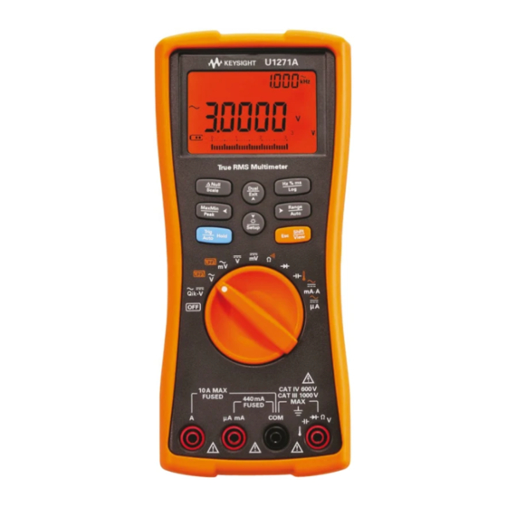
U1271A/U1272A Handheld Digital Multimeter The Multimeter at a Glance The Multimeter at a Glance Display screen Keypad Rotary switch Input terminals Test lead/probe holders IR communication port Battery access cover Tilt stand U1271A/U1272A Quick Start Guide... -
Page 6: Understanding The Rotary Switch
Resistance/Continuity/(Smart , U1272A only) Smart Diode/(Auto-diode, U1272A only) Auto Capacitance/Temperature AC, DC, or (AC+DC mA and A, U1272A only) AC, DC, or (AC+DC A, U1272A only) AC/DC V check for signal identification (U1271A only) Qik-V (low input impedance) AC/DC V for checking... -
Page 7: Understanding The Keypad
U1271A/U1272A Handheld Digital Multimeter Understanding the Keypad Understanding the Keypad Key response when pressed for: Legend Less than 1 second More than 1 second Sets the Scale mode for Sets the Null/Relative the specified ratio and mode. unit display. Starts and stops the Starts and stops the MaxMin recording. -
Page 8: Understanding The Input Terminals
U1271A/U1272A Handheld Digital Multimeter Understanding the Input Terminals Understanding the Input Terminals Ensure that the terminal connections are correct for that WA RN ING particular measurement function before starting any measurement. To avoid damage to the device, do not exceed the input limit. -
Page 9: Voltage Measurements
U1271A/U1272A Handheld Digital Multimeter Performing Measurements and Tests Performing Measurements and Tests Voltage measurements The figure below highlights the primary functions allowing voltage measurements in your multimeter. U1271A U1272A Set up your multimeter as shown in the figure below to per- form voltage measurements. - Page 10 U1271A/U1272A Handheld Digital Multimeter Performing Measurements and Tests 1 Press for more than 1 second to enter the multimeter’s Setup setup menu. 2 Press until is shown on the secondary display. Dual 3 Press to enable the Filter. Exit Setup Refer to the table below for the respective firmware ver- sions.
- Page 11 U1271A/U1272A Handheld Digital Multimeter Performing Measurements and Tests measurements (U1272A only): Rotate the rotary switch’s position to to enable low impedance mea- surements. • Use the Z (low input impedance) function to detect ghost or induced voltages. • Ghost voltages can be caused by capacitive coupling between energized wiring and adjacent unused wiring.
-
Page 12: Resistance Measurements
Performing Measurements and Tests Resistance measurements Set up your multimeter as shown in the figure below to per- form resistance measurements. Smart Smart measurements (U1272A only): While performing resistance mea- surements, press until is shown on the display to enable the Smart ... -
Page 13: Continuity Tests
U1271A/U1272A Handheld Digital Multimeter Performing Measurements and Tests Continuity tests Set up your multimeter as shown in the figure below to per- form continuity tests. Press to switch to the continuity test function ( is shown on the display). You can set the beeper to sound and the backlight to flash as a... -
Page 14: Diode Tests
U1271A/U1272A Handheld Digital Multimeter Performing Measurements and Tests Diode tests Set up your multimeter as shown in the figure below to per- form diode tests. Auto Auto-diode tests (U1272A only): Press until is shown on the display to use the auto diode function. -
Page 15: Capacitance Measurements
U1271A/U1272A Handheld Digital Multimeter Performing Measurements and Tests Capacitance measurements Set up your multimeter as shown in the figure below to per- form capacitance measurements. is shown on the bottom left of the display when the capaci- NO TE tor is charging, and is shown when the capacitor is dis- charging. -
Page 16: Temperature Measurements
U1271A/U1272A Handheld Digital Multimeter Performing Measurements and Tests Temperature measurements Set up your multimeter as shown in the figure below to per- form temperature measurements. Do not connect the thermocouple to electrically live WA RN ING circuits. Doing so will potentially cause fire or electric shock. -
Page 17: Current Measurements
U1271A/U1272A Handheld Digital Multimeter Performing Measurements and Tests Current measurements Set up your multimeter as shown in the figure below to per- form current measurements. Press to switch between AC, DC, AC+DC, or % scale current measurements. When mea- suring DC current from a mixed signal in DC measurement mode, ensure that the Filter ( ) is enabled. - Page 18 U1271A/U1272A Handheld Digital Multimeter Performing Measurements and Tests U1271A/U1272A Quick Start Guide...
-
Page 19: Safety Information
• China Call Center: 800-810-0189 • Europe Call Center: 31-20-547-2111 • Japan Call Center: (81) 426-56-7832 For other countries, contact your country’s Keysight support organization. A list of contact information for other countries is available on the Keysight Web site: www.keysight.com/find/assist Safety Notices... - Page 21 This information is subject to change without notice. © Keysight Technologies 2010 – 2014 Edition 5, August 2014 *U1271-90000* U1271-90000 www.keysight.com...
Need help?
Do you have a question about the u1272a and is the answer not in the manual?
Questions and answers