Table of Contents
Advertisement
Quick Links
Download this manual
See also:
Owner's Manual
Advertisement
Table of Contents

Subscribe to Our Youtube Channel
Related Manuals for SportsArt Fitness S770


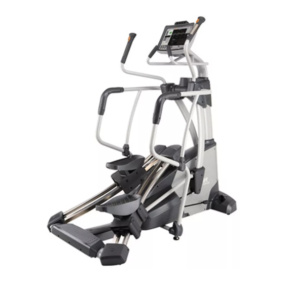
Summary of Contents for SportsArt Fitness S770
- Page 1 S770 Repair Manual (Mechanics)
-
Page 2: Table Of Contents
1-1-1. Blowup Diagram - S770 (Continued on 1-1-4) 2-1-1. Basic Adjustments - S770 Leveling 2-1-2. Basic Adjustments - S770 Elastic Cord Adjustment 2-2-1. Unit Maintenance - S770 Foot Carriage Roller Maintenance 2-2-2. Basic Maintenance - S770 Foot Carriage Lubrication 2-2-3. Basic Maintenance - S770 Daily Cleaning 3-1-1. -
Page 3: Blowup Diagram - S770 (Continued On 1-1-4)
1-1. Blowup Diagram - S770 1-1-1... - Page 4 1-1. Blowup Diagram - S770 1-1-2...
- Page 5 1-1. Blowup Diagram - S770 1-1-3...
- Page 6 1-1. Blowup Diagram - S770 1-1-4...
- Page 7 1-2. Mechanical Component Introduction - S770 Cable pulley Motion rod Knob belt Footplate carriage Elastic cord Glide track Idler pulley Alternator/Flywheel Drive axle 1-2-1 Knob belt and pulleys 1-2-1...
-
Page 8: Basic Adjustments - S770 Elastic Cord Adjustment
2-1. Basic Adjustments - S770 Elastic Cord Adjustment Elastic cord adjustment 1. Open the cover. Adjust elastic cord as desired. Use zip ties to secure the elastic cord. Reinstall the cover. 2. Adjust both sides equally at the same time. - Page 9 2-1. Basic Adjustments - S770 Alternator Belt Adjustment Step 1. Loosen the screw shown below. Press down on the alternator. The screw position will become lower. And the belt will tighten. Step 2. As you assert pressure on the alternator, secure the screw. After making the adjustment, inspect unit operation for noise and other issues.
-
Page 10: Unit Maintenance - S770 Foot Carriage Roller Maintenance
2-2. Unit Maintenance - S770 Foot Carriage Roller Maintenance Step 1: Lubricate inner and outer diameter of roller bearings. Step 2: On the axle, brush on at least 1mm thick of lubricant. 2-2-1... -
Page 11: Basic Maintenance - S770 Foot Carriage Lubrication
2-2. Basic Maintenance - S770 Foot Carriage Lubrication Step 3: Step 4: Step 5: Use a brush to apply lubricant to Re-assemble, inserting the axle Wipe off excess lubricant. inner diameter holes of the foot from the exterior. (Insert wave Then install the washer and carriage. -
Page 12: Basic Maintenance - S770 Daily Cleaning
2-2. Basic Maintenance - S770 Daily Cleaning Use a dry cloth to wipe sweat Use a dry cloth to wipe sweat from the handle arms. Daily from the display. Daily Use a dry cloth to wipe sweat from the supports. Daily Use a dry cloth to wipe sweat from handles. -
Page 13: Mechanical Component Inspection
3-1. Mechanical Component Inspection Item Part Inspection Note Optic sensor 1. Make sure the optic sensor is within 4-5mm from the reflective sticker. Knob belt/Elastic cord 1. Make sure the knob belt is in the center of its pulley. 2. Make sure the elastic cord isn’t too loose and sagging. Adjust if necessary. Pulley cable 1. -
Page 14: Mechanical Troubleshooting Chart
3-2. Mechanical Troubleshooting Chart Item Issue Remedy Note Unit wobbles or rocks 1. Inspect and adjust levelers. during use. Foot carriage locks up 1. Inspect whether the black, O-shaped spacer beside the rollers fell out of place, with heavy resistance getting caught. -
Page 15: Component Inspection - Alternator
3-3-1. Component Inspection - Alternator Inspect alternator belt tightness. ( If too loose, loosen screw A, press down on the alternator to pull the belt tight, then secure screw A again. Exercise briskly to inspect whether the alternator belt jumps the channel. (If it does so, inspect and adjust the alternator bracket angle.) -
Page 16: Component Inspection - Flywheel
3-3-2. Component Inspection - Flywheel Make sure the flywheel belt operates in the center of its pulley without jumping off track. Make sure that the flywheel belt and idler pulley belt are on track and not tending toward one side or the other. -
Page 17: Component Inspection - Knob Belt And Elastic Cord
3-3-3. Component Inspection – Knob Belt and Elastic Cord Make sure the knob belt operates properly without jumping track. Inspect pulley operation. Inspect whether the elastic cord has jumped track. Inspect the distance between the optic sensor and the reflective sticker. -
Page 18: Component Inspection - Foot Carriage, Glide Track
3-3-4. Component Inspection – Foot Carriage, Glide Track Exercise on the unit. Does the foot carriage roller glide smoothly? If not, inspect whether the roller is dirty. Clean it as needed. Exercise on the unit. Does the foot carriage roller get stuck? If not, inspect the black, O-shaped spacer. -
Page 19: Component Removal And Installation-Drive Board/Battery Removal
4-1. Component Removal and Installation–Drive Board/Battery Removal Step 2 Step 1 Remove cover screws and the cover. Remove covers shown below. Step 3 This is all it takes to access the drive board and battery. Reinstall parts in reverse order. 4-1-1... - Page 20 4-2. Component Removal and Installation – Lower Cover Removal Step 2 Remove 4 screws shown below. Then Step 4 remove supports. Remove supports on Remove central pulley cover screws both sides in the same way. and washers. Step 3 Step 1 Remove soft caps and screws.
- Page 21 4-2. Component Removal and Installation –Lower Cover Removal, Cont. Step 6 Step 8 After removing screws, remove the Remove screws and remove large pulley covers. side covers on both sides. Step 7 Step 5 Remove the small cover shown Remove screws and remove covers on here.
- Page 22 4-2. Component Removal and Installation –Lower Cover Removal, Cont. Step 9 This picture shows the product with lower covers removed. Install covers by following these steps in reverse. 4-2-3...
-
Page 23: Component Removal And Installation - Alternator Removal
4-3. Component Removal and Installation – Alternator Removal Step 1 Detach the alternator wires. Step 2 Loosen screws and remove the alternator. 4-3-1... -
Page 24: Component Removal And Installation - Alternator Installation
4-3. Component Removal and Installation – Alternator Installation Step 1 Put the belt on the alternator and set the alternator in place. Thread screws into place. Press down on the alternator to tighten the belt. Fully secure the screws. Step 3 Connect alternator wires as shown. - Page 25 4-4. - Component Removal and Installation–Knob Belt & Elastic Cord Removal Step 1 Step 2 Stretch the elastic cord off the pulley. Then Remove the optic sensor screws. Remove remove the screw shown below. the sensor. Then remove the knob belt. Step 3 Step 4 Remove screws on the cover shown below.
- Page 26 4-4. - Component Removal and Installation – Knob Belt & Elastic Cord Step 5 Removal Remove screws that secure knob belt hardware. The knob belt is then free for removal. 4-4-2...
- Page 27 4-4. - Component Removal and Installation – Knob Belt & Elastic Cord Installation Step 1 Step 2 Inspect the elastic cord/knob belt Reinstall the elastic cord as shown. Secure connection. Make sure zip ties secure the screws. connection as shown. 4-4-3...
- Page 28 4-4. - Component Removal and Installation – Knob Belt & Elastic Cord Installation Step 4 Step 3 Install the knob belt as shown. Install the belt and secure its connector hardware. Step 5 Install the elastic cord on its pulley as shown.
-
Page 29: Component Removal And Installation - Drive Axle Removal
4-5. Component Removal and Installation – Drive Axle Removal Step 2 Step 1 Remove the drive belt from its pulley. Remove the elastic cord from the pulley. Step 3 Remove nuts and screws as shown. Remove axle end hardware (pillow block bearing set). -
Page 30: Component Removal And Installation - Drive Axle Installation
4-5. Component Removal and Installation – Drive Axle Installation Step 1 Knob belt pulley (or gear set) drive axle Insert knob belt pulleys (belt drive gear sets) on both sides. Insert machined edge facing the left side. (車削部份) 4-5-2... - Page 31 4-5. Component Removal and Installation – Drive Axle Installation Step 2 Step 4 Reinstall the spring washer and axle end After installing the axle, re-install belts hardware (pillow block bearing set). into place. Step 3 Step 5 On axle end hardware (pillow block Install the axle and end hardware (pillow bearing sets) install C-clips as shown.
- Page 32 4-5. Component Removal and Installation – Drive Axle Installation Step 6 Step 8 Put the flywheel belt in place. Inspect belt positioning. Belt must run in the center of the drive pulley. Test unit operation to inspect belt operation. Step 7 Step 9 Install the idler pulley and belt.
- Page 33 4-5. Component Removal and Installation – Drive Axle Installation Step 10 Put the elastic cord in place on its pulleys. 4-5-5...
-
Page 34: Component Removal And Installation - Flywheel And Belt Removal
4-6. Component Removal and Installation – Flywheel and Belt Removal Step 2 Remove nuts and screws shown below to remove the flywheel. See bottom. Step 1 To remove the flywheel, first remove the alternator. 4-6-1... -
Page 35: Component Removal And Installation - Flywheel And Belt Installation
4-6.Component Removal and Installation–Flywheel and Belt Installation Step 1 Set the flywheel in place and secure screws and nuts shown below. Step 3 Inspect alternator and belt installation. Exercise on the unit. Belts should run in the center of their channels, without tending toward one side or another. - Page 36 4-7. Component Removal and Installation – Cable Removal Step 1 Step 3 Remove pulley covers as shown. Remove the screw indicated here. Step 4 Use needle-nosed pliers to remove the screw (which serves as the cable end pin) from underneath. Step 2 Set one foot carriage in the lowest position, the other in the highest.
-
Page 37: Component Removal And Installation - Cable Removal (Continued To 4-7-2)
4-7. Component Removal and Installation – Cable Removal, Continued Step 6 Step 5 Remove screws here to detach the cable Remove this cable end. Detach the other from the pulley. cable end in the same way. 4-7-2... - Page 38 4-7. Component Removal and Installation – Cable Installation Step 2 Use needle-nosed pliers to insert the screw Step 1 (which serves as the cable end pin) from Insert the PE washer into the cable end loop below. as shown. Step 3 Secure this screw.
- Page 39 4-7. Component Removal and Installation – Cable Installation Step 4 Step 5 Insert the cable into the pulley channel. Re-install the pulley covers. Then secure the two screws shown here. 4-7-4...
- Page 40 4-8. Component Removal and Installation–Foot Carriage and Glide Track Removal Step1 Step 2 Follow instructions above to disconnect Remove screws indicated below to remove the cables and the motion rod. Then remove glide track. covers A & B indicated below. Step 3 This shows the glide track removed.
- Page 41 4-8. Component Removal and Installation – Foot Carriage and Glide Track Removal Step 5 Lift the front and back parts of the foot cushion. Remove screws. Remove the foot plates. 4-8-2...
- Page 42 4-8. Component Removal and Installation – Foot Carriage and Glide Track Removal Step 7 Step 6 Remove the nut and roller axle pin to replace Remove screws and covers. side rollers. 4-8-3...
- Page 43 4-8. Component Removal and Installation – Foot Carriage and Glide Track Removal Step 9 Step 8 Remove the nut and axle pin to remove front Remove the footplate and front side cover. inner rollers. Remove screws and the footplate set plate. Step 10 Step 11 To replace the foot carriage or inner rollers,...
- Page 44 4-8. Component Removal and Installation – Foot Carriage and Glide Track Step 1 Step 3 Installation Before installing the foot carriage, tape glide Install components on the glide tracks. track ends as shown. Then slide the foot carriage onto the glide track. After installing the set plate, fully secure screws.
- Page 45 4-8. Component Removal and Installation – Foot Carriage and Glide Track Step 4 Step 5 Installation Secure the 6 set plate screws. Fully secure screws in the set plate. Set plate Step 7 Step 6 Secure the 6 screws at the lower set plate Secure components on the unit as shown.
-
Page 46: Component Removal And Installation - Optic Sensor Installation
4-9. Component Removal and Installation – Optic Sensor Installation Step 1 Secure optic sensor bracket screws. Step 2 Make sure the distance between the optic sensor and the reflective sticker is 4-5mm. 4-9-1... -
Page 47: Component Removal And Installation - Htr Contact Plate Removal
4-10. Component Removal and Installation – HTR Contact Plate Removal Step 1 Remove screws behind contact plates. Step 2 Remove the HTR contact plates. 4-10-1... - Page 48 4-11. Component Removal and Installation – Rocker Arm Removal Step 3 Step 1 Disconnect the wire shown here. Remove the covers. Step 4 Step 2 Remove the screw and sheath. Remove Remove the support. Then remove the the C-clip. knob belt connector. 4-11-1...
- Page 49 4-11. Component Removal and Installation – Rocker Arm Removal Step 5 Pull the arm straight out to remove it. Follow the procedure in reverse for assembly. 4-11-2...
Need help?
Do you have a question about the S770 and is the answer not in the manual?
Questions and answers