Table of Contents
Advertisement
Quick Links
Advertisement
Table of Contents

Related Manuals for Security Camera King IPVD-EL3MPIR Series


Summary of Contents for Security Camera King IPVD-EL3MPIR Series
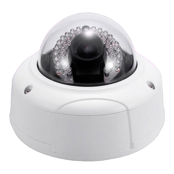
- Page 1 HD Vandal Proof IP Dome Camera User’s Manual Version 3.5.0...
- Page 2 Welcome Thank you for purchasing our IP camera! This user’s manual is designed to be a reference tool for your system. Please read the following safeguard and warnings carefully before you use this series product! Please keep this user’s manual well for future reference!
-
Page 3: Important Safeguards And Warnings
Important Safeguards and Warnings 1.Electrical safety All installation and operation here should conform to your local electrical safety codes. The power shall conform to the requirement in the SELV (Safety Extra Low Voltage) and the Limited power source is rated 12V DC or 24V AC in the IEC60950-1. We assume no liability or responsibility for all the fires or electrical shock caused by improper handling or installation. - Page 4 Always use the dry soft cloth to clean the device. If there is too much dust, please use the water to dilute the mild detergent first and then use it to clean the device. Finally use the dry cloth to clean the device.
-
Page 5: Table Of Contents
Table of Contents General Introduction ........................1 Overview ........................1 Features.........................1 Specifications ........................2 1.3.1 Performance......................2 1.3.2 Factory Default Setup ...................3 Structure ............................11 Multiple-function Combination Cable ..............11 Framework and Dimension..................12 Bidirectional talk ......................13 2.3.1 Device Connection ....................13 2.3.2 Operation ......................13 Alarm Setup.........................13 Installation ..........................15 Device Installation ......................15 SD Card Installation ....................18 Lens Adjustment......................18... - Page 6 FAQ ............................26 Appendix Toxic or Hazardous Materials or Elements ...............27...
-
Page 7: General Introduction
1 General Introduction 1.1 Overview This series IP camera integrates the traditional camera and network video technology. It adopts audio and video data collection, transmission together. It can connect to the network directly without any auxiliary device. This series IPC uses standard H.264 video compression technology and G.711a audio compression technology, which maximally guarantee the audio and video quality. -
Page 8: Specifications
Day/Night mode auto switch (ICR switch). Built-in IR light. Support IR night vision (For HDBW Series only). Backlight compensation: screen auto split to realize backlight compensation to adjust the bright. Support electronic shutter and gain setup. Support video watermark function to avoid vicious video modification. 1.3 Specifications 1.3.1 Performance Please refer to the following sheet for IPC performance specification. -
Page 9: Factory Default Setup
Privacy Mask Supports max 4 privacy mask zones Video Setup Support parameter setup such as bright, contrast. Video Channel title, time title, motion detect, privacy mask. Information Lens 3.3-12mm@F1.4 Lens Interface CS. Lens is the default accessories Audio Input 1-channel,RCA audio input. Audio Output 1-channel, RCA, audio output. - Page 10 Default setup Function Item Setup Type Series Brightness Contrast Saturation Exposure mode Auto Gain Scope 0~80 Auto Iris Profile Auto Day&Night Auto Backlight Mirror Flip No flip Flip 180° Video Bit stream General stream type Encode H.264B mode 1080P 720P(1280*72 Resolution (1920*1080)...
- Page 11 Default setup Function Item Setup Type Series Reference bit 192-1024Kb/S rate Bit rate 1024 I frame interval Snap type General snap 1080P 720P(1280*7 Image size (1920*1080) Snapshot Quality Better Interval Privacy mask Enable Overlay Channel title Enable Time title Enable Snapshot C:\PictureDownload Path...
- Page 12 Default setup Function IPVD-EL3MPIR Item Setup Type Series connection TCP port 37777 UDP port 37778 HTTP port Connection RTSP port HTTPs Disable Enable HTTPs port Enable Disable PPPoE User name Password Server type Disable ,CN99 DDNS Server IP none Port Domain none DDNS...
- Page 13 Default setup Function IPVD-EL3MPIR Item Setup Type Series SNMP v2 Disable SNMP port Read public community Write private community Trap address Trap port Enable Enable Bonjour “Device SN”. Server name Depends on the device. Multicast 239.255.42.42 address Multicast Port 36666 WIFI On(Enable) Enable...
- Page 14 Default setup Function IPVD-EL3MPIR Item Setup Type Series Snapshot Disable Enable Disable Relay input Alarm1 Anti-dither Sensor type Record Enable channel Record delay Alarm setup Relay (Alarm) Enable output Relay (Alarm) delay Send email Disable Snapshot Disable Relay (Alarm) output Abnormity Enable Disable...
- Page 15 Default setup Function IPVD-EL3MPIR Item Setup Type Series Record delay Enable Relay (Alarm) output Relay output delay Enable Disable Record Enable Record delay Relay (Alarm) Enable output Relay output delay FTP enable Disable Server IP Port User name anonymous Destination(Storag Password Remote share...
- Page 16 Default setup Function IPVD-EL3MPIR Item Setup Type Series DTS type Week 00:00:00 of the first Sunday of the Start time month 00:00:00 of the second Monday of End time the month Synchronize Disable with NTP NTP server clock.isc.org Port Update period Auto reboot Enable 02:00 each day...
-
Page 17: Structure
2 Structure 2.1 Multiple-function Combination Cable You can refer to the following figure for multiple-function combination cable information. See Figure 2-1 Figure 2-1 Please refer to the following sheet for detailed information. Port Name Function Connection Note Video output Output analog video signal. It can connect to the VIDEO OUT port TV monitor to view the video. -
Page 18: Framework And Dimension
Please refer to the follow sheet for detailed pin information. Port Name Name Note ALARM_COM Alarm output public port. Alarm output port. It is to output the alarm signal to the alarm device. ALARM_NO NO: normal open alarm output port. I/O Port Alarm input port 1. -
Page 19: Bidirectional Talk
Figure 2-3 2.3 Bidirectional talk 2.3.1 Device Connection Before the operation, connect the active pickup to the audio input port of the device. Connect the active speaker to the audio output port of the device. Please make sure the client-end device has the audio input and output function. - Page 20 Figure 2-4...
-
Page 21: Installation
3 Installation This series IPC can be put on the table to realize surveillance. Or you can use the bracket or the in- ceiling installation to realize the hang function. Please refer to the steps listed below. 3.1 Device Installation Step 1 Use the inner hexagonal wrench (provided) to loose the three inner hexagon screws in the dome cover and then open the cover. - Page 22 Step 3 Draw out the cable exit and four screw holes in the installation position according to the device pedestal. Dig the four plastic expansion bolt holes and cable exit. Insert the four plastic expansion bolts into the screw holes Step 4 Adjust the camera pedestal to the proper position and then draw the cable through the cable exit you just dug in the ceiling (wall).
- Page 23 e): Put the enclose back after you completed the setup. With IR light Without IR light Figure 3-4 Please note, the screws in the following figure are the optical adjustment component. Please make sure it is outward and do not allow it to touch the X-Y-Z axis module. See Figure 3-5 Figure 3-5 Step 7 Put the dome cover back and then put the three inner hexagon screws into the holes of the device.
-
Page 24: Sd Card Installation
3.2 SD Card Installation Important Before you install the SD card, please unplug he power cable to shut down the device! First, please refer to the step1 in the chapter 3.1 to open the device. Second, please adjust the proper position to install the SD card. Last, please refer to the step 7 in the chapter 3.1 to complete the installation. - Page 25 With IR light Without IR light Figure 3-8...
-
Page 26: Quick Configuration Tool
4 Quick Configuration Tool 4.1 Overview Quick configuration tool can search current IP address, modify IP address. At the same time, you can use it to upgrade the device. Please note the tool only applies to the IP addresses in the same segment. 4.2 Operation Double click the “ConfigTools.exe”icon, you can see an interface is shown as in Figure 4-1. - Page 27 Select the “Open Device Web” item; you can go to the corresponding web login interface. See Figure 4-3. Figure 4-3 If you want to modify the device IP address without logging in the device web interface, you can go to the configuration tool main interface to set.
- Page 28 Figure 4-5...
-
Page 29: Web Operation
5 Web Operation This series IPC product support the Web access and management via PC. Web includes several modules includes monitor channel preview, PTZ control, system configuration, alarm and etc. IP camera factory default setup: IP address: 192.168.1.108 or DHCP. User name: admin Password: admin 5.1 Network Connection... - Page 30 Figure 5-2 If it is your first time to login in, system pops up warning information to ask you whether install control webrec.cab or not after you logged in for one minute. Please click OK button, system can automatically install the control. When system is upgrading, it can overwrite the previous Web too. If you can’t download the ActiveX file, please check whether you have installed the plug-in to disable the control download.
- Page 31 Figure 5-4 Please refer to the Web Operation Manual included in the resource CD for detailed operation instruction.
- Page 32 6 FAQ I can not boot up Please click RESET button for at least five seconds to restore the device. factory default setup. card write Do not set the SD card as the storage media to storage the times schedule record file. It may damage the SD card duration. I can not use the When disk information is shown as hibernation or capacity is 0, disk as the storage...
-
Page 33: Appendix Toxic Or Hazardous Materials Or Elements
Appendix Toxic or Hazardous Materials or Elements Toxic or Hazardous Materials or Elements Component Name Cr VI PBDE Circuit Board ○ ○ ○ ○ ○ ○ Component Device Construction ○ ○ ○ ○ ○ ○ Material Wire and Cable ○ ○...
Need help?
Do you have a question about the IPVD-EL3MPIR Series and is the answer not in the manual?
Questions and answers