Table of Contents
Advertisement
Quick Links
Advertisement
Table of Contents

Related Manuals for Security Camera King IPOD-EL1MPIR50-E


Summary of Contents for Security Camera King IPOD-EL1MPIR50-E
- Page 1 IPOD-EL1MPIR50-E User’s Manual Version 1.3.0...
- Page 2 Welcome Thank you for purchasing our Network camera! This user’s manual is designed to be a reference tool for your system. Please read the following safeguard and warnings carefully before you use this series product! Please keep this user’s manual well for future reference!
- Page 3 Important Safeguards and Warnings 1.Electrical safety All installation and operation here should conform to your local electrical safety codes. The power shall conform to the requirement in the SELV (Safety Extra Low Voltage) and the Limited power source is rated 12V DC or 24V AC in the IEC60950-1. (Refer to general introduction) Please note: Do not connect two power supplying sources to the device at the same time;...
- Page 4 Do not touch the CCD (CMOS) optic component. You can use the blower to clean the dust on the lens surface. Always use the dry soft cloth to clean the device. If there is too much dust, please use the water to dilute the mild detergent first and then use it to clean the device.
-
Page 5: Table Of Contents
Table of Contents General Introduction ......................1 Overview ........................1 Features ........................1 Specifications ......................2 Structure ..........................9 Components ......................9 Framework and Dimension ................... 10 Device Installation ....................... 13 Installation Steps for Metal Dome................. 13 Installation Steps for Plastic Dome ............... 14 Quick Configuration Tool .................... -
Page 6: General Introduction
1 General Introduction 1.1 Overview This series network camera integrates the traditional camera and network video technology. It adopts video data collection, transmission together. It can connect to the network directly without any auxiliary device. This series network camera uses standard H.264 video compression technology, which maximally guarantees the video quality. -
Page 7: Specifications
1.3 Specifications Please refer to the following sheet for network camera performance specification. IPOD-EL1MPIR Model IPC- 50-E Parameter Main Processor High performance DSP Embedded LINUX System Support real-time network, local record, and remote operation at the Resources same time. User Interface Remote operation interface such as WEB, DSS, PSS System Status Bit stream statistics, log, and software version. - Page 8 Wire Network 1-ch 10/100 Base-T Ethernet HTTP, TCP/IP, ARP,IGMP, ICMP, RTSP, RTP,UDP, RTCP, SMTP, Network Protocol FTP, DHCP, DNS, DDNS, PPPOE, UPNP, NTP Remote Monitor, system setup, file download, log information, maintenance , Operation upgrade and etc IR light IR light 20M. Power DC12V power and PoE.
- Page 9 Video Setup Support parameter setup such as bright, contrast. Video Channel title, time title, motion detect, camera masking. Information Lens 2.8mm, 3.6mm, 6mm. Fixed focus. Lens Interface M12. Lens is the default accessories 396 (18*22) detection zones; sensitivity level ranges from 0 to 100; area threshold ranges from 0 to 100.
- Page 10 PAL: Main stream (1280*960@25fps), Video Frame extra stream ( 704*576@25fps) Rate NTSC: Main stream (1280*960@30fps), extra stream ( 704*480@30fps) H.264H: 16Kbps-8192Kbps Video Bit Rate MJPEG: adjustable and bit rate is adjustable. Support customized setup. Support mirror. Video Flip Support flip function. Snapshot Max 1f/s snapshot.
- Page 11 User Interface Remote operation interface such as WEB, DSS, PSS System Status Bit stream statistics, log, and software version. Image Sensor 1/3-inch CMOS Pixel 1280(H)*960(V) 2048(H)*1536(V) Day/night Support day/night mode switch Gain Control Fixed/Auto White Balance Manual/Auto On/Off Manual/Auto/Low noise/Low motion blur Exposure Mode It ranges from 1/3 to 1/100000.
- Page 12 Consumption Working -30℃~+60℃ Temperature Working ≤95% Humidify Φ113.6×85.8 Dimensions(mm) Weight 0.27kg Installation Ceiling and wall mount Model Parameter Main Processor High performance DSP Embedded LINUX System Support real-time network, local record, and remote operation at the Resources same time. User Interface Remote operation interface such as WEB, DSS, PSS System Status Bit stream statistics, log, and software version.
- Page 13 396 (18*22) detection zones; sensitivity level ranges from 0 to 100; area threshold ranges from 0 to 100. Motion Detect Activation event: video storage, image snapshot, log, email function and etc. Record Priority Manual >Video detect>Schedule Wire Network 1-ch 10/100M Ethernet, RJ45 port HTTP, TCP/IP, ARP,IGMP, ICMP, RTSP, RTP,UDP, RTCP, SMTP, Network Protocol FTP, DHCP, DNS, DDNS, PPPOE, UPNP, NTP...
-
Page 14: Structure
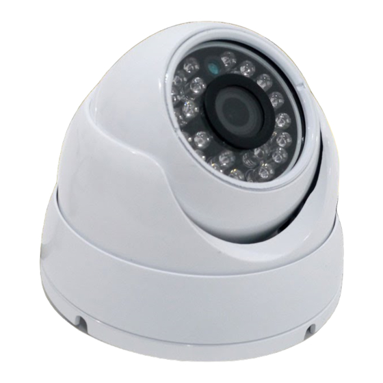
2 Structure 2.1 Components You can refer to the following figures for product appearance information. See Figure 2-1 and Figure Figure 2-1 Metal Dome Figure 2-2 Plastic Dome... -
Page 15: Framework And Dimension
Please refer to the following sheet for detailed information. Component Component Name Component 1 Device lens Component 2 Dome body Component 3 Dome enclosure Port Name Connector Note connect standard Ethernet. Note: Some devices Network Ethernet support PoE. port ... - Page 16 Figure 2-4 Dimension of Metal Dome 2 Figure 2-5 Dimension of Plastic Dome 1...
- Page 17 Figure 2-6 Dimension of Plastic Dome 2...
-
Page 18: Device Installation
3 Device Installation Important Before the installation, please make sure the installation environments can at least support 3x weight of the camera. 3.1 Installation Steps for Metal Dome Please follow the steps listed below to install the device. Please refer to Figure 3-1 to Figure 3-3 for reference. -
Page 19: Installation Steps For Plastic Dome
Please pay attention to the dome camera direction when you are installing. Please refer to the following figure for detailed information. See Figure 3-2. Figure 3-2 Device installation illustration 2 Figure 3-3 Device installation illustration 3 3.2 Installation Steps for Plastic Dome Please follow the steps listed below to install the device. - Page 20 Figure 3-4 Device installation illustration 1 Step 1 Rotate decoration ring clockwise and take it out. Step 2 Take out installation map in accessories bag, and according to monitoring area, paste it on ceiling or wall there device will be installed. Dig three hole at the position marked on installation map, and take out three expansion bolts in accessories bag to insert them into the holes.
-
Page 21: Quick Configuration Tool
4 Quick Configuration Tool 4.1 Overview Quick configuration tool can search current IP address, modify IP address. At the same time, you can use it to upgrade the device. Please note the tool only applies to the IP addresses in the same segment. 4.2 Operation Double click the “ConfigTools.exe”... - Page 22 In the configuration tool search interface (Figure 4-1), please select a device IP address and then double click it to open the login interface. Or you can select an IP address and then click the Login button to go to the login interface. See Figure 4-3. In Figure 4-3, you can view device IP address, user name, password and port.
-
Page 23: Web Operation
5 Web Operation This series network camera products support the Web access and management via PC. Web includes several modules: Monitor channel preview, system configuration, alarm and etc. 5.1 Network Connection Please follow the steps listed below for network connection. ... - Page 24 Figure 5- 2 Web login After you successfully logged in, please install WEB plug-in unit. Please refer to the Web Operation Manual included in the resource CD for detailed operation instruction. See Figure 5- 3. Figure 5- 3 Web monitoring window...
-
Page 25: Faq
6 FAQ The water leakage The unauthorized front or rear cap remove many result in water occurred. leakage. The glass front cap has sustained heavy push or strike. The waterproof plug of the rear cap becomes loosen. IR video is poor. Do not use the proper supplying power. -
Page 26: Appendix Toxic Or Hazardous Materials Or Elements
Appendix Toxic or Hazardous Materials or Elements Toxic or Hazardous Materials or Elements Component Name Cr VI PBDE Circuit Board ○ ○ ○ ○ ○ ○ Component ○ ○ ○ ○ ○ ○ Device Case ○ ○ ○ ○ ○ ○...
Need help?
Do you have a question about the IPOD-EL1MPIR50-E and is the answer not in the manual?
Questions and answers