Advertisement
Quick Links
Advertisement

Summary of Contents for Security Camera King IPOB-ELS2IR12XA-EP
-
Page 2: Important Safeguards And Warnings
Important Safeguards and warnings 1.Electrical Safety all installation and operation here should conform to your local electri- cal safety codes. The power shall conform to the requirement in the SELV(Safety Extra Low Voltage) and the Limited power source is rated 12V DC (24V AC) in the IEC60950-1. - Page 3 Important Safeguards and Warnings This series camera be used in the specified working tem- perature. Please keep it away from electromagnetic radia- tion objects and environments. Please keep the sound ventilation. Do not allow water and other liquid from falling into the camera.
-
Page 4: General Introduction
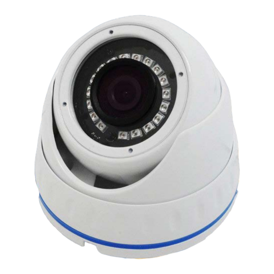
General Introduction 1.1 Overview This series megapixel HD camera conforms to the HDCVI standard. It sup- ports video signal high-speed long distance transmission without any delay. It can be controlled by the DVR conforming to the HDCVI. 1.2 Features • High-performance CMOS image sensor, megapixel definition. - Page 5 Dome Framework and Dimensions Please refer to the following figures for Dimension infor- mation. The unit is mm(millimeter). Important Dimensions of Cameras may vary depending on your model. If you are having trouble finding the dimensions you can find the measurements by using a caliper or try your best using a ruler.
- Page 6 HD-CVI Plastic Housing Lens Dome Body Decoration Ring...
- Page 7 HD-CVI Glass Housing Dome Cover Dome Enclosure IR Light Dome Module Dome Pedestal Power Input Port Video Output Port SD/HD Switch Cable...
-
Page 8: Dome Installation
When the Standard definition/high definition switch control cable is short circuit, systems outputs standard definition video. Otherwise, when the cir- cuit is open, system outputs the high definition video. Dome Installation Important Before the installation, please make sure the installation surface can sustain at least 3X weight of the bracket and the camera. - Page 9 Step 1 Take the installation position map from the accessories bag and them put it on the surface of the ceiling or the wall according to the cable exit position. Dig three holes according to the installation position map and then take three ex- pansion bolts from the accessories bag and put them to the holes you just dug.
- Page 10 HDCVI Plastic Housing Step 1 Please take the installation position map in the accessories bag, and then paste it on the ceiling or the wall according to your monitor area require- ments. Draw and then dig three holes in the installation surface and then insert three expansion bolts in the holes.
- Page 11 Step 3 Adjust the lens to get the clear monitor video. Use cross-head screwdriver to loosen the screw and then turn the camera body to the proper position man- ually. Fix the screw again. Important Do not remove the screw. Loosen a little bit. Please secure after you have completed the setup.
- Page 12 HDCVI Metal Housing Step 1 Device Installation Take the wrench from the accessories bag and use it to loosen the three set of screws on the side of the camera body. Step 2 Pedestal installation Turn the pedestal of the device and then pull the cable through it. Use four screws to secure the pedestal to the proper position.
- Page 13 Pedestal 1 Step 3 Adjust Monitor Angle Turn the pan base to the pedestal and secure firmly. Adjust rotate base and the dome body to get the lens to the proper monitor angle. B1 Pedestal B2 Pan Base B3 Rotate Base B4 Dome Body Step 4 Fix Monitor Angle To prevent the dome from moving, use wrench to secure the three set...
- Page 14 Bullet Framework Dimensions Please refer to the following figures for Dimension infor- mation. The unit is mm(millimeter). Important Dimensions of Cameras may vary depending on your model. If you are having trouble finding the dimensions you can find the measurements by using a caliper or try your best using a ruler.
- Page 15 Bullet Installation Important Before the installation, please make sure the installation surface can sustain at least 3X weight of the bracket and the camera. 2 Megapixel Camera Before you install the bracket, please pull the cable through the cable exit of the bracket chassis.
- Page 16 Step 2 Unscrew the M3 x 20 and M3 x 5 screws on the bracket and adjust the camera via the three directions indicated in the figure below have the cam- era facing the exact location which needs to be monitored by rotating the bracket and camera body, then secure the bolts.
- Page 17 Menu HDCVI Series DVR settings The following operation and interfaces for reference only. Please refer to the HDCVI series DVR user’s manual for detailed information. After connecting the camera to the HDCVI series DVR, from Main Menu ->Setting->System->PTZ, you need to set control mode as HDCVI and the protocol as DH-SD1.
- Page 18 On the preview interface, right click mouse and then select PTZ; you can see an interface shown as below. Click Iris “+” to open menu or confirm current operation. Click up/down button to view all the items on the left pane of the following list. Click left/ right button to set the corresponding values on the right pane of the follow- ing list.


Need help?
Do you have a question about the IPOB-ELS2IR12XA-EP and is the answer not in the manual?
Questions and answers