Marantz SR5500 User Manual
Marantz av surround receiver user guide sr5500u
Hide thumbs
Also See for SR5500:
- Service manual (100 pages) ,
- User manual (42 pages) ,
- Full line catalog (36 pages)

Related Manuals for Marantz SR5500


Summary of Contents for Marantz SR5500
- Page 1 Model SR5500 User Guide AV Surround Receiver SR5500U DFU_00_cover Page 7 04.8.2, 3:26 PM Adobe PageMaker 6.5J/PPC...
-
Page 2: Important Safety Instructions
CAUTION RISK OF ELECTRIC SHOCK DO NOT OPEN CAUTION: TO REDUCE THE RISK OF ELECTRIC SHOCK, DO NOT REMOVE COVER (OR BACK) NO USER-SERVICEABLE PARTS INSIDE REFER SERVICING TO QUALIFIED SERVICE PERSONNEL The lightning flash with arrowhead symbol within an equilateral triangle is intended to alert the user to the presence of uninsulated “dangerous voltage”... - Page 3 Grounding or Polarization – This product may Lightning – For added protection for this be equipped with a polarized alternating- product during a lightning storm, or when it is current line plug (a plug having one blade left unattended and unused for long periods of wider than the other).
-
Page 4: Table Of Contents
PROGRAMMING THE REMOTE CONTROLLER ... 8 ATTENUATION TO ANALOG INPUT SIGNAL ... 27 OPERATION OF REMOTE CONTROL UNIT ... 9 LISTENING THROUGH HEADPHONES ... 27 GENERAL INFORMATION OF RC5500SR TO SR5500 .. 9 DOLBY HEADPHONE MODE ... 27 CONNECTIONS ... 11 VIDEO ON/OFF ... 27 SPEAKER PLACEMENT ... -
Page 5: Description
DESCRIPTION DTS-ES Extended Surround is a new multichannel digital signal format developed by Digital Theater Systems Inc. While offering high compatibility with DTS was introduced in 1994 to provide 5.1 channels the conventional DTS Digital Surround format, of discrete digital audio into home theater systems. DTS-ES Extended Surround greatly improves the D T S b r i n g s y o u p r e m i u m q u a l i t y d i s c r e t e 360-degree surround impression and space... -
Page 6: Features
Music), Dolby Pro-Logic IIx (Movie, Music and octave. Game), Circle Surround II (Cinema and Music) . In addition, Marantz has focused on the future. By Circle Surround II, Dialog Clarity, TruBass, SRS utilizing pre-out jacks, 7.1 direct inputs and a RS-... -
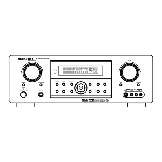
Page 7: Front Panel
HEADPHONE jack for stereo headphones This jack may be used to listen to the SR5500’s output through a pair of headphones. Be certain that the headphones have a standard 1 / 4” stereo phono plug. -
Page 8: Fl Display
SPKR B ¡8 ¡7 DISP (Display Off) indicator V (video)-OFF mode indicator This indicator is illuminated when the SR5500 is in This indicator is illuminated when the Video-OFF the display off condition. function is active. SLEEP timer indicator NIGHT mode indicator... -
Page 9: Rear Panel
Use these jacks for connection to external power amplifiers. Power cable AC IN Connect to an AC power outlet. SR5500 has to be powered by 120 V AC only. AC OUTLETS SWITCHED UNSWITCHED 1A 120W MAX 1A 120W MAX AC OUTLETS Connect the AC power cables of components such as a DVD and CD player to these outlets. -
Page 10: Remote Control Operation
(Main) POWER buttons FUNCTION AND OPERATION (when AMP mode is selected) Press to switch the power of the SR5500 ON or OFF The provided remote control unit is a universal after pressing the AMP button. remote controller. The POWER button, numeric buttons and control buttons are used in common across different input source components. -
Page 11: Programming The Remote Controller
¤1 PURE DIRECT button PROGRAMMING THE REMOTE When this button is pressed, the tone control CONTROLLER circuit is bypassed. The remote controller RC5500SR must be programmed to use the codes for your appliances ¤2 SETUP / T.TONE button of different brands. This is done by keying in a 4- digit code or by scanning the codes until the (when AMP mode is selected) correct one is found. -
Page 12: Operation Of Remote Control Unit
Page 9 GENERAL INFORMATION OF RC5500SR TO SR5500 To control the SR5500 by your RC5500SR, you have to select the device AMP or TUNER by pressing the function selector button. Please refer below for the details in AMP and TUNER mode. - Page 13 THE CONTRABLE FUNCTION TABLE POWER POWER POWER POWER POWER VCR1 DSS/VCR2 CALL UP CALL UP CALL UP MENU TUNER TAPE CDR/MD MENU MENU AUX1 Cursor Cursor Cursor MAIN VOL. SLEEP MUTE VOL. ENTER MENU SETUP SETUP/T.TONE – – ENTER CANCEL SET UP/ MENU OFF MENU OFF...
-
Page 14: Connections
Surround left and right speakers CONNECTIONS When the SR5500 is used in surround operation, the preferred location for surround speakers is on the side walls of the room, at or slightly behind the listening position. SPEAKER PLACEMENT The center of the speaker should face into the The ideal surround speaker system for this unit is room. -
Page 15: Connecting Audio Components
Caution: CONNECTING AUDIO COMPONENTS • Be sure to use speakers with the specified impedance as shown on the rear panel of this unit. • To prevent damage to circuitry, do not let the bare CD RECORDER / MD DECK s p e a k e r w i r e s touch each other and do not let them touch any metal... -
Page 16: Connecting Video Components
Use a component video cable or 3 video cords to connect the component video out jacks on the SR5500 to the monitor. Notes: • Be sure to connect the left and right audio channels properly. -
Page 17: Advanced Connecting
Therefore you need to aim the remote signal only to the unit. Also, if a Marantz power amplifier (some models excluded) is connected to one of these terminals, the power amplifier’s, power switch is synchronized with this... -
Page 18: Connecting The Antenna Terminals
ANTENNA FM ANTENNA ANTENNA ANTENNA COMPONENT VIDEO INPUT-1 INPUT-2 MONITOR OUT FM (75Ω) FM (75Ω) VIDEO S-VIDEO VCR1 DSS/VCR2 MONITOR MODEL NO. SR5500 VCR1 DSS/VCR2 MONITOR MULTI DIGITAL IN DIGITAL OUT RC-5 COAX. RS-232C OPT. VCR1 DSS/VCR2 TAPE CDR/MD MULTI 7.1CH... -
Page 19: Connecting For The Multi Room
CONNECTING FOR THE MULTI ROOM ANTENNA COMPONENT VIDEO INPUT-1 INPUT-2 MONITOR OUT FM (75Ω) VIDEO S-VIDEO VCR1 DSS/VCR2 MODEL NO. SR5500 VCR1 DSS/VCR2 MONITOR MONITOR MULTI MULTI RC-5 DIGITAL IN DIGITAL OUT COAX. RS-232C OPT. VCR1 DSS/VCR2 TAPE CDR/MD MULTI MULTI 7.1CH... -
Page 20: Setup
After all components are connected, initial setup must be performed. ON SCREEN DISPLAY MENU SYSTEM The SR5500 incorporates an on-screen menu system, which makes various operations possible by using the cursor ( , ) and ENTER buttons on the remote control or on the front panel. -
Page 21: Input Setup (Assignable Digital Input And Component Video Input)
1 INPUT SETUP (ASSIGNABLE DIGITAL 2 SPEAKER SETUP INPUT AND COMPONENT VIDEO INPUT) After you have installed the SR5500, connected all the components, and determined the speaker 4 digital inputs and 2 component video inputs can layout, it is now time to perform the settings in the be assigned to a desired source. -
Page 22: Preference
-10 and +10 dB in 1 dB intervals except the subwoofer setting. The subwoofer can be adjusted to any level between -15 and +10 dB in 1 dB intervals.) The SR5500 will now emit the pink noise from the center speaker. Using the cursor buttons, adjust the... -
Page 23: Surround
CDs. L F E L E V E L 0 d B In this mode, SR5500 includes three controls to fine-tune the soundfield as follows. 5 P L II MU S I C P ARAME T E R... -
Page 24: 7.1 Ch Input Level
LEVEL (VOLUME LEVEL): 8 7.1 CH INPUT LEVEL Adjust the Multi-speaker output level with cursor button. This sub-menu is to adjust the speaker levels for 7.1-channel input sources. Note: Here you will adjust the volume for each channel so • This setting can be changed when the Surr Back is that they are all heard by the listener at the same set “NONE”... -
Page 25: Simple Setup
Press the SIMPLE SETUP button on the unit to enter this menu. 6.1 ch LARGE 1. 2. 4. 3. 5. 6.0 ch LARGE 5.1 ch LARGE AV SURROUND RECEIVER SR5500 INPUT SELECTOR VOLUME 5.0 ch LARGE SURROUND DISP MULTI AUTO TUNED V –... -
Page 26: Basic Operation (Play Back)
Example: front-panel. Monitor is connected with the component. • As the input is changed, the SR5500 will automatically switch to the digital input, surround mode, attenuation, and night mode s t a t u s w h i c h w e r e e n t e r e d d u r i n g t h e configuration process for that source. -
Page 27: Temporarily Turning Off The Sound
MUTE VOL. MENU ENTER To program the SR5500 for automatic standby, press the SLEEP button on the remote. Each press of the button will increase the time before shut down in the following sequence. The sleep time will be shown for a few seconds in the display on the front panel, and it will count down until the time has elapsed. -
Page 28: Pure-Direct
Dolby Digital, Dolby Pro signals from certain CD players and LD players Logic or DTS. even if you connect the player to the SR5500 digitally. This is because the digital signal has STEREO been processed (such as the output level, sampling frequency, or frequency response) This mode bypasses all surround processing. - Page 29 The surround mode is selected with the surround AUTO mode selector on SR5500 or the remote control unit. However, the sound you hear is subject to the relationship between the selected surround mode and input signal. That relationship is as follows;...
-
Page 30: Other Function
OFF or select a channel that does not contain LISTENING THROUGH HEADPHONES any broadcast. This jack may be used to listen to the SR5500’s The power to the SR5500 switches to output through a pair of headphones. Be certain STANDBY after approx. 5 minutes. -
Page 31: Selecting Analog Audio Input Or Digital Audio Input
SELECTING ANALOG AUDIO INPUT RECORDING AN ANALOG SOURCE OR DIGITAL AUDIO INPUT In normal operation, the audio or video source selected for listening through the SR5500 is sent to the record outputs. TUNER TAPE CDR/MD This means that any program you are watching or... -
Page 32: Aux2 Input
The LIP.SYNC feature delays the Notes: audio signal with respect to the image signal output from the SR5500 to correct the time lag • When the 7.1 CH. Input is in use, you may not between the sound and image. It can be operated select a surround mode, as the external decoder with the “LIP.SYNC”... -
Page 33: Preset Memory
(Using the SR5500) 2. 4. 2. 5. 1. 3. Tune into the radio station you desire (Refer to the “MANUAL TUNING” or “AUTO TUNING” AV SURROUND RECEIVER SR5500 INPUT SELECTOR VOLUME section). DISP MULTI AUTO TUNED V –... -
Page 34: Sorting Preset Stations
CLEARING STORED PRESET STATIONS SORTING PRESET STATIONS You can remove preset stations from the memory using the following procedure. AV SURROUND RECEIVER SR5500 INPUT SELECTOR 2. 3. SET UP/ MENU OFF T.TONE PURE DIRECT AUTO NIGHT CSII EX/ES VIRTUAL MULTI M. -
Page 35: Multi Room System
A separately sold stereo power amplifier can be you to listen to the same or a different source in a connected to enjoy multi room playback. room other than the room in which the SR5500 is The MULTI OUT system can not be operated with located. -
Page 36: Troubleshooting
If your trouble cannot be recovered with the remedy actions listed in the following table, malfunction of the internal circuitry is suspected; immediately unplug the power cable and contact your dealer, nearest Marantz authorized dealer or the Marantz Service Center in your country. SYMPTOM CAUSE SR5500 cannot be turned up. -
Page 37: Technical Specifications
Input Sensitivity/Impedance ... 168 mV/ 47 Kohms reset the unit with the following procedure. Signal to Noise Ratio(Analog Input / Source Direct) ... 105 dB The SR5500 is turned on, press and hold the Frequency Response MULTI and 7.1CH INPUT buttons simultaneously (Analog Input / Source Direct) for 3 seconds or more. -
Page 38: Setup Codes
Luxman ... 0120 JVC ... 0321 LXI ... 0332 Kenwood ... 0999 Magnavox ... 0184, 0332 Marantz ... 0999 Marantz ... 0999, 0056, 0184 Philips ... 0999 MCS ... 0056 Pioneer ... 0089, 0114 Miro ... 0027 Sony ... 0391, 0127 Mission ... - Page 39 LXI ... 0074, 0081, 0181, 0183, 0205 Soundesign ... 0207, 0205 Magnavox ... 0081, 0057, 1481, 0733, 1281 Squareview ... 0198 Marantz ... 0081, 0057, 1581, 0731 SSS ... 0207 Matsushita ... 0277, 0677 Starlite ... 0207 Megatron ... 0205, 0172 Studio Experience ...
- Page 40 STS ... 0069 Koss ... 0678 Sylvania ... 0062, 0108, 0027, 0070, 1808 Magnavox ... 0530, 0848 Symphonic ... 0027 Marantz ... 0566 Teac ... 0027 Memorex ... 0722 Technics ... 0062, 0189 Microsoft ... 0549 Teknika ... 0062, 0064, 0027 Mintek ...
- Page 41 You can find your nearest authorized distributor or dealer on our website. JAPAN Marantz Japan, Inc. 35-1 Sagami Ohno 7-Chome, Sagamihara-shi, Kanagawa 228-8505, Japan U.S.A. Marantz America, Inc. 1100 Maplewood Drive, Itasca, IL 60143, U.S.A. EUROPE Marantz Europe B.V.
Need help?
Do you have a question about the SR5500 and is the answer not in the manual?
Questions and answers