
Related Manuals for Champion Power Equipment CSA40017


Summary of Contents for Champion Power Equipment CSA40017
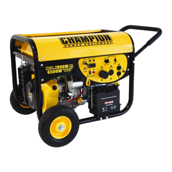
- Page 1 CSA40017 Rev CSA40017-20070612 10006 Santa Fe Springs Road Santa Fe Springs, CA 90670 USA Made in China Owner’s Manual and Operating Instructions 7800 Peak Watts/6500 Running Watts PORTABLE GENERATOR...
-
Page 3: Table Of Contents
Table of Contents Introduction ........1 Storage ........... 14 Portable Power Generator ......1 Engine Storage ........14 Accessories..........1 Generator Storage........14 This Booklet ..........1 Specifications ......... 15 Manual Conventions ......2 Engine Specifications......15 Safety Rules ........3 Generator Specifications......15 Controls and Features....... -
Page 5: Introduction
Champion Power Equipment manufactures Congratulations on your purchase of a and sells accessories designed to help you Champion Power Equipment generator. CPE get the most from your purchase. To find out designs and builds generators to strict more about our covers, power cables and specifications. -
Page 6: Manual Conventions
NOTE If you have questions regarding your generator, WARNING we can help. Please call our help line at 1-877- 338-0999. WARNING indicates a potentially hazardous could situation which, if not avoided, result in death or serious injury. Rev CSA40017-20070612... -
Page 7: Safety Rules
Traumatic amputation or severe laceration can result. Keep hands and feet away from rotating parts. Tie up long hair and remove jewelry. Operate equipment with guards in place. DO NOT wear loose-fitting clothing, dangling drawstrings or items that could become caught. Rev CSA40017-20070612... - Page 8 DO NOT allow any material to block the cooling slots. If connected devices overheat, turn them off and disconnect them from the generator. DO NOT use the generator if: Electrical output is lost Equipment sparks, smokes or emits flames Equipment vibrates excessively Rev CSA40017-20070612...
-
Page 9: Controls And Features
Air Cleaner (4) – Protects the engine by Oil Filler Cap (8) – Check and fill engine filtering dust and debris from the intake air. oil level. Recoil Starter (5) – Used to start the Power Panel (9) – See “Power Panel” engine Rev CSA40017-20070612... -
Page 10: Power Panel
60 Hz loads requiring up to 20 A 0r 2400 Panel Light (7) – Switch for the control Watts of power. panel LED lighting. Ground Terminal (12) – Consult an Parameter Button (8) – Push-button electrician for local grounding regulations. selector for the Intelligauge Rev CSA40017-20070612... -
Page 11: Parts Included
Controls and Features Parts Included Your CSA40017 Gasoline Powered Generator ships with the following parts: Wheel Kit Axle 1 piece 10” Solid Wheel 2 pieces Support Leg 1 piece Vibration Mounts 2 pieces Bolt Kit Wheel Retaining Pins 2 pieces... -
Page 12: Assembly
6. Carefully bend the legs of the cotter pin 4. Check engine oil level daily and add as back around the axle. needed. 7. Repeat steps 3-6 to attach the second wheel. Rev CSA40017-20070612... -
Page 13: Add Fuel
DO NOT fill fuel tank indoors. DO NOT fill fuel tank when the engine is running or hot. DO NOT overfill the fuel tank. DO NOT light cigarettes or smoke when filling the fuel tank. Rev CSA40017-20070612... -
Page 14: Operation
DO NOT connect 50 Hz loads to the your sensitive equipment. generator. Surge suppressors come in single- or DO NOT overload the generator. multi-outlet styles. They’re designed to protect against virtually all short- duration voltage fluctuations. Rev CSA40017-20070612... -
Page 15: Stopping The Engine
4. Allow the engine to stabilize. Hand Drill 1/2" 1000 1000 5. Plug in and turn on the next item. Paint Sprayer 1200 6. Allow the engine to stabilize. Table Saw 2000 2000 7. Repeat steps 5-6 for each additional item. Rev CSA40017-20070612... -
Page 16: Maintenance
Remove the oil drain plug with a 15 mm socket and extension. 2. Allow the oil to drain completely. 3. Replace the drain plug. 4. Remove oil fill cap/dipstick to add oil. 5. Add 1.16 qt (1.1 L) of oil and replace oil fill cap/dipstick. Rev CSA40017-20070612... -
Page 17: Spark Arrester (If Installed)
Contact our help line at 1-877-338-0999 to Inspect all air vents and cooling slots to locate the nearest Champion Power ensure that they are clean and unobstructed. Equipment certified service dealer for your generator or engine maintenance needs. Rev CSA40017-20070612... -
Page 18: Storage
Maintenance section. 5. Store in a clean, dry place out of direct 3. Drain all fuel completely from the fuel sunlight. line and carburetor to prevent gum from forming. 4. Add a fuel stabilizer into the fuel tank. Rev CSA40017-20070612... -
Page 19: Specifications
Intake 0.13-0.17mm (0.005 – 0.007 in.) Fuel Exhaust 0.18-0.22mm (0.007 – 0.009 in.) Fuel capacity is 6.5 US gallons (25 L). Use regular unleaded gasoline with a minimum octane rating of 85. Oil capacity is 1.16 qt (1.1 L). Rev CSA40017-20070612... -
Page 20: Parts Diagram
Specifications Parts Diagram Rev CSA40017-20070612... -
Page 21: Parts List
Big Washer ø8 GB93-LW-8 Spring washer φ8 GB5781-B8-35 Bolt M8×35 ST05FD-1151300A Motor Mount A ST05FD-1151300B Motor Mount B GB41-N-8 Nut M8 ST188FD-1744001-K Axle GB41-N-10 Nut M10 ST188FD-1742100-UC Frame ST160F-1070001-1 Hose Clamp ST188FD-1160002 Fuel Line ST168FD-1160400 Fuel Cock ST05FD-04190000 Fuel Tank Rev CSA40017-20070612... - Page 22 Bushing ø8.5 ST188FD-1732101 Muffler Inner protector ST02FD-1152036 Brush Support Plate ST182FD-1742203-UC Handle Sheath ST182FD-1742201-UC Handle ST182FD-1742202-UC Handle Underlay GB896-86-1 Baffle Clip I GB896-86-2 Baffle Clip II ST182FD-1742002-UC ST02FD-1151207-M Grounding Wire GB5781-B8-32 Bolt M8×32 ST188FD-1740004-C Vibration Mount ST188FD-1743001-T Support leg Rev CSA40017-20070612...
- Page 23 Fuel Tank Wing ST188FD-1740100-D Wheel GB90-W-16 Washer ø16 GBT-CP3.2-40 Cotter Pin 3.2×40 ST188FD-1750002-C1 Red Battery Wire ST188FD-1750002-C2 Black Battery Wire ST188FD-1751002 Jacket GB41-N-6 Nut M6 ST188FD-1700210-C Battery setting plate FM12180 Battery ST188FD-1700203-C Bolt ST188FD-1700200-C Battery Guard GB5781-B8-50 Bolt M8×50 Rev CSA40017-20070612...
-
Page 24: Wiring Diagram
Wiring Diagram Wiring Diagram... -
Page 25: Troubleshooting
Contact the help line. Generator gallops Engine governor defective Contact the help line Repeated circuit breaker tripping Overload Review load and adjust. See “Power Management” Faulty cords or device Check for damaged, bare or frayed wires. Replace defective device Rev CSA40017-20070612... -
Page 26: Warranty
Wear items such as filter elements, o-rings, etc. Warranty Qualifications Accessory parts such as starting batteries, and Champion Power Equipment (CPE) will register storage covers. Failures to due acts of God and other force this warranty upon receipt of your Warranty Registration Card and a copy of your sales receipt majeure events beyond the manufacturer’s... -
Page 27: Notes
Notes Notes Rev CSA40017-20070612...
Need help?
Do you have a question about the CSA40017 and is the answer not in the manual?
Questions and answers