Table of Contents
Advertisement
Quick Links
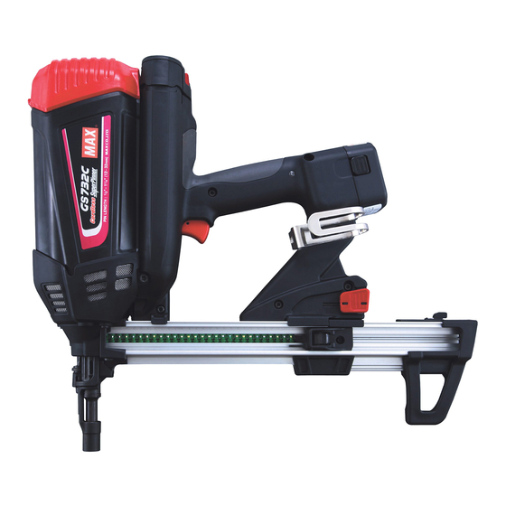
GS732C LT
MAX CORDLESS FASTENING SYSTEM
SYSTÈME DE FIXATION SANS CORDON MAX
SISTEMA DE FIJACIÓN SIN CORDÓN MAX
OPERATING AND MAINTENANCE MANUAL
MANUEL D'UTILISATION ET D'ENTRETIEN
MANUAL DE OPERACIONES Y MANTENIMIENTO
BEFORE USING THIS TOOL, STUDY THIS MANUAL TO ENSURE SAFETY WARNING AND IN-
STRUCTIONS.
KEEP THESE INSTRUCTIONS WITH THE TOOL FOR FUTURE REFERENCE.
WARNING
AVANT D'UTILISER CET OUTIL, LIRE CE MANUEL ET LES CONSIGNES DE SÉCURITÉ AFIN DE
GARANTIR UN FONCTIONNEMENT SÛR.
CONSERVER CE MANUEL EN LIEU SÛR AVEC L'OUTIL AFIN DE POUVOIR LE CONSULTER UL-
TÉRIEUREMENT.
AVERTISSEMENT
ANTES DE UTILIZAR ESTA HERRAMIENTA, LEA DETENIDAMENTE ESTE MANUAL PARA FAMILIARIZARSE CON
LAS ADVERTENCIAS E INSTRUCCIONES DE SEGURIDAD.
CONSERVE ESTAS INSTRUCCIONES JUNTO CON LA HERRAMIENTA PARA FUTURAS CONSULTAS.
ADVERTENCIA
Advertisement
Table of Contents

Related Manuals for Max GS732C LT


Summary of Contents for Max GS732C LT
- Page 1 GS732C LT MAX CORDLESS FASTENING SYSTEM SYSTÈME DE FIXATION SANS CORDON MAX SISTEMA DE FIJACIÓN SIN CORDÓN MAX OPERATING AND MAINTENANCE MANUAL MANUEL D'UTILISATION ET D'ENTRETIEN MANUAL DE OPERACIONES Y MANTENIMIENTO BEFORE USING THIS TOOL, STUDY THIS MANUAL TO ENSURE SAFETY WARNING AND IN- STRUCTIONS.
- Page 2 INDEX INDEX ÍNDICE ENGLISH Page to 21 FRANÇAIS Page to 41 ESPAÑOL Page to 61 DEFINITIONS OF SIGNAL WORDS WARNING: Indicates a potentially hazardous situation which, if not avoided, could result in death or serious injury. CAUTION: Indicates a potentially hazardous situation which, if not avoided, may result in mi- nor or moderate injury.
-
Page 3: Table Of Contents
ENGLISH OPERATING AND MAINTENANCE MANUAL INDEX 1. SAFETY INSTRUCTIONS..............3 2. SPECIFICATIONS AND TECHNICAL DATA ........10 3. SAFETY DEVICES................11 4. HOW TO USE THE BATTERY AND THE CHARGER ......11 5. HANDLING OF FUEL CELL ..............14 6. INSTRUCTIONS FOR OPERATION..........15 7. MAINTAIN FOR PERFORMANCE ............19 8. - Page 4 The Fuel Cell contains the pressurized combustible gas. If Be sure to use MAX JP606H battery for the tool. Be sure to use MAX JP606H battery. Never connect the tool it is exposed to the temperature higher than 120°F (49°C), to a power source or other rechargeable battery, dry cells or the gas could leak from it or burst, resulting in a fire.
- Page 5 Neglect of this causes a trouble or burnout of the charger. Be sure to charge with MAX JC610M charger. Be sure to charge the Battery with MAX JC610M charger. If charged with other charger, it could fail to be properly charged as well as get broken, ignited or generate the heat.
- Page 6 Gasoline Thinner Do not charge the Battery near any combustible sub- Once the Battery is disconnected from the tool body, be stance. sure to cover it with a pack cap, unless it is used. In order to prevent short-circuiting, cover the terminal block (metal section) of the unused Battery with the pack cap.
- Page 7 Gasoline Thinner 11. NEVER USE THE TOOL NEAR THE VOLATILE COM- BUSTIBLE SUBSTANCES Check whether or not operating sound is heard, by Never use the tool near gasoline, thinner, gas, paint or ad- only connecting the Battery. hesive agent, because it could ignite or explode. * If you connect the Battery and press the contact arm against the floor, and so on, the fan of the tool will run, but this is not abnormal.
- Page 8 16. BEWARE OF THE HIGH TEMPERATURE OF THE TOOL 20. DO NOT TOUCH THE TRIGGER UNLESS YOU INTEND If the tool is used for a long period of time, the nose and con- TO DRIVE A FASTENER tact arm will become hot. Be careful not to get a burn. Never touch the trigger unless you intend to drive a fastener into the work.
- Page 9 32. ALWAYS ASSUME THAT THE TOOL CONTAINS FAS- TENERS 33. RESPECT THE TOOL AS A WORKING IMPLEMENT 34. NO HORSEPLAY 35. NEVER LOAD THE TOOL WITH FASTENERS WHEN ANY ONE OF THE OPERATING CONTROLS (e.g., TRIG- 25. DO NOT DRIVE FASTENERS CLOSE TO THE EDGE GER, CONTACT ARM) IS ACTIVATED AND CORNER OF THE WORK AND THIN MATE RIAL The workpiece is likely to split and the fastener could fly free...
-
Page 10: Specifications And Technical Data
2 Fuel Cap c Magazine Foot 3 Housing d Pack Cap 4 LED e Terminal Block 5 Trigger f MAX JP606H battery 6 Battery g Battery Setting Hollow 7 Hook h Jack 8 Nail Stopper i Power Cord 9 Contact Arm... -
Page 11: Safety Devices
The tool is provided with the following safety devices in order to secure safety for pin driving work. WARNING • Be sure to charge MAX JP606H battery for the tool with MAX JC610M charger. If charged with other charger, the Battery could fail to be properly charged as well as get broken, ignited or gener- ate the heat. - Page 12 HOW TO USE THE CHARGER The special purpose charger Base (Cat.#55638) has the LEDs (green, red) which indicate the status of the charger and Battery. Green LED Red LED Status Description Power-on The charger has been plugged in. (Power-on status:Battery unset) Charging The Battery is being charged.
- Page 13 HOW TO CHARGE WARNING • Charge the Battery at the specified voltage. Be sure to charge from a 100-240 V AC (for household use) plug socket. Use of the non-specified voltage not only causes a trouble, but also is dangerous. •...
-
Page 14: Handling Of Fuel Cell
Fuel Cap Fuel CAUTION • After completing your work or when the tool is not used, be sure to remove the Battery Pack from the tool to store it. (Remove the Fuel Cell and pins as well) If it is left connected, the electric power will be consumed in the standby state. -
Page 15: Instructions For Operation
DISPOSING OF THE USED FUEL CELL LOADING THE PINS Combustible jet gas still remains in the used Fuel Cell. WARNING WARNING • When loading the pins, be sure to release the finger from • Do not throw the used Fuel Cell into a fire. the Trigger. - Page 16 HOW TO DRIVE THE PINS DRIVING DEPTH ADJUSTMENT Procedure Install the Battery and Fuel Cell. Press the nose of the Contact Arm against where you want to drive the pins. The fan motor is activated, the fuel gas is jetted, mixing the fuel with the air.
- Page 17 REMOVING THE PIN CHANGING THE HOOK DIRECTION Follower Hexagon Socket Head Cap Screw Hook Follower Holder Pull the Follower Holder and press the Follower,then return the Follow Folder. WARNING Nail Stopper • Remove the Fuel Cell and Battery. The Hook can be directed in the two directions. Remove the hex- agon socket head cap screw with hexagon wrench, change the direction, and then, put back the bolts to reassemble.
- Page 18 REPLACING THE BATTERY Fuel Cell Grab and remove the used Fuel Cell. Set the new Fuel Cell. (See Page 14 for the setting method) It may be necessary to depress the Contact Arm 3 times without pulling the trigger when changing a Fuel Cell. If the Battery is low, the red LED of the tool will be turned on.
-
Page 19: Maintain For Performance
MAINTENANCE LED INDICATOR When the indicator light starts blinking, it is time to clean the tool. Bring the tool to the MAX CO., LTD. authorized service center for cleaning inside of the tool. DO NOT LUBRICATE THE TOOL... -
Page 20: Storing
This product indicates production number at the lower part of the grip. The first 2 digits of the number from left indicates The repairs shall be carried out only by the MAX CO., LTD. the product year. authorized service center. - Page 21 Magazine Guide (Nose) At this point, the jammed pin should fall out. If the jammed pin does not fall out, carefully remove the pin taking care not to damage the Nosepiece. After you have removed the jammed pin, take the following steps to assemble the Magazine into the tool.
Need help?
Do you have a question about the GS732C LT and is the answer not in the manual?
Questions and answers