
Related Manuals for Max HN50


Summary of Contents for Max HN50
- Page 1 HN50 HIGH PRESSURE COIL NAILER OPERATING and MAINTENANCE MANUAL BEFORE USING THIS TOOL, STUDY THIS MANUAL TO ENSURE SAFETY WARNING AND INSTRUCTIONS. KEEP THESE INSTRUCTIONS WITH THE TOOL FOR FUTURE REFERENCE.
- Page 2 INDEX ENGLISH Page 3 to 15 Page DEFINITIONS OF SIGNAL WORDS Indicates a potentially hazardous situation which, if not avoided, WARNING: could result in death or serious injury. Indicates a potentially hazardous situation which, if not avoided, CAUTION: may result in minor or moderate injury. Emphasizes essential information.
-
Page 3: Table Of Contents
ENGLISH HN50 HIGH PRESSURE COIL NAILER INDEX 1. SAFETY INSTRUCTIONS ......4 2. SPECIFICATIONS & TECHNICAL DATA . 7 3. AIR SUPPLY AND CONNECTIONS..9 4. INSTRUCTIONS FOR OPERATION..10 5. MAINTAIN FOR PERFORMANCE ..15 6. STORING ..........15 7. -
Page 4: Safety Instructions
1. SAFETY INSTRUCTIONS TO AVOID SEVERE PERSONAL INJURY OR PROPERTY DAMAGE BEFORE USING THE TOOL, READ CAREFULLY AND UNDERSTAND THE FOLLOWING “SAFETY INSTRUCTIONS”. FAILURE TO FOLLOW WARNINGS COULD RESULT IN DEATH OR SERIOUS INJURY. PRECAUTIONS ON USING THE TOOL WEAR SAFETY GLASSES OR GOGGLES Danger to the eyes always exists due to the possibility of dust being blown up by the exhausted air or of a fastener flying up due to the improper handling of the tool. - Page 5 INSPECT SCREW TIGHTNESS Loose or improperly installed screws or bolts cause accidents and tool damage when the tool is put into operation. Inspect to confirm that all screws and bolts are tight and properly installed prior to operating the tool. DO NOT TOUCH THE TRIGGER UNLESS YOU INTEND TO DRIVE A FASTENER Whenever the air supply is connected to the tool, never touch the trigger unless you intend to drive a fastener into the work.
- Page 6 ・Keep the tool in a dry place out of reach of children when not in use. ・Do not use the tool without Safety Warning label. ・Do not modify the tool from original design or function without approval by MAX CO., LTD.
-
Page 7: Specifications & Technical Data
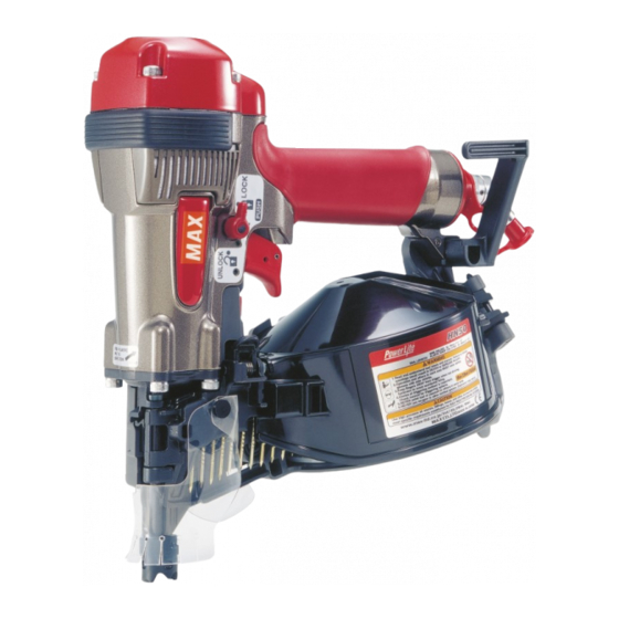
⑦ Grip ⑧ Exhaust Cover ⑨ Trigger Lock Dial ⑩ Air Plug ⑪ End Plug Cap ⑫ Hook 2. TOOL SPECIFICATIONS PRODUCT NO. HN50 261 mm (10-1/4”) HEIGHT 128 mm (5”) WIDTH 275 mm (10-3/4”) LENGTH 1.6 kg (3.53 lbs.) - Page 8 4. TECHNICAL DATA ① NOISE A-weighted single-event sound power level ------ LWA, 1s, d 90.7 dB A-weighted single-event emission sound pressure level at work station ------ LpA, 1s, d 83.8 dB These values are determined and documented in accordance to EN12549 : 1999. ②...
-
Page 9: Air Supply And Connections
To use the tool, you always need the special air compressor and Air hose air hose (MAX PowerLite Compressor and MAX PowerLite Hose). Use of high-pressure gas (for example, oxygen, acetylene, etc.) causes abnormal combustion, possibly resulting in explosion. Use only the special air compressor and air hose. -
Page 10: Instructions For Operation
4. INSTRUCTIONS FOR OPERATION Read section titled “SAFETY INSTRUCTIONS”. 1. BEFORE OPERATION ① Wear Safety Glasses or Goggles. ② Do not connect the air supply. ③ Inspect screw tightness. ④ Check operation of the contact arm & trigger if moving smoothly. ⑤... - Page 11 ③ Nail loading: Place a coil of nails over the Nail Post in the Magazine. Uncoil enough nails to reach the Feed Pawl, and place the second nail between the teeth on the Feed Pawl. The nail heads fit in slot on Nose. Feed Pawl Nail ④...
- Page 12 MODEL IDENTIFICATION CONTACT TRIP The common operating procedure on “Contact Trip” tools is for the operator to contact the work to actuate the trip mechanism while keeping the Trigger pulled, thus driving a fastener each time the work is contacted. This will allow rapid fastener placement on many jobs, such as sheathing, decking and pallet assembly.
- Page 13 CONTACT FIRE OPERATION (CONTACT TRIP) For contact fire operation, hold the Trigger and depress the Contact Arm against the work surface. PROCEDURE ① Hold the Trigger. ② Depress the Contact Arm. SINGLE FIRE OPERATION (ANTI-DOUBLE FIRE MECHANISM AND SEQUENTIAL TRIP) For single fire operation, depress the Contact Arm against the work surface and pull the Trigger.
- Page 14 CONTACT TIP ALWAYS disconnect air supply before attaching / detaching the contact tip. Attach the Contact Tip on the tip of Contact Arm, when driving nails to a soft material. Contact Arm The Contact Tip can be kept on the Arm Cover when not using. Contact Tip Magazine WHEN USING THE TOOL FOR STEEL PLATES...
-
Page 15: Maintain For Performance
④ All quality tools will eventually require servicing or replacement of parts because of wear from the normal use. 7. TROUBLE SHOOTING/REPAIRS The troubleshooting and/or repairs shall be carried out only by the MAX CO., LTD.authorised distributors or by other specialists. - Page 17 ・ The content of this manual might be changed without notice for improvement. 6-6 NIHONBASHI-HAKOZAKI-CHO, CHUO-KU, TOKYO, JAPAN Tel: (03) 3669-8131 Telefax: (03) 3669-7104 www.max-ltd.co.jp/int/ (GLOBAL Site) www.max-europe.com (EUROPE Site) ★061201-00/00 PRINTED IN JAPAN...
Need help?
Do you have a question about the HN50 and is the answer not in the manual?
Questions and answers