Advertisement
Quick Links
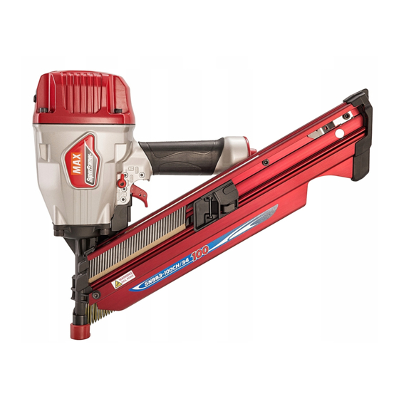
SN883-90CH/34
SN883-100CH/34
34 DEGREE CLIPPED HEAD
FRAMING STICK NAILER
34-GRAD BEFESTIGTER RAHMEN-
STOCKHAUPTNAGLER
CLOUEUSE À MANCHE D'ENCADREMENT
DE TÊTE COUPÉE À 34 DEGRÉS
INCHIODATRICE A MANICA DI QUADRO
DI TESTA TAGLIATA A 34 GRADI
CLAVADORA DE BARRA DE MARCO
DE CABEZA CORTADA A 34 GRASDOS
OPERATING and MAINTENANCE MANUAL
MANUEL D'UTILISATION et D'ENTRETIEN
MANUALE DI FUNZIONAMENTO E MANUTENZIONE
MANUAL DE OPERACIONES Y MANTENIMIENTO
BEFORE USING THIS TOOL, STUDY THIS MANUAL TO ENSURE SAFETY WARNING
AND INSTRUCTIONS.
KEEP THESE INSTRUCTIONS WITH THE TOOL FOR FUTURE REFERENCE.
WARNING
LESEN SIE VOR INBETRIEBNAHME DES GERÄTES DIE GEBRAUCHS- UND SICHER-
HEITSHINWEISE. BITTE BEWAHREN SIE DIE GEBRAUCHS- UND SICHERHEITSHIN-
WEISE AUF, DAMIT SIE AUCH SPÄTER EINGESEHEN WERDEN KÖNNEN.
ACHTUNG
AVANT D'UTILISER CET OUTIL, LIRE CE MANUEL ET LES CONSIGNES DE SECURITE
AFIN DE GARANTIR UN FONCTIONNEMENT SUR.
CONSERVER CE MANUEL EN LIEU SUR AVEC L'OUTIL AFIN DE POUVOIR LE CON-
SULTER ULTERIEUREMENT.
AVERTISSEMENT
PRIMA DI USARE QUESTA MACCHINA, STUDIARE IL MANUALE PER PRENDERE ATTO
DEGLI AVVERTIMENTI E DELLE ISTRUZIONIPER LA SICUREZZA.
TENERE QUESTE ISTRUZIONI INSIEME ALLO STRUMENTO PER CONSULTAZIONI FU-
TURE.
ATTENZIONE
PARA EVITAR GRAVES DAÑOS PERSONALES O EN LA PROPIEDAD.
ANTES DE EMPLEAR LA HERRAMIENTA, LEER CON ATENCIÓN Y COMPRENDER LOS
SIGUIENTES INSTRUCCIONES DE SEGURIDAD.
ATENCIÓN
BETRIEBSANLEITUNG
(CE)
(CE)
Advertisement

Related Manuals for Max SN883-90CH/34(CE)


Summary of Contents for Max SN883-90CH/34(CE)
- Page 1 SN883-90CH/34 (CE) SN883-100CH/34 (CE) 34 DEGREE CLIPPED HEAD FRAMING STICK NAILER 34-GRAD BEFESTIGTER RAHMEN- STOCKHAUPTNAGLER CLOUEUSE À MANCHE D’ENCADREMENT DE TÊTE COUPÉE À 34 DEGRÉS INCHIODATRICE A MANICA DI QUADRO DI TESTA TAGLIATA A 34 GRADI CLAVADORA DE BARRA DE MARCO DE CABEZA CORTADA A 34 GRASDOS OPERATING and MAINTENANCE MANUAL BETRIEBSANLEITUNG...
- Page 2 Ανατρέξτε στο CD-ROM ή στην τοποθεσία Web. TÜRKÇE CD-ROM veya Web sitesine bakınız. РУССКИЙ См. на компакт-диске или на веб-сайте. www.max-ltd.co.jp/int/eu/ DEFINITIONS OF SIGNAL WORDS WARNING: Indicates a potentially hazardous situation which, if not avoided, could result in death or serious injury.
-
Page 3: Table Of Contents
ENGLISH OPERATING and MAINTENANCE MANUAL INDEX 1. SAFETY INSTRUCTIONS ..........3 2. SPECIFICATIONS AND TECHNICAL DATA ....7 3. AIR SUPPLY AND CONNECTIONS ........8 4. INSTRUCTIONS FOR OPERATION ........ 10 5. MAINTENANCE..............15 6. STORAGE ................ 15 7. TROUBLE SHOOTING/REPAIRS........15 BEFORE USING THIS TOOL, STUDY THIS MANUAL TO ENSURE SAFETY WARNING AND IN- STRUCTIONS. - Page 4 NOTE: Non-side shielded spectacles and face shields alone do not provide adequate protection. Thinner Gasoline 5. DO NOT OPERATE THE TOOL NEAR A FLAMMABLE SUBSTANCE Never operate the tool near a flammable substance (e.g., thinner, gasoline, etc.). Vol- 2. EAR PROTECTION MAY BE REQUIRED atile fumes from these substances could be IN SOME ENVIRONMENTS drawn into the compressor and compressed...
- Page 5 12. USE SPECIFIED FASTENERS (SEE PAGE 7) The use of fasteners other than specified fasteners will cause the tool malfunction. Be sure to use only specified fasteners when operating the tool. 9. INSPECT SCREW TIGHTNESS Loose or improperly installed screws or bolts cause accidents and tool damage when the tool is put into operation.
- Page 6 Secure the hose at a point close to the area label. you are going to drive fasteners. Accidents • Do not modify the tool from original design may be caused due to the hose being pulled or function without approval by MAX CO., inadvertently or getting caught. LTD.
-
Page 7: Specifications And Technical Data
2. SPECIFICATIONS AND TECHNICAL DATA 1. NAME OF PARTS 1 Frame 6 Trigger 2 Cylinder Cap 7 Grip 3 Contact Arm 8 Exhaust Cover 4 Nose 9 Pusher 5 Magazine 0 Adjustment Dial 2. TOOL SPECIFICATIONS PRODUCT NO. SN883-90CH/34 (CE) SN883-100CH/34 (CE) HEIGHT 316 mm (12-1/2") -
Page 8: Air Supply And Connections
3. AIR SUPPLY AND CON- TOOL AIR FITTINGS: NECTIONS This tool uses a 3/8" N.P.T. male plug. The in- side diameter should be 9.9mm (.39") or larger. The fitting must be capable of discharging tool air pressure when disconnected from the air supply. WARNING RECOMMENDED OPERATING PRES- SURE:... - Page 9 HOSES: Hose has a min. ID of 6 mm (1/4") and max. length of no more than 5 meters (17"). The supply hose should contain a fitting that will provide "quick disconnecting" from the male plug on the tool.
-
Page 10: Instructions For Operation
4. INSTRUCTIONS FOR OP- ERATION READ SECTION TITLED "SAFETY IN- STRUCTIONS". WARNING 1. BEFORE OPERATION Check the following prior operation. Keep hands and body away from the discharge 1 Wear Safety Glasses or Goggles. outlet when driving the fasteners because of 2 Do not connect the air supply. - Page 11 MODEL IDENTIFICATION CONTACT TRIP MODEL with ANTI-DOUBLE Pusher FIRE MECHANISM The anti-double fire mechanism (US patent 5597106, UK patent 2286790) is installed on this tool. The common operating procedure on "Contact Trip" tools is for the operator to contact the work to actuate the trip mechanism while keeping the trigger pulled, thus driving a fastener each time the work is contacted.
- Page 12 DRIVING FASTENERS SEQUENTIAL TRIP The Sequential Trip requires the operator to hold CONTACT FIRE OPERATION the tool against the work before pulling the trig- For contact fire operation, hold the Trigger and ger. This makes accurate fastener placement depress the Contact Arm against the work sur- easier, for instance on framing, toe nailing and face.
- Page 13 ADJUSTABLE DIAL DEPTH CONTROL CONTACT TIP Adjustment Dial Deeper Shallow Contact Arm Contact Tip WARNING WARNING ALWAYS disconnect air supply before dial ad- ALWAYS disconnect air supply before attach- justment. ing / detaching the contact tip. 1 With air pressure set, drive nails into a repre- Attach the Contact Tip on the tip of Contact Arm, sentative material sample to determine if ad- when driving nails to a soft material.
- Page 14 REMOVING JAMMED NAILS Nail Stopper 2 Push the Nail Stopper, and remove the strip nails from inside of the Magazine. WARNING ALWAYS disconnect air supply before remov- ing jammed nails. Pusher Lever 3 Pull and stayed the Pusher with hand. 4 Remove the jammed nail from the Nose us- ing a punch or a slotted screw driver.
-
Page 15: Maintenance
The troubleshooting and/or repairs shall be car- and tool should be no longer than 5 m since ried out only by the MAX CO., LTD. authorised a longer length results in a reduction in air distributors or by other specialists.
Need help?
Do you have a question about the SN883-90CH/34(CE) and is the answer not in the manual?
Questions and answers