Table of Contents
Advertisement
INSTALLATION, OPERATING AND
SERVICE INSTRUCTIONS FOR
9700609
As an ENERGY STAR
Partner, U.S. Boiler Company has determined that the MPO-IQ™ boiler meets the ENERGY STAR
®
guidelines for energy efficiency established by the United States Environmental Protection Agency (EPA).
For service or repairs to boiler, call your heating contractor. When seeking information on boiler, provide
Boiler Model Number and Serial Number as shown on Rating Label.
Boiler Model Number
MPO - IQ
Heating Contractor
Address
103859-05 - 10/14
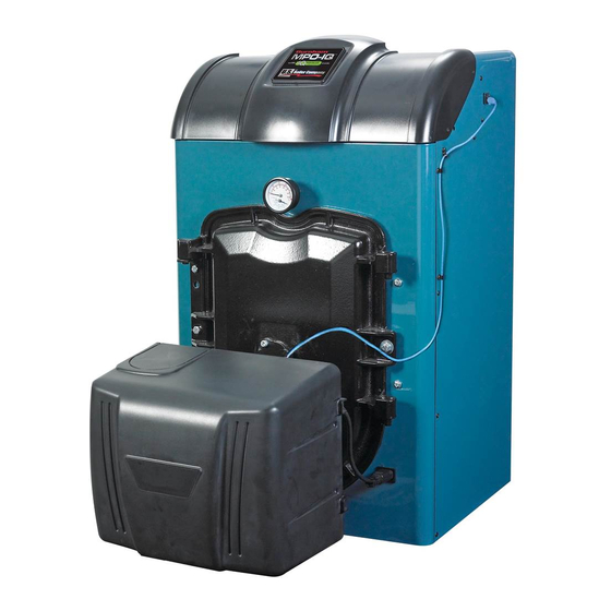
MPO - IQ™
3-PASS OIL Boiler
Boiler Serial Number
Installation Date
Phone Number
Price - $5.00
®
Advertisement
Table of Contents
Troubleshooting

Related Manuals for U.S. Boiler Company MPO - IQ


Summary of Contents for U.S. Boiler Company MPO - IQ
- Page 1 MPO - IQ™ 3-PASS OIL Boiler 9700609 As an ENERGY STAR Partner, U.S. Boiler Company has determined that the MPO-IQ™ boiler meets the ENERGY STAR ® ® guidelines for energy efficiency established by the United States Environmental Protection Agency (EPA).
- Page 2 IMPORTANT INFORMATION - READ CAREFULLY All boilers must be installed in accordance with National, State and Local Plumbing, Heating and Electrical Codes and the regulations of the serving utilities. These Codes and Regulations may differ from this instruction manual. Authorities having jurisdiction should be consulted before installations are made.
- Page 3 DANGER DO NOT store or use gasoline or other flammable vapors or liquids in the vicinity of this or any other appliance. WARNING Improper installation, adjustment, alteration, service or maintenance can cause property damage, personal injury or loss of life. Failure to follow all instructions in the proper order can cause personal injury or death. Read and understand all instructions, including all those contained in component manufacturers manuals which are provided with the boiler before installing, starting-up, operating, maintaining or servicing this boiler.
-
Page 4: Table Of Contents
WARNING This boiler must be properly vented. The chimney must be inspected for any obstructions and cleaned prior to each heating season. A clean and unobstructed chimney flue is necessary to produce the minimum draft required to safely evacuate noxious fumes that could cause personal injury or loss of life. Evidence of loose debris and or condensate induced stains at the base of the chimney flue, connector or smokepipe joints may be signs of condensing flue gases. - Page 5 Congratulations on your purchase of a new MPO-IQ™ boiler—designed and constructed to provide you with years of reliable service. • ENERGY STAR™ efficiency – friendly on the environment and your wallet. • Cast iron heat exchanger – for reliability and durability, nothing beats a cast iron heat exchanger. •...
-
Page 8: I. Pre-Installation
I. PRE-INSTALLATION A. INSPECT SHIPMENT carefully for any signs of • 36" for flueway cleaning (MPO-IQ231) damage. b. Clearance from Jacket Side Panels - • 19" for burner swing door, if opened fully with 1. All equipment is carefully manufactured, inspected and burner mounted, otherwise 1"... - Page 9 I. PRE-INSTALLATION (continued) a. Outdoor air for combustion may be provided C. PROVIDE COMBUSTION AND VENTILATION with an optional Fresh Air Accessory Kit (ONLY AIR. Local and National Codes may apply and should AVAILABLE WITH BECKETT BURNER). be referenced. Metal cover applications, P/N 611280031. Plastic WARNING cover applications, P/N 102119-01.
- Page 10 I. PRE-INSTALLATION (continued) 6. Louvers and Grilles of Ventilation Ducts TABLE 2: DIRECT VENT CONFIGURATION a. All outside openings should be screened and louvered. COMPONENTS Screens used should not be smaller than 1/4 inch mesh. Beckett NX Direct Vent Louvers will prevent the entrance of rain and snow. Boiler FOVP Carton Part Oil Burner...
- Page 11 II. PACKAGED BOILER ASSEMBLY - TRIM & CONTROLS A. REMOVE CRATE. through rear legs until wooden blocks can be removed (see Figure 3). Slowly allow the weight of the boiler 1. Remove all fasteners at crate skid. to tilt backward until rear legs rest on floor. 2.
- Page 12 II. PACKAGED BOILER ASSEMBLY - TRIM & CONTROLS (cont'd) Figure 4A: Partial Front View - Burner Swing Door Mounted to Boiler - Fully Closed and Secured Step 4. Disconnect burner power cord from receptacle machine screw) from right side of door located in lower right corner of jacket front panel.
- Page 13 II. PACKAGED BOILER ASSEMBLY - TRIM & CONTROLS (cont'd) Figure 4B: Top View - Burner Swing Door Mounted to Cast Iron Block Assembly (Jacket Removed for Clarity)
- Page 14 II. PACKAGED BOILER ASSEMBLY - TRIM & CONTROLS (cont'd) Step 2. If necessary, place your right hand under the E. INSPECT SWING DOOR INSULATION AND ROPE burner air tube to lift upward. Lift the door up unto GASKET. the built-in cast ramp/door rest (protruding from the 1.
- Page 15 II. PACKAGED BOILER ASSEMBLY - TRIM & CONTROLS (cont'd) Figure 4D: Burner Swing Door Insulation 1. Install return injector piping and relief valve, refer to Figure 5. Step a. Locate the return pipe fittings and injector. Apply sealant to the 2” NPT injector threads. Insert injector into 2”...
- Page 16 II. PACKAGED BOILER ASSEMBLY - TRIM & CONTROLS (cont'd) Figure 6: Piping Arrangement for Drain Valve and Indirect Water Heating Return • 1-1/2" NPT horizontal left or right side return Step c. Apply sealant to 3/4" NPT thread on drain valve. piping - Install relief valve vertically in 3/4"...
- Page 17 II. PACKAGED BOILER ASSEMBLY - TRIM & CONTROLS (cont'd) TABLE 3: BAFFLE USAGE WARNING Baffle Usage Wire an additional safety limit such as a low water Boiler Model cut-off or temperature limit device, other than an IQ Pass Pass Control device, in series with the 120V circuit used to power the boiler.
- Page 18 II. PACKAGED BOILER ASSEMBLY - TRIM & CONTROLS (cont'd) Figure 8: Baffle Orientation in Flueways Step a. Install stainless steel baffles provided in pass flueway on right side of boiler, hold baffle miscellaneous parts carton as follows, refer to Table with word “Right”...
- Page 19 II. PACKAGED BOILER ASSEMBLY - TRIM & CONTROLS (cont'd) Figure 9: Oil Burner Installation (Beckett shown) 7. Install oil burner. (See Figure 9) Step e. Insert oil burner into the opening of burner swing door. Align and engage keyhole slot in burner flange Step a.
- Page 20 III. UNIT-PAK BOILER ASSEMBLY - TRIM & CONTROLS MPO-IQ Unit-Pak Boiler Assembly Shipment (-LLU) Content Check List (see Figure 10) 1. ___ Cast Iron Section/Burner Swing Door/Smoke Box Assembly Mounted on Shipping Skid: ____ MPO-IQ84/115 – Part # 103071-02 / 100045-01 / 100021-01 ____ MPO-IQ147 –...
- Page 21 III. UNIT-PAK BOILER ASSEMBLY - TRIM & CONTROLS (continued) A. REMOVAL OF CAST IRON SECTION/BURNER rear legs, until wooden block(s) can be removed (see SWING DOOR / SMOKE BOx ASSEMBLY FROM Figure 11). Slowly allow the weight of boiler to tilt SKID.
- Page 23 III. UNIT-PAK BOILER ASSEMBLY - TRIM & CONTROLS (continued) E. FLUEWAY BAFFLE INSTALLATION. Refer to Section front section right side. These four front section bosses II, Paragraph F. are front jacket panel and door mounting bracket attachment points. F. CLOSING / SECURING BURNER SWING DOOR. 2.
- Page 24 III. UNIT-PAK BOILER ASSEMBLY - TRIM & CONTROLS (continued) 5. Position left Cleanout Cover over rear section cleanout CAUTION opening, align section boss holes with Cleanout Cover holes, install both 5/16”-18 – 7/8” hex head cap screws Do not apply pressure to gauge case, as this may hand tight, then, alternately tighten them with open end result in inaccurate readings.
- Page 25 III. UNIT-PAK BOILER ASSEMBLY - TRIM & CONTROLS (continued) 11. Locate the Jacket Front Cover from Control Carton. See N. FIELD ASSEMBLY OF BOILER TRIM AND also "Repair Parts" Section, "Jacket Assembly" illustration BURNERS. Refer to Section II, Paragraph F. for parts identification.
-
Page 26: Iv. Water Boiler Piping
U.S. Boiler Company recommends sizing the 3. If an indirect water heater is used, priority zoning can be system circulator to supply sufficient flow (GPM) used. - Page 29 IV. WATER BOILER PIPING (continued) 5. See Figure 14 for suggested near boiler piping of It is recommended that the LWCO control is installed Option Card Controls. above the boiler to provide the highest level of protection. However, where the LWCO control is approved by the WARNING LWCO control manufacturer for installation in a high boiler tapping of a water boiler, the use of the listed LWCO...
-
Page 30: V. Natural Draft Venting
V. NATURAL DRAFT VENTING (All Boiler Models) susceptible to this condition. Under no circumstances A. CHIMNEY VENTING shall a chimney of this condition be used until it meets 1. Chimney venting is an important part of a safe and efficient the requirements of NFPA 211 or CSA B139-04. - Page 31 V. NATURAL DRAFT VENTING (continued) Figure 15: Recommended Vent Pipe Arrangement and Chimney Requirements Figure 16: Proper and Improper Locations of Draft Regulator...
- Page 32 V. NATURAL DRAFT VENTING (continued) CAUTION DANGER Any doubt on the condition of a chimney or it’s Any signs of condensate seepage at the base of ability to prevent the generation and accumulation the chimney shall be inspected immediately. The discoloration may be a sign of chimney damage and of flue gas condensate, must be relined according to NFPA 31 (United States) or CSA B139 (Canada).
- Page 33 V. NATURAL DRAFT VENTING (continued) E. MINIMUM CLEARANCES WARNING See Figure 2A for details regarding clearances to combustibles for the boiler. Using outdoor air in the middle of winter may result in lower stack temperatures and chimney F. OPTIONAL AIR INTAKE PIPING INSTALLATION degradation.
-
Page 34: Vi. Direct Venting / Air Intake Piping
VI. DIRECT VENTING / AIR INTAKE PIPING (Boiler Models MPO-IQ147 thru 231 ONLY) A. GENERAL GUIDELINES WARNING 1. Direct Vent system must be installed in accordance with these instructions and applicable provisions of local This venting system must be installed by a building codes. - Page 35 VI. DIRECT VENTING / AIR INTAKE PIPING (continued) e. Not less than 3 ft (as measured to side of vent TABLE 5: WALL CUTOUT DIMENSIONS termination) from an inside corner of an L-shaped structure. Direct Vent Conversion "L" Dimension Boiler Model No. Kit Part No.
- Page 36 VI. DIRECT VENTING / AIR INTAKE PIPING (continued) D. INSTALLING THE FLEx OIL VENT PIPE FROM THE VENT TERMINATION TO THE BOILER FLUE OUTLET 1. The venting system (vent pipe and all connectors) shall be installed in accordance with the applicable provisions of any local codes, and, in United States, requirements of NFPA 31- Standard for the Installation of Oil-Burning Equipment and NFPA211- Standard for Chimney,...
- Page 37 VI. DIRECT VENTING / AIR INTAKE PIPING (continued) TABLE 6: FLEx VENT / VENT TERMINATION PIPE DIAMETERS Vent Hood Flex Oil Vent Pipe Boiler Flue Outlet * Flue Outlet Collar to Boiler Model No. Inner Pipe Inner Pipe Diameter Collar OD (Inch) Vent Pipe Adapter (Inch) Diameter (Inch) (Inch)
- Page 38 VI. DIRECT VENTING / AIR INTAKE PIPING (continued) Figure 25: Vent Pipe Ends, Vent Termination and Appliance Adapter Sealing F. CONNECTING FLEx OIL VENT PIPE TO APPLIANCE 7. Apply sealant; firstly, between the stop bead and retainer ADAPTER AND DIRECT VENT TERMINATION bead at the end of the vent termination inner pipe;...
- Page 39 VI. DIRECT VENTING / AIR INTAKE PIPING (continued) 2. Maximum air intake pipe length is 40 equivalent feet. WARNING DO NOT reduce size of air intake pipe. 3. Start at burner and work towards Direct Vent termination air intake. 4. Remove burner cover. Loosen two screws securing outside air duct bracket to burner cover mounting plate.
- Page 40 VI. DIRECT VENTING / AIR INTAKE PIPING (continued) 12. Assemble the vacuum relief valve balance weight onto 14. Install remainder of air intake piping to Direct Vent the gate. Refer to the vacuum relief valve manufacturer’s Termination air intake collar, securing each joint with at instructions for details.
-
Page 41: Vii. Electrical
VII. ELECTRICAL DANGER Positively assure all electrical connections are unpowered before attempting installation or service of electrical components or connections of the boiler or building. Lock out all electrical boxes with padlock once power is turned off. WARNING Failure to properly wire electrical connections to the boiler may result in serious physical harm. Electrical power may be from more than one source. - Page 44 VII. ELECTRICAL (continued) Figure 28C: Ladder Diagram...
-
Page 45: Viii. Oil Piping
VIII. OIL PIPING A. GENERAL WARNING 1. Use flexible oil line(s) so the burner swing door can be Under no circumstances can copper with sweat opened without disconnecting the oil supply piping. style connectors be used. 2. A supply line fuel oil filter is recommended as a minimum for all firing rates but a pleated paper fuel oil filter is recommended for the firing rates below 1.0 GPH to NOTICE... - Page 46 VIII. OIL PIPING (continued) C. TWO PIPE OIL LINES 3. Under no circumstances is a manual shutoff valve to be located on the return line of a two pipe system. 1. For two piped systems, where more lift is required, the Accidental closure of the return line will rupture the oil two-stage fuel unit is recommended.
-
Page 47: Ix. System Start-Up
Ix. SYSTEM START-UP WARNING All boilers equipped with burner swing door have a potential hazard which can cause severe property damage, personal injury or loss of life if ignored. Before opening swing door, turn off service switch to boiler to prevent accidental firing of burner outside the combustion chamber. - Page 48 Ix. SYSTEM START-UP (continued) D. START OIL BURNER. made recheck for a draft of zero inches water column ("w.c.) in the canopy. Replace plug at completion. 1. Open oil supply to burner and vent fitting on fuel pump. See Tables 15A thru 15C and 16 (at rear of this manual) for details regarding the overfire pressure when baffles 2.
- Page 49 Ix. SYSTEM START-UP (continued) e. T-T Jumper: All R7284 models have internal "TT WARNING Configured ON" parameters set to "ON". The R7284 has an LCD display and simply displays Before installation of the boiler is considered lockout and flame status on it. complete, the operation of all boiler controls must f Cad Cell Resistance Check: For proper operation be checked, particularly the primary control and...
- Page 50 Ix. SYSTEM START-UP (continued) • d. Power Failure Check: After Flame is established, If safety switch shuts down burner and resistance is above 1600 OHMS, open line turn the power off to the control/burner. The burner switch to boiler. Access cad cell under should shut down safely.
- Page 51 Important Product Safety Information Refractory Ceramic Fiber Product Warning: The Repair Parts list designates parts that contain refractory ceramic fibers (RCF). RCF has been classified as a possible human carcinogen. When exposed to temperatures above 1805°F, such as during direct flame contact, RCF changes into crystalline silica, a known carcinogen.
-
Page 52: X. Operating
x. OPERATING Figure 33: Boiler Control & Option Panel Orientation A. BOILER SEQUENCE OF OPERATION TABLE 9: SEQUENCE OF OPERATION 1. The boiler's sequence of operation is shown in Table 9. Status Code Displayed in STA Mode 2. When there is a call for heat the boiler control starts the Status Description system circulator and the thermal purge (circulator pre-... - Page 53 x. OPERATING (continued) the trial for ignition, the oil primary control will shut Status Number Displayed in STA Mode the burner down and enter into a hard lockout. The Oil Standby Primary must be reset manually before the burner can be Pre-purge restarted.
- Page 54 x. OPERATING (continued) F. CHANGING THE ADJUSTABLE PARAMETERS 3. Circulator Overrun Time (OR_) Circulator Overrun Time (also called “circulator off To adjust parameters such as the High Limit Setpoint and delay” or “circulator post purge”) continues circulator High Limit Differential: operation after a call for heat has ended, sending 1.
- Page 55 x. OPERATING (continued) 7. Priority Time (Pt_) control two independent heating zones. Refer to Table 12. A "TT" input causes a call for heat and When the Priority Time parameter is set to “on” and energizes the System Circulator output to service Domestic Hot Water (DHW) call for heat is “on”...
- Page 56 x. OPERATING (continued) c. External Low Limit, Parameter ZC = ELL TABLE 13: ExTERNAL LOW LIMIT, PARAMETER ZC_= ELL The boiler control is capable of functioning as a warm start control when external limit control Call for Heat Circulator Status is installed that closes a contact when boiler water temperature falls below a setpoint.
-
Page 57: Xi. Maintenance & Service Instructions
xI. MAINTENANCE AND SERVICE INSTRUCTIONS A. MAINTENANCE OF LOW WATER CUT-OFF CAUTION DEVICES (when installed) See Instructions provided with Low Water Cut-off Option Exercise caution when handling phosphoric acid Card for Installation Instructions. and follow the instruction label on its container. WARNING h. - Page 58 xI. MAINTENANCE AND SERVICE INSTRUCTIONS (continued) c. Remove relief valve using extreme care to avoid IMPORTANT damaging it. d. Add an appropriate amount of recommended boil out IF, DURING NORMAL OPERATION, IT IS NECESSARY compound. TO ADD MORE WATER THAN INDICATED BELOW, e.
-
Page 59: Xii. Boiler Cleaning
xII. BOILER CLEANING WARNING All boiler cleaning must be completed with burner service switch turned off. Boilers equipped with burner swing door have a potential hazard which can cause severe property damage, personal injury or loss of life if ignored. Before opening swing door, turn off service switch to boiler to prevent accidental firing of burner outside the combustion chamber. - Page 60 xII. BOILER CLEANING (continued) Figure 35: Cleaning of Boiler Flueways WARNING The boiler must be connected to an approved chimney in good condition. Serious property damage could result if the boiler is connected to a dirty or inadequate chimney. The interior of the chimney flue must be inspected and cleaned before the start of the heating season and should be inspected periodically throughout the heating season for any obstructions.
-
Page 61: Xiii. Trouble Shooting
xIII. TROUBLE SHOOTING A. COMBUSTION above grade or has fuel lines in a shallow bury is a good candidate for cold oil. The best solution is to locate the 1. NOZZLES — Although the nozzle is a relatively tank near the boiler in the basement utility room or bury inexpensive device, its function is critical to the successful the tank and lines deep enough to keep the oil above 40°F. - Page 62 xIII. TROUBLE SHOOTING (continued) 3. Control locks out after Trial For Ignition (TFI). NOTICE a. No oil to burner. b. Shorted electrodes. If flame is not established within 15 seconds of oil valve actuation (known as Trial For Ignition c. Nozzle clogged. [TFI]) lockout will occur.
- Page 63 xIII. TROUBLE SHOOTING (continued) make sure that they are tight. Also, check the wiring 4. A defective control or component is generally the least on the boiler against the wiring diagram in Figures likely cause. Before replacing a component, try to rule 28A, 28B and 28C.
- Page 64 xIII. TROUBLE SHOOTING (continued) E. USE BOILER CONTROL DISPLAY ERR AND ERP NUMBERS TO DIRECT TROUBLESHOOTING (continued) TABLE 14B: ExTERNAL DEVICE (Oil Primary, Option Card, etc.) ERROR NUMBERS Display Status Recommended Corrective Actions The cad cell resistance is higher than normal while running, the system is in need of a tune Warning, Cad Cell - Check for proper alignment of the cad cell and clean the eye if necessary.
- Page 65 xIII. TROUBLE SHOOTING (continued) E. USE BOILER CONTROL DISPLAY ERR AND ERP NUMBERS TO DIRECT TROUBLESHOOTING (continued) TABLE 14B: ExTERNAL DEVICE (Oil Primary, Option Card, etc.) ERROR NUMBER (continued) Display Status Recommended Corrective Actions Flame was proven during the valve on delay period. Check the oil valve for proper Flame Out of Sequence, operation.
- Page 66 xIII. TROUBLE SHOOTING (continued) F. USE BOILER CONTROL DISPLAY STA (STATUS) NUMBER TO GUIDE TROUBLESHOOTING The Boiler Control will flash “STA” followed by a number. Use this number to identify the boiler problem in the table below: 1. Burner and Circulator Off Display / Status Recommended Corrective Action The boiler has not detected a call for heat (hr = off and dh = off).
- Page 67 xIII. TROUBLE SHOOTING (continued) F. USE BOILER CONTROL DISPLAY STA (STATUS) NUMBER TO GUIDE TROUBLESHOOTING (continued) 5. Burner will not come on Display / Status Recommended Corrective Action When a hard lockout occurs the burner shuts down and will not restart until the Oil Primary’s manual reset button is pressed.
- Page 68 xIII. TROUBLE SHOOTING (continued) G. USE OPTION PANEL DISPLAY TO DIRECT TROUBLESHOOTING If Boiler Control Shows Status Code “STA 15": The Boiler Control is “Waiting for Limit to Close and Option Panel display (display to right) will show one of the following status codes: Option Panel Display Shows "Err"...
-
Page 69: Xiv. Repair Parts
All MPO-IQ™ Boiler Repair Parts may be obtained through your local U.S. Boiler Company Wholesale distributor. Should you require assistance in locating a U.S. Boiler Company Distributor in your area, or have questions regarding the availability of U.S. Boiler Company products or repair parts, please contact... - Page 71 xIV. REPAIR PARTS (continued) Item Description Part No. MPO-IQ84 MPO-IQ115 MPO-IQ147 MPO-IQ189 MPO-IQ231 1. BARE BOILER ASSEMBLY Cast Iron Block Assembly - 2 Section 103071-02 Cast Iron Block Assembly - 3 Section 103071-03 Cast Iron Block Assembly - 4 Section 103071-04 Cast Iron Block Assembly - 5 Section 103071-05...
- Page 73 xIV. REPAIR PARTS (continued) Item Description Part No. MPO-IQ84 MPO-IQ115 MPO-IQ147 MPO-IQ189 MPO-IQ231 2. JACKET ASSEMBLY Jacket Front Panel Assembly 103053-01 w/Insulation Power Outlet Receptacle, Heyco #0937 8136522 #8 x 1/2” Sheet Metal Screw, Black Oxide 80860061 Jacket Rear Panel Assembly 103054-01 w/Insulation Snap Bushing, Heyco #2240...
- Page 75 xIV. REPAIR PARTS (continued) Item Description Part No. MPO-IQ84 MPO-IQ115 MPO-IQ147 MPO-IQ189 MPO-IQ231 3. MPO-IQ84 Thru MPO-IQ231 WATER BOILERS - TRIM AND CONTROLS Beckett AFG Oil Burner w/Gasket for: Natural Draft MPO-IQ84 Spec No. BCB9502 104506-02 MPO-IQ115 Spec No. BCB9503 104507-02 MPO-IQ147 Spec No.
- Page 76 xIV. REPAIR PARTS (continued) Item Description Part No. MPO-IQ84 MPO-IQ115 MPO-IQ147 MPO-IQ189 MPO-IQ231 4. CONTROLS IQ Oil Boiler Control 103851-01 IQ Option Control Panel 102291-01 Line Voltage Harness 103058-02 Low Voltage Harness 103059-03 Burner-ECOM Harness 103060-02 Transformer 102516-01 Limit Rated Temperature Sensor, 103195-01 Shown 12"...
- Page 77 xIV. REPAIR PARTS (continued) Item No. Description Part No. MPO-IQ147 MPO-IQ189 MPO-IQ231 5. DIRECT VENT KITS AND PARTS Direct Vent Conversion Kit , 5-6 102130-02 Direct Vent Conversion Kit, 6-7 102130-03 Appliance Adapter, FDVS, 5-6 100234-02 Appliance Adapter, FDVS, 6-7 100234-03 6"...
-
Page 79: Natural Draft Applications
xIV. REPAIR PARTS (continued) BECKETT AFG OIL BURNER PART NOS. FOR MPO-IQ SERIES BOILERS NATURAL DRAFT APPLICATIONS NOTE: When ordering parts always give the serial and model numbers shown on the boiler and burner. Also provide the name of the part(s) and part number as listed below. Boiler Model MPO-IQ84 MPO-IQ115... - Page 81 xIV. REPAIR PARTS (continued) BECKETT Nx OIL BURNER PART NOS. FOR MPO-IQ SERIES BOILERS DIRECT VENT APPLICATIONS NOTE: When ordering parts always give the serial and model numbers shown on the boiler and burner. Also provide the name of the part(s) and part number as listed below. MPO-IQ147 MPO-IQ189 MPO-IQ231...
- Page 82 xIV. REPAIR PARTS (continued) RIELLO OIL BURNER PART NUMBERS FOR MPO-IQ SERIES BOILERS NOTE: When ordering parts always give the serial and model numbers shown on the boiler and burner. Refer to Models F3 & F5 Installation Manual, Riello 40 Series Residential Oil Burners (C6501010) or Model F10 Installation Manual, Riello 40 Series Residential Oil Burners (2902554) for an exploded view of the burner and a list of spare parts.
-
Page 83: Xv. Burner Specifications
xV. BURNER SPECIFICATIONS TABLE 15A: BECKETT AFG BURNER SPECIFICATIONS - CHIMNEY VENT Baffles Baffles Approx. Approx. Approx. Burner Pump Head Insertion Baffle Stack Temp. Boiler Burner Air Band Shipped Breech Approx. Approx. Input Nozzle Shutter Pressure Type Depth Location Increase Model Model (setting) - Page 84 xV. BURNER SPECIFICATIONS (continued) TABLE 15C: CARLIN EZ BURNER SPECIFICATIONS - CHIMNEY VENT Baffles Approx. Baffles IN Approx. Burner Pump Insertion Approx. Baffle Stack Temp. Approx. Boiler Burner Head Air Tube Breech Approx. Input Nozzle Pressure Depth Shipped Location Increase Overfire Model Model...
- Page 85 • Error codes can be displayed on EnviraCOM-enabled programmable thermostat • Built-in diagnostics • U.S. Boiler Company factory engineered and tested as part of a complete system IQ Oil Boiler Control: P/N 103851-01 The IQ Oil Boiler Control replaces the familiar Honeywell L7248 electronic Aquastat and contains several additional features. These unique features allow the IQ Oil Boiler Control to connect the boiler's control system together in a way that was not previously possible, greatly simplifying set-up and troubleshooting of the boiler.
- Page 86 APPENDIx A – OIL BOILER IQ CONTROL SYSTEM (continued) IQ Option Panel: P/N 102291-01 The IQ Option Panel works together with the IQ Oil Boiler Control to provide an easy and convenient means to add factory-engineered auxiliary boiler control features. When installed into the IQ Option Panel, IQ Option Cards provide plug-'n-play high temperature limit, low water cut-off and outdoor reset controls.
- Page 87 APPENDIx A – OIL BOILER IQ CONTROL SYSTEM (continued) Hi Limit IQ Option Card (Auto Reset): P/N 102717-01 Hi Limit IQ Option Card (Manual Reset): P/N 102720-01 High Limit IQ Option Cards add auxiliary temperature limit-rated controls to MPO-IQ Boilers. High Limit IQ Option Cards plug into the IQ Option Panel and connect to a system-mounted probe with a single Molex connection.
- Page 88 APPENDIx A – OIL BOILER IQ CONTROL SYSTEM (continued) SYSTEM PARTS LIST Factory Mounted Components Part Number Item Description IQ Oil Boiler Control (2012) 120V, less well, Hi Limit 180°F (Default), Hi Limit Range (140° - 240°F), Hi Limit 103851-01 Differential 15°F (Default), Hi Limit Diff Range (10°...
-
Page 89: Appendix B - Figures
APPENDIx B – FIGURES Figure Page Description Number Number Figure 1 MPO-IQ84 Thru MPO-IQ231 Water Boiler Section I - Pre-Installation Figure 2A Chimney Vented Boiler - Minimum Installation Clearances to Combustible Materials (Inches) Figure 2B Direct Vent Boiler - Minimum Installation Clearances to Combustible Materials (Inches) Section II - Packaged Boiler Assembly - Trim &... - Page 90 APPENDIx B – FIGURES (continued) Figure Page Description Number Number Section VII - Electrical Figure 28A Schematic Wiring Diagram Figure 28B Schematic Wiring Diagram, Burner Options Figure 28C Ladder Diagram Section VIII - Oil Piping Figure 29 Single Pipe Oil Line Figure 30 Two Pipe Oil Lines Section Ix - System Start-Up...
-
Page 91: Appendix C - Tables
APPENDIx C – TABLES Table Page Description Number Number Dimensional Data Rating Data Section I - Pre-Installation Table 2 Direct Vent Configuration Components Section II - Packaged Boiler Assembly - Trim & Controls Table 3 Baffle Usage Section IV - Water Boiler Piping Table 4 Minimum Flow Rate Section VI - Direct Venting / Air Intake Piping... - Page 92 U.S. Boiler Company, Inc. P.O. Box 3020 Lancaster, PA 17604 1-888-432-8887 www.usboiler.net...
Need help?
Do you have a question about the MPO - IQ and is the answer not in the manual?
Questions and answers