Table of Contents
Advertisement
INSTALLATION, OPERATING AND
SERVICE INSTRUCTIONS FOR
V1™ RO/FO SERIES
For service or repairs to boiler, call your heating contractor or oil supplier. When seeking information on boiler,
provide Boiler Model Number and Serial Number as shown on Rating Label located on top of the boiler.
Boiler Model Number
V1 _ A RO/FO
Heating Contractor
Address
103625-01 - 1/13
OIL - FIRED BOILER
Boiler Serial Number
Installation Date
Phone Number
Price - $5.00
Advertisement
Table of Contents
Troubleshooting

Subscribe to Our Youtube Channel
Related Manuals for U.S. Boiler Company V13A RO/FO


Summary of Contents for U.S. Boiler Company V13A RO/FO
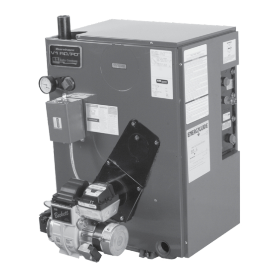
- Page 1 INSTALLATION, OPERATING AND SERVICE INSTRUCTIONS FOR V1™ RO/FO SERIES OIL - FIRED BOILER For service or repairs to boiler, call your heating contractor or oil supplier. When seeking information on boiler, provide Boiler Model Number and Serial Number as shown on Rating Label located on top of the boiler. Boiler Model Number Boiler Serial Number Installation Date...
- Page 2 IMPORTANT INFORMATION - READ CAREFULLY All boilers must be installed in accordance with National, State and Local Plumbing, Heating and Electrical Codes and the regulations of the serving utilities. These Codes and Regulations may differ from this instruction manual. Authorities having jurisdiction should be consulted before installations are made.
- Page 3 DANGER DO NOT store or use gasoline or other flammable vapors or liquids in the vicinity of this or any other appliance. WARNING Improper installation, adjustment, alteration, service or maintenance can cause property damage, personal injury or loss of life. Failure to follow all instructions in the proper order can cause personal injury or death.
-
Page 4: Table Of Contents
WARNING This boiler contains very hot water under high pressure. DO NOT unscrew any pipe fittings nor attempt to disconnect any components of this boiler without positively assuring the water is cool and has no pressure. Always wear protective clothing and equipment when installing, starting up or servicing this boiler to prevent scald injuries. -
Page 7: Ii. Pre-Installation
SECTION II: PRE-INSTALLATION an unconfined space. If the result is less than 50 ft /1000 INSPECT SHIPMENT carefully for any signs of BTU per hour then the space is considered a confined damage. space. 1. ALL EQUIPMENT is carefully manufactured, 4. -
Page 8: Iii. Installation Instructions
III: INSTALLATION INSTRUCTIONS 2. Tilt boiler to right and to rear. Using right rear leg REMOVE CRATE - as pivot, rotate boiler 90° in a clockwise direction, 1. Remove all fasteners at crate skid. and lower left side of boiler to floor. Tilt boiler 2. - Page 9 III: INSTALLATION INSTRUCTIONS (continued) 3. Check that cerafelt gasket is in place on top of the 3. Securing Limit Sensor, see Figure 5. cast iron block. Step a. Bend the Limit Sensor lead wires over front 4. Using screwdriver and pliers, remove the 6½" knock edge of Immersion Well making sure that sensor out from the rear panel, AS SHOWN IN Figure 3, is still fully seated.
- Page 10 5. If the boiler is to be operated in a system which has Problems caused by oxygen contamination of boiler a large volume or excessive radiation where low water are not covered by U.S. Boiler Company's boiler water temperatures may be encountered (i.e. standard warranty.
- Page 11 III: INSTALLATION INSTRUCTIONS (continued) Figure 8: Recommended Piping for Combination Heating & Cooling (Refrigeration) System Figure 7: Recommended Bypass Piping for V1 RO/FO safe water level of a hot water boiler is just above the highest water containing cavity of the boiler; that is, a Remove the circulator and install a pipe tee between hot water boiler must be full of water to operate safely.
- Page 12 Pressure Drop Boiler Model tees in which the hose bibs are located should be the (GPM) Thru Heater (PSI) same size as heater connections to minimize pressure V13A RO/FO V1-2 3¼ drop. V14A RO/FO V1-2 4. HARD WATER - This applicable to some city water and particularly to well water.
-
Page 13: Iv. Venting (Natural Vent - Chimney)
IV: VENTING (NATURAL VENT - CHIMNEY) INSTALL BREECHING. For normal installation in Furthermore, the likelihood of accidental ignition of a large confined space refer to local codes for proper combustibles within 12" of the breeching is increased selection of the breeching materials. when the boiler is installed in a confined space. - Page 14 IV: VENTING (NATURAL VENT - CHIMNEY) (continued) Figure 12: Installation of RO in a Confined Space with Adjacent Chimney NOTE: 1. Type L Vent Material generally means stainless steel inner liner and stainless steel outer covering and separated with 1" thick special high temperature insulation - factory assembled and rated.
- Page 15 IV: VENTING (NATURAL VENT - CHIMNEY) (continued) Figure 13: Installation of FO in a Confined Space with Remote Chimney NOTE: 1. Type L Vent Material generally means stainless steel inner liner and stainless steel outer covering and separated with 1" thick special high temperature insulation - factory assembled and rated.
- Page 16 IV: VENTING (NATURAL VENT - CHIMNEY) (continued) 1. INSTALL DRAFT REGULATOR following instructions furnished with Regulator. See Figure 2. Consider the chimney overall. Chimneys that have a high heat loss may become less suitable as the heat loss of the home goes down and the efficiency of the boiler installed goes up.
-
Page 17: V. Electrical
V: ELECTRICAL DANGER Positively assure all electrical connections are unpowered before attempting installation or service of electrical components or connections of the boiler or building. Lock out all electrical boxes with padlock once power is turned off. WARNING Failure to properly wire electrical connections to the boiler may result in serious physical harm. Electrical power may be from more than one source. - Page 19 V: ELECTRICAL (continued) NOTE: APPLY THIS BURNER SCHEMATIC TO APPROPRIATE STEAM OR WATER BOILER CONTROL SCHEMATIC, REFER TO FIGURE 15 Figure 16: Schematic Wiring Diagrams For Beckett GeniSys Oil Primary Control...
-
Page 20: Vi. System Start-Up
VI: SYSTEM START-UP h. When zone valve is completely purged of air, ALWAYS INSPECT INSTALLATION BEFORE close zone valve or shut-off valve. Open zone STARTING BURNER. valve to the next zone to be purged. Repeat 1. Verify that the venting, water piping, oil piping, and this step until all zones have been purged. - Page 21 VI: SYSTEM START-UP (continued) 4. CHECKOUT end of the air tube. This distance for L1 & L2 heads is 1-3/8" if the tube has a straight shroud Put the system into operation and observe at least or 1-3/4" if the air tube has a conic shroud. one complete cycle to make sure that the controller operates properly.
- Page 22 VI: SYSTEM START-UP (continued) Figure 17: "L1" Fixed Head Electrode Positioning and Gun Setting (Beckett AFG) Figure 18: "F" Fixed Head Electrode Positioning and Gun Setting (Beckett AFG)
- Page 23 VI: SYSTEM START-UP (continued) d. Turn "OFF" the burner. Remove the pressure START OIL BURNER. gauge and install port/bleeder plug and/or 1. Open vent fitting on fuel pump. reconnect the nozzle port line and tighten. Start 2. PRESS RED RESET BUTTON on primary control, the burner again.
- Page 24 VI: SYSTEM START-UP (continued) failure re-occurs, call your heating contractor WARNING immediately before pressing the reset button. Before installation of the boiler is considered WARNING complete, the operation of all boiler controls must be checked, particularly the primary control and DO NOT attempt to start the burner when excess high limit control.
- Page 25 VI: SYSTEM START-UP (continued) transition the control to a dedicated 3. CHECK OIL PRIMARY CONTROL Pump Prime mode, during which the CAUTION motor, igniter, and valve are powered for four (4) minutes. The yellow light will be Due to the potential hazard of line voltage, only a trained, experienced service technician should •...
- Page 26 VI: SYSTEM START-UP (continued) • c. Allow the temperature to drop below control After third Recycle Mode trial, safety setting. The burner must restart. switch locks out within safety switch timing indicated on label and control d. Boiler installation is not considered complete enters Restricted Mode.
-
Page 27: Vii. Operating
VII: OPERATING WATER BOILERS SEQUENCE OF OPERATION d. If the thermostat is not satisfied and the Operating Setpoint (SP) is reached the system 1. Water Boilers with Tankless Heaters (Warm circulator will continue to operate and the burner Start), Sequence Of Operation: will stop. - Page 28 VII: OPERATING (continued) “I” Press and release the key on the Boiler Control Warm Start Boiler Control to change from one parameter to the next. Each Adjustment Mode Options setting will alternately flash between the relevant 140-240°F Adjust High Limit Setting display code and its corresponding value.
- Page 29 VII: OPERATING (continued) Setpoint of 10°F. The Low Limit Differential g. Start Temperature (t_) is the number of degrees the boiler temperature The amount of “Heat available” is calculated by must decrease below the Low Limit Setpoint taking the difference between measured boiler before the Warm Start Boiler Control takes water temperature and the Start Temperature actions to warm the boiler.
- Page 30 VII: OPERATING (continued) forced off for a DHW call for heat. Refer to Table 8: Zone Request, Parameter zc_= zr Table 7A. Call for Heat Circulator Status When an Outdoor Air Reset Option Card is installed and there is a DHW call for heat Input Input Output...
- Page 31 Gallons Per Gallons Per Model No. o. Refill the system with fresh water. Month Year V13A RO/FO 0.27 3. Add appropriate boiler water treatment compounds as recommended by your qualified water treatment V14A RO/FO 0.32 company.
- Page 32 VIII: MAINTENANCE AND SERVICE INSTRUCTIONS (continued) 3. Always keep the manual fuel supply valve shut off ATTENTION TO BOILER WHILE NOT IN if the burner is shut down for an extended period of OPERATION time. NOTICE 4. To recondition the heating system in the fall season after a prolonged shut down, follow the instructions If boiler is not used during winter time, it must be outlined in Section VI, System Start-Up, Paragraphs...
-
Page 33: Ix. Cleaning Of Boiler
IX: CLEANING OF BOILER 2. Using wire or fibre bristle brush and vacuum, clean TO CLEAN FLUEWAYS top of boiler through flue collar of canopy. 1. Free Control Capillary Tubing, see Figure 1. Remove screws from plastic clips securing capillary REASSEMBLY OF PARTS to jacket. - Page 34 Important Product Safety Information Refractory Ceramic Fiber Product Warning: The Repair Parts list designates parts that contain refractory ceramic fibers (RCF). RCF has been classified as a possible human carcinogen. When exposed to temperatures about 1805°F, such as during direct flame contact, RCF changes into crystalline silica, a known carcinogen.
-
Page 35: X. Troubleshooting
X: TROUBLESHOOTING 6. WATER — Water in the fuel in large amounts will COMBUSTION stall the fuel pump. Water in the fuel in smaller 1. NOZZLES — Although the nozzle is a relatively amounts will cause excessive wear on the pump, inexpensive device, its function is critical to the but more importantly water doesn’t burn. - Page 36 X: TROUBLESHOOTING (continued) f. CAD cell defective. OIL PRIMARY CONTROL (Oil Primary) 1. Burner (Oil Primary) will not come on. g. Oil valve stuck open or closed. a. No power to Oil Primary. Note: The Safety Monitoring Circuit (SMC) is b.
- Page 37 X: TROUBLESHOOTING (continued) b. If the Boiler Control detects an error it will flash "Err" (boiler control error) followed by a number. Use this text and number to identify the boiler problem and corrective action in Table 11 below. Table 11: Boiler Control Error Numbers Display Status Recommended Corrective Actions...
-
Page 38: Xi. Repair Parts
Series Repair Parts may be obtained through your local U.S. Boiler Company Wholesale All V1™ RO/FO distributor. Should you require assistance in locating a U.S. Boiler Company Distributor in your area, or have questions regarding the availability of U.S. Boiler Company products or repair parts, please contact... - Page 39 XI: REPAIR PARTS (continued) BARE BOILER ASSEMBLY RO/FO Boiler Size/Quantity Description Part Number V13A V14A V13(A) Rear Outlet Canopy Carton w/Mounting 611220351 Hardware V14(A) Rear Outlet Canopy Carton w/Mounting 611220451 Hardware V13(A) Front Outlet Canopy Carton w/Mounting 61122034 Hardware V14(A) Front Outlet Canopy Carton w/Mounting 61122044 Hardware 6172203...
- Page 41 XI: REPAIR PARTS (continued) FLUSH JACKET COMPONENTS RO/FO Boiler Size/Quantity Key No. Description Part Number V13A V14A 60422035 Complete Flush Jacket Assembly - Complete with Key Item Nos. 2 thru 5 60422045 60422032 Jacket Left Side Panel Assembly 60422042 60422034 Jacket RO/FO Top &...
- Page 43 XI: REPAIR PARTS (continued) TRIM AND CONTROLS RO/FO Boiler Size/Quantity Description Part Number V13A V14A Trim / Control Group L7224A1038 Warm Start Aquastat 104389-01 Oil Primary Control, Beckett GeniSys 7505B 103447-01 Temperature / Pressure Gauge, 2-1/2" Dia. 100282-01 Honeywell 123870 A/T Well, 3/4" NPT x 1-1/2 80160426 Miscellaneous Parts Carton Group Taco 007F Position 4 Circulator...
- Page 45 NOTE: When ordering parts always give the serial and model numbers shown on the boiler and burner. Also provide the name of the part(s) and part number as listed below. Boiler Model V13A RO/FO V14A RO/FO Air Tube Combination AFG70MMAQN AF53ZP Beckett's Spec No.
-
Page 46: Appendix A
APPENDIX A: LOW WATER CUT OFF (LWCO) ON HOT WATER BOILERS WARNING DO NOT ATTEMPT to cut factory wires to install an aftermarket Low Water Cut Off (LWCO). Only use connections specifically identified for Low Water Cut Off. In all cases, follow the Low Water Cut Off (LWCO) manufacturer's instructions. minimum When connection must have a... - Page 47 APPENDIX A: LOW WATER CUT OFF (LWCO) ON HOT WATER BOILERS (continued) How to Test valve and relief valve once completed. Generate a Shut off fuel supply. Close shut-off valves in system boiler demand by turning up thermostat. Boiler should supply and return piping located in near boiler piping not attempt to operate.
- Page 48 U.S. Boiler Company, Inc. P.O. Box 3020 Lancaster, PA 17604 1-888-432-8887 www.usboiler.net...
Need help?
Do you have a question about the V13A RO/FO and is the answer not in the manual?
Questions and answers