U.S. Boiler Company MegaSteam MST288 Installation, Operating And Service Instructions
Hide thumbs
Also See for MegaSteam MST288:
Table of Contents
Advertisement
Quick Links
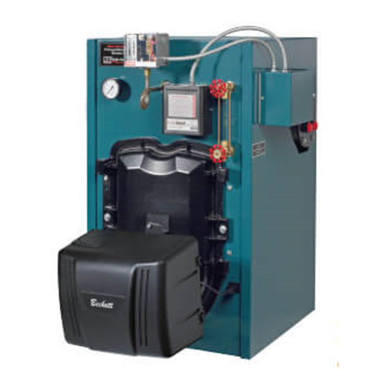
Installation, Operating and Service Instructions for
MegaSteam
Residential
9700609
TO THE INSTALLER:
Affix these instructions adjacent to boiler.
TO THE CONSUMER:
Retain these instructions for future reference.
For service or repairs to boiler, call your heating contractor. When seeking information on boiler, provide
Boiler Model Number and Serial Number as shown on Rating Label.
WARNING
Improper installation, adjustment, alteration, service or maintenance can cause
property damage, injury, or loss of life. For assistance or additional information, consult a qualified
installer, service agency or the gas supplier. This boiler requires a special venting system. Read these
instructions carefully before installing.
103536-08 - 4/18
TM
Natural Draft
Oil-Fired
Steam Boiler
Price - $5.00
Advertisement
Table of Contents

Subscribe to Our Youtube Channel
Related Manuals for U.S. Boiler Company MegaSteam MST288


Summary of Contents for U.S. Boiler Company MegaSteam MST288
- Page 1 Installation, Operating and Service Instructions for MegaSteam Residential Natural Draft Oil-Fired Steam Boiler 9700609 TO THE INSTALLER: Affix these instructions adjacent to boiler. TO THE CONSUMER: Retain these instructions for future reference. For service or repairs to boiler, call your heating contractor. When seeking information on boiler, provide Boiler Model Number and Serial Number as shown on Rating Label.
- Page 2 IMPORTANT INFORMATION - READ CAREFULLY All boilers must be installed in accordance with National, State and Local Plumb- ing, Heating and Electrical Codes and the regulations of the serving utilities. These Codes and Regulations may differ from this instruction manual. Authorities having jurisdiction should be consulted before installations are made.
- Page 3 DANGER DO NOT store or use gasoline or other flammable vapors or liquids in the vicinity of this or any other appliance. WARNING Improper installation, adjustment, alteration, service or maintenance can cause property damage, personal injury or loss of life. Failure to follow all instructions in the proper order can cause personal injury or death.
-
Page 4: Table Of Contents
WARNING This boiler contains very hot water under high pressure. Do not unscrew any pipe fittings nor attempt to disconnect any components of this boiler without positively assuring the water is cool and has no pressure. Always wear protective clothing and equipment when installing, starting up or servicing this boiler to prevent scald injuries. - Page 5 103536-08 - 4/18...
- Page 6 Table 1A: Dimensional (Data See Figure 1) Water Content Heat Minimum Chimney Actual Dimensions (See Figure 1) (To Normal Water Boiler Transfer Requirements Shipping Line) - Gallons Model Surface Weight Area - sq. With Tankless Round Rectangle Height (LB.) "A" "B"...
-
Page 7: Pre-Installation
Section I: Pre-Installation A. INSPECT SHIPMENT carefully for any signs of • 30" for flueway cleaning (MST513) damage. • 36" for flueway cleaning (MST629) b. Clearance from Jacket Left Side Panel - 1. All equipment is carefully manufactured, inspected and packed. Our responsibility •... - Page 8 Section I: Pre-Installation (continued) 5. For minimum clearances to combustible Accessory Kit Instructions for installation materials. See Figure 2. and air intake piping details. NOTICE Clearance to venting is for single wall vent pipe. If Type L vent is used, clearance b.
-
Page 9: Unit-Pak Boiler Assembly
Section II: Unit-Pak Boiler Assembly MegaSteam™ Unit-Pak Boiler Assembly Shipment Content Check List (see Figure 3) 1. ___ Cast Iron Section/Burner Swing Door/Smoke Box Assembly Mounted on Shipping Skid: ____ MST3 (Rear Section, Heater) – Part # 100566-03 / 102417-01 / 100021-01 ____ MST4 (Rear Section, Heater) –... - Page 10 Section II: Unit-Pak Boiler Assembly (continued) A. CAST IRON SECTION ASSEMBLY TAPPINGS 6. For manual Cast Iron Section/Burner Swing Door/Smoke Box Assembly removal prepare Refer to Table 3 "Purpose of Tappings and one piece of 4” x 4” x 16” lg. (or two pieces of Bosses"...
- Page 11 Section II: Unit-Pak Boiler Assembly (continued) 103536-08 - 4/18...
- Page 12 Section II: Unit-Pak Boiler Assembly (continued) See also Figure 7 “Purpose of Tappings & D. JACKET FRONT PANEL INSTALLATION. Bosses”. In order to install front jacket panel Burner Swing Door and door mounting bracket need to be 2. Open Jacket Carton and locate jacket front removed.
- Page 13 Section II: Unit-Pak Boiler Assembly (continued) if the rope is damaged, or, there is a gap By design, door insulation on model MST629 between the rope ends. will have two by-pass pockets cast into the 10. Inspect burner swing door insulation for insulation centered on the bar between the damage and proper type.
- Page 14 Section II: Unit-Pak Boiler Assembly (continued) 11. Upon inspection completion, lift door and place NOTE: Read caution statement before integral cast hinge pins into door mounting proceeding. bracket slotted holes. Do not close and secure CAUTION These baffles will generate door at this time, proceed to installing stainless higher efficiencies and lower stack steel flueway baffles.
- Page 15 Section II: Unit-Pak Boiler Assembly (continued) tightening the hardware as far as possible and then release the pressure. NOTICE When securing burner swing door make sure door is drawn-in equally on both sides. d. Use a hand or socket wrench to tighten door hardware.
- Page 16 Section II: Unit-Pak Boiler Assembly (continued) Figure 7: Purpose of Tappings and Bosses Table 3: Purpose Of Tapping & Bosses Steam Boiler Tapping Boss Thread Size Size, NPT Location Location Less Heater With Heater ¼" - 18 Pressure Gauge ¼" - 18 Pressure Limit ¾"...
- Page 17 Section II: Unit-Pak Boiler Assembly (continued) 8. Align upper panel attachment holes with 2. Carefully cut the plastic bag and remove smokebox upper attachment bosses and Insulation Wrapper. The wrapper will expand install 5/16”-18 x ½” Phillips pan head machine upon removal.
- Page 18 Section II: Unit-Pak Boiler Assembly (continued) L. TRIM AND CONTROLS INSTALLATION. over four #8 x ½” shoulder sheet metal screws, previously installed at Front and Rear Jacket Pressure Limit Installation. Panel side flanges, so teardrop cutouts in 1. Locate and remove L404F Pressure Limit with the side panel inside flanges engage all four factory attached harness from Control Carton.
- Page 19 Section II: Unit-Pak Boiler Assembly (continued) 3. Slip the bulb of the aquastat controller into the M. PROBE LWCO (HYDROLEVEL CG450, well and secure the controller in place with the OR, MCDONNELL-MILLER PSE801-120) set screw. INSTALLATION. WARNING 1. Remove either Hydrolevel CG450 LWCO with Aquastat bulb must be fully factory attached harness and Hydrolevel probe inserted into the well.
- Page 20 Section II: Unit-Pak Boiler Assembly (continued) Figure 9: Oil Burner Installation (Beckett Burner Shown) 5. Thread 1-1/2" NPT x 5” lg. black nipple into e. Insert oil burner into the opening of burner lower rear section tapping, then, install 1-1/2” swing door.
-
Page 21: Steam Boiler Piping & Trim
Oxygen contamination of boiler water will cause corrosion of iron and steel boiler components, and can lead to boiler failure. U.S. Boiler Company's Standard Warranty does not cover problems caused by oxygen contamination of boiler water or scale (lime) build-up caused by frequent addition of water. - Page 22 Section III: Steam Boiler Piping & Trim (continued) 103536-08 - 4/18...
- Page 23 Section III: Steam Boiler Piping & Trim (continued) Table 4: Material Provided for Boiler Models MST288, MST396 and MST513 Item Fittings Part Number Quantity 2” x 12” Nipple 806600330 2” Union 806604019 2” x 6” Nipple 806600204 2” Elbow 806601538 2”...
- Page 24 Section III: Steam Boiler Piping & Trim (continued) Table 5: Material Provided for Boiler Model MST629 Item Fittings Part Number Quantity 2” x 12” Nipple 806600330 2” Union 806604019 2” x 6” Nipple 806600204 2” Elbow 806601538 2” x 15” Nipple 101435-01 3”...
- Page 25 Section III: Steam Boiler Piping & Trim (continued) Table 6: Dropped Header Material Provided for Boiler Models MST288, MST396 and MST513 Item Fittings Part Number Quantity 2” x 12” Nipple 806600330 2” Union 806604019 2” x 6” Nipple 806600204 2” Elbow 806601538 2”...
- Page 26 Section III: Steam Boiler Piping & Trim (continued) Table 7: Dropped Header Material Provided for Boiler Model MST629 Item Fittings Part Number Quantity 2” x 12” Nipple 806600330 2” Union 806604019 2” x 6” Nipple 806600204 2” Elbow 806601538 2” x 15” Nipple 101435-01 2”...
-
Page 27: Tankless & Indirect Water Heater Piping
Section IV: Tankless & Indirect Water Heater Piping A. CONNECT TANKLESS HEATER PIPING as dishwashers and automatic washers is shown in Figure 15. See Table 8 for Tankless possible by piping the hot water from the Heater Rating. heater prior to entering the mixing valve. The mixing valve should be “trapped”... - Page 28 Section IV: Tankless & Indirect Water Heater Piping (continued) Figure 15: Schematic Tankless Water Heater Piping Table 8: Tankless Heater Data Heater Rating Pressure Drop thru Boiler Model Heater No. (GPM) Heater (PSI) MST288 3.00 18.7 MST396 3.50 25.4 222B MST513 3.75 32.7...
- Page 29 Section IV: Tankless & Indirect Water Heater Piping (continued) Figure 16: Alliance SL™ Water Heater Piping with MegaSteam™ Boiler B. CONNECT ALLIANCE SL™ INDIRECT WATER 1. Refer to Alliance SL™ manual for additional HEATER PIPING as shown in Figure 16. information.
-
Page 30: Venting & Air Intake Piping
Section V: Venting & Air Intake Piping WARNING Vent this boiler according to these instructions. Failure to do so may cause products of combustion to enter the home resulting in severe property damage, personal injury or death. Insufficient Combustion Air Supply may result in the production and release of deadly carbon monoxide •... - Page 31 Section V: Venting & Air Intake Piping (continued) Figure 17: Recommended Vent Pipe Arrangement and Chimney Requirements Figure 18: Proper and Improper Locations of Draft Regulator 103536-08 - 4/18...
- Page 32 Section V: Venting & Air Intake Piping (continued) c. Abandoned Openings – Openings through C. DRAFT the chimney wall that are no longer used 1. The natural draft generated through a chimney is shall be sealed in accordance to NFPA 211. dependent on several factors including, chimney Often abandoned openings are improperly height, temperature of flue gases, cross section...
- Page 33 Section V: Venting & Air Intake Piping (continued) the greater the amount of draft that can be WARNING Remove the baffles if there generated. A lower stack temperature not only are any signs of condensation in the chimney reduces the amount of draft that can be created or chimney connector.
-
Page 34: Electrical
Section VI: Electrical DANGER Positively assure all electrical connections are unpowered before attempting installation or service of electrical components or connections of the boiler or building. Lock out all electrical boxes with padlock once power is turned off. WARNING Failure to properly wire electrical connections to the boiler may result in serious physical harm. - Page 35 Section VI: Electrical (continued) 103536-08 - 4/18...
- Page 36 Section VI: Electrical (continued) 103536-08 - 4/18...
- Page 37 Section VI: Electrical (continued) 103536-08 - 4/18...
- Page 38 Section VI: Electrical (continued) BOILER SEQUENCE OF OPERATION WITH PROBE LWCO (See Figure 20) When the thermostat calls for heat, it energizes the R8285C Control Center relay which in turn energizes the cad cell primary control, bringing on the burner. The burner will operate in the following sequence: Prepurge for the first 10 seconds;...
-
Page 39: Oil Piping
Section VII: Oil Piping A. GENERAL WARNING Under no circumstances can 1. Use flexible oil line(s) so the burner swing door copper with sweat style connectors be used. can be opened without disconnecting the oil NOTICE Some jurisdictions require the use of supply piping. - Page 40 Section VII: Oil Piping (continued) C. TWO PIPE OIL LINES 3. Under no circumstances is a manual shutoff valve to be located on the return line of a two 1. For two piped systems, where more lift pipe system. Accidental closure of the return is required, the two-stage fuel unit is line will rupture the oil pump seals.
-
Page 41: System Start-Up
Section VIII: System Start-Up WARNING All boilers equipped with burner swing door have a potential hazard which can cause severe property damage, personal injury or loss of life if ignored. Before opening swing door, turn off service switch to boiler to prevent accidental firing of burner outside the combustion chamber. Be sure to tighten swing door fastener completely when service is completed. - Page 42 Section VIII: System Start-Up (continued) 5. Adjust oil pressure. water column ("w.c.) (water gauge) in canopy. These settings will assure a safe and efficient a. When checking a fuel unit's operating operating condition. If the flame appears pressure, a reliable pressure gauge may stringy instead of a solid fire, try another be installed in either the bleeder port or the nozzle of the same type.
- Page 43 Section VIII: System Start-Up (continued) CHECK THERMOSTAT OPERATION. d. Limited Reset (Restricted Mode): In order to limit the accumulation of unburned oil Raise and lower thermostat setting as required to in the combustion area, the control can start and stop burner. only be reset three times.
- Page 44 Section VIII: System Start-Up (continued) c. Simulate Ignition or Flame Failure: • Close line switch to boiler. If burner • starts and runs beyond safety switch Follow procedure to turn on burner. cut-off time, cell is good. If not, install •...
- Page 45 Section VIII: System Start-Up (continued) Important Product Safety Information Refractory Ceramic Fiber Product WARNING The Service Parts list designates parts that contain refractory ceramic fibers (RCF). RCF has been classified as a possible human carcinogen. When exposed to temperatures above 1805°F, such as during direct flame contact, RCF changes into crystalline silica, a known carcinogen.
-
Page 46: Maintenance & Service Instructions
Section IX: Maintenance and Service Instructions i. Apply a moderate amount of good quality A. MAINTENANCE OF LOW WATER CUT-OFF pipe dope to the pipe threads on the probe, DEVICES leaving the two end threads bare. Do not use PTFE (Teflon) tape. WARNING Probe and float type low j. - Page 47 Section IX: Maintenance and Service Instructions (continued) iii. Turn on oil burner and keep operating NOTICE Check with local authorities or while feeding water to boiler slowly. This consult local water treatment services for will raise water level in boiler slowly so acceptable chemical cleaning compounds.
- Page 48 Section IX: Maintenance and Service Instructions (continued) e. Make pH or Alkalinity Test. happens the cast iron in that area gets extremely hot and eventually cracks. The presence of free After boiler and system have been cleaned oxygen or chloride salts in the boiler corrodes and refilled as previously described, test the cast iron from the inside.
-
Page 49: Boiler Cleaning
Section X: Boiler Cleaning WARNING All boiler cleaning must be completed with burner service switch turned off. Boilers equipped with burner swing door have a potential hazard which can cause severe property damage, personal injury or loss of life if ignored. Before opening swing door, turn off service switch to boiler to prevent accidental firing of burner outside the combustion chamber. - Page 50 Section X: Boiler Cleaning (continued) Figure 28: Cleaning Boiler Flueways and Combustion Chamber Surfaces WARNING The boiler must be connected to an approved chimney in good condition. Serious property damage could result if the boiler is connected to a dirty or inadequate chimney. The interior of the chimney flue must be inspected and cleaned before the start of the heating season and should be inspected periodically throughout the heating season for any obstructions.
-
Page 51: Troubleshooting
Section XI: Trouble Shooting A. COMBUSTION 7. WATER — Water in the fuel in large amounts will stall the fuel pump. Water in the fuel in 1. NOZZLES — Although the nozzle is a smaller amounts will cause excessive wear on relatively inexpensive device, its function is the pump, but more importantly water doesn’t critical to the successful operation of the oil... - Page 52 Section XI: Trouble Shooting (continued) c. CAD cell seeing light. d. Airflow too high. d. CAD assembly defective. e. Ignitor module defective. e. Control motor relay is stuck closed (see f. CAD cell defective. note below). g. Oil valve stuck open or closed. 2.
-
Page 53: Repair Parts
All MegaSteam™ Boiler Repair Parts may be obtained through your local U.S. Boiler Company Wholesale distributor. Should you require assistance in locating a U.S. Boiler Company Distributor in your area, or have questions regarding the availability of U.S. Boiler Company products or repair parts, please contact U.S. Boiler Company Customer Service at (717) 481-8400 or Fax (717) 481-8408. - Page 54 Section XII: Repair Parts (continued) 103536-08 - 4/18...
- Page 55 Section XII: Repair Parts (continued) Item Description Part No. MST288 MST396 MST513 MST629 1. BARE BOILER ASSEMBLY Cast Iron Block Assembly - 3 Section (Heater) 100566-03 Cast Iron Block Assembly - 4 Section (Heater) 100566-04 Cast Iron Block Assembly - 5 Section (Heater) 100566-05 Spanner Bar w/Threaded Inserts, 100012-02...
- Page 56 Section XII: Repair Parts (continued) 103536-08 - 4/18...
- Page 57 Section XII: Repair Parts (continued) Item Description Part No. MST288 MST396 MST513 MST629 1. BARE BOILER ASSEMBLY (Continued) Cap Screw, 5/16" -18 x 3/4" Lg., Plated 80861340 1/4" NPT Pipe Plug, Square Head, Brass 806603542 6" Dia. 100093-01 Smokebox Collar 7"...
- Page 58 Section XII: Repair Parts (continued) 103536-08 - 4/18...
- Page 59 Section XII: Repair Parts (continued) Item Description Part No. MST288 MST396 MST513 MST629 2. JACKET ASSEMBLY Jacket Front Panel Assembly w/Insulation 100575-01 Power Outlet Receptacle, w/Harness 100605-01 #8 x 1/2" Type AB Truss Head w/Shoulder, Sheet Metal 100038-01 Screw, Plated Jacket Rear Panel Assembly w/Insulation 100578-01 External Wiring Enclosure...
- Page 60 Section XII: Repair Parts (continued) 103536-08 - 4/18...
- Page 61 Section XII: Repair Parts (continued) Item Description Part No. MST288 MST396 MST513 MST629 3. MST - TRIM AND CONTROLS 6" RC-STD Draft Regulator 8116288 7" RC-STD Draft Regulator 8116289 Pressure Gauge 100325-01 Probe, Hydrolevel EL-1214 (for Hydrolevel CG450) 80160629 Low Water Cut-off, Hydrolevel CG450 (less Probe) 107293-01 Low Water Cut-off, McDonnell &...
- Page 62 Section XII: Repair Parts (continued) 103536-08 - 4/18...
- Page 63 Section XII: Repair Parts (continued) BECKETT OIL BURNER PART NOS. FOR MEGASTEAM™ SERIES BOILERS NOTE: When ordering parts always give the serial and model numbers shown on the boiler and burner. Also provide the name of the part(s) and part number as listed below. Boiler Model MST288 MST396...
- Page 64 Section XII: Repair Parts (continued) Table 11: Beckett AFG Burner Specifications Approx. Baffles Baffles Baffles Baffles Stack Approx. Burner Head Pump Baffle Temp. Boiler Air Band Shipped Minimum Minimum Minimum Minimum Input Type Shutter Nozzle Pressure Location Increase Model (setting) Breech Breech Overfire...
- Page 65 103536-08 - 4/18...
- Page 66 103536-08 - 4/18...
- Page 67 103536-08 - 4/18...
- Page 68 U.S. Boiler Company, Inc. P.O. Box 3020 Lancaster, PA 17604 1-888-432-8887 www.usboiler.net 103536-08 - 4/18...
Need help?
Do you have a question about the MegaSteam MST288 and is the answer not in the manual?
Questions and answers