Table of Contents
Advertisement
N I
S
T
S
E
R
As an
ENERGY
STAR
®
Partner,
U.S. Boiler Company
has determined that the
V8H3S, V8H3W, V8H4S,
V8H4W, V8H5S, V8H5W,
V8H6S, V8H6W and V8H7
meet the ENERGY STAR
guidelines for Energy
United States Environmental
F
r o
s
e
v r
c i
e
r o
e r
p
i a
i
f n
r o
m
t a
o i
n
o
n
b
i o
e l
L
a
b
l e
o l
c
a
e t
d
o
n
o t
B
o
l i
r e
M
o
d
l e
N
u
m
b
V
8
H
H
e
t a
n i
g
C
o
t n
a r
t c
r o
A
d
d
e r
s
s
103869-02 - 10/12
A
L
L
A
I T
O
V
C I
E
N I
V
8
H
™
O
L I
-
I F
®
s r
o t
b
i o
e l
, r
c
a
l l
o y
r u
, r
p
o r
v
d i
e
B
o
l i
r e
M
o
p
f o
h t
e
b
i o
e l
. r
r e
B
o
l i
r e
S
N
,
O
P
E
R
S
T
R
U
C
I T
S
E
R
R
E
D
B
O
h
e
t a
n i
g
c
o
t n
a r
t c
r o
d
l e
N
u
m
b
r e
a
n
d
S
e
i r
e
i r
l a
N
u
m
b
r e
A
T
N I
G
A
O
N
S
F
O
E I
S
L I
E
R
r o
o
l i
s
u
p
l p
e i
. r
W
h
e
l a
N
u
m
b
r e
a
s
s
h
o
w
n I
s
a t
l l
t a
o i
n
D
a
e t
P
h
o
n
e
N
u
m
b
r e
N
D
R
9700609
n
s
e
e
k
n i
g
n
o
n
R
t a
n i
g
Price - $5.00
Advertisement
Table of Contents

Related Manuals for U.S. Boiler Company V8H5


Summary of Contents for U.S. Boiler Company V8H5
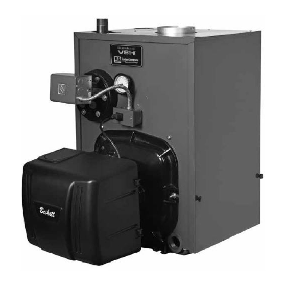
- Page 1 ™ As an ENERGY STAR ® Partner, U.S. Boiler Company has determined that the V8H3S, V8H3W, V8H4S, V8H4W, V8H5S, V8H5W, V8H6S, V8H6W and V8H7 9700609 meet the ENERGY STAR ® guidelines for Energy United States Environmental Price - $5.00 103869-02 - 10/12...
- Page 2 IMPORTANT INFORMATION - READ CAREFULLY All boilers must be installed in accordance with National, State and Local Plumbing, Heating and Electrical Codes and the regulations of the serving utilities. These Codes and Regulations may differ from this instruction manual. Authorities having jurisdiction should be consulted before installations are made.
- Page 3 DANGER DO NOT WARNING Improper installation, adjustment, alteration, service or maintenance can cause property damage, personal injury or loss of life. Failure to follow all instructions in the proper order can cause personal injury or death. Read and understand all instructions, including all those contained in component manufacturers manuals which are provided with the boiler before installing, starting-up, operating, maintaining or servicing this boiler.
-
Page 4: Table Of Contents
WARNING This boiler contains very hot water under high pressure. DO NOT to disconnect any components of this boiler without positively assuring the water is cool and has no boiler to prevent scald injuries. DO NOT rely on the pressure and temperature gauges to determine the temperature and pressure of the boiler. -
Page 5: Product Description, Specification
"C" Steam Boiler Boiler Boiler Boiler V8H3 17-1/8" 9-1/8" 6" 10.3 12.8 15.88 V8H4 22-1/8" 11-5/8" 6" 12.4 15.7 22.92 V8H5 27-1/8" 14-1/8" 7" 14.6 18.5 29.96 V8H6 32-1/8" 16-5/8" 7" 16.7 21.4 37.00 V8H7 37-1/8" 19-1/8" 8" 18.8 24.2 44.04... -
Page 10: Pre-Installation
SECTION II: PRE-INSTALLATION A. INSPECT SHIPMENT damage. or from or the top of the of goods. B. LOCATE BOILER NOTICE Clearance to venting is for single wall vent pipe. If Type L vent is used, clearance may be manufacturer. Figure 2: Minimum Installation Clearances To Combustible Materials (Inches) - Page 11 SECTION II: PRE-INSTALLATION (continued) C. PROVIDE COMBUSTION AND VENTILATION AIR. WARNING be provided to assure proper combustion and to maintain safe ambient air temperatures. DO NOT install boiler where gasoline or other Direct communication with outdoors. hydrocarbons (i.e. bleaches, fabric softeners, etc.) are used or stored.
-
Page 12: Knockdown Boiler Assembly
SECTION III: KNOCKDOWN BOILER ASSEMBLY A. REMOVAL OF BARE BOILER FROM SKID G. INSTALL AND SECURE CANOPY Figure 3: Knockdown Boiler Removal from Skid B. MOVE BOILER TO PERMANENT POSITION Figure 4: Boiler Canopy Installation C. TEST BOILER FOR LEAKS heating system. - Page 13 SECTION III: KNOCKDOWN BOILER ASSEMBLY (continued) Figure 5: Boiler Tapping Locations and Usage (Knockdown Boilers Only) PURPOSE OF TAPPINGS Steam Boiler Water Boiler Tapping Size Location Front Heater Non-Heater w/Heater Non-Heater Rear Heater Pressure Limit (Probe LWCO) L7248 L7224 ¾" Flush Plug Plugged (Float LWCO) Boiler Control...
- Page 14 SECTION III: KNOCKDOWN BOILER ASSEMBLY (continued) Figure 6: Knockdown Boiler Jacket Assembly H. INSTALL TRIM. usage. thru V8H5, if only one supply riser is used. INSTALL BOILER JACKET. door remove hinge pin and set door aside. Remove...
- Page 15 SECTION III: KNOCKDOWN BOILER ASSEMBLY (continued) Figure 7: Oil Burner Installation (Beckett Burner Shown) Step 1. Step 2. Use one hand to help hold door in position opposite hand. Always install right side J. INSTALL BECKETT OIL BURNER. bolt) second. then release the pressure.
- Page 16 SECTION III: KNOCKDOWN BOILER ASSEMBLY (continued) NOTICE When securing burner swing door make sure door Step 3. Never settings. CAUTION DO NOT install burner without gasket. NOTICE The burner for knockdown boilers has a pre- installed nozzle for steam applications. For water boiler applications, refer to Paragraph 8 in this Section for installation instructions to change nozzles.
- Page 17 SECTION III: KNOCKDOWN BOILER ASSEMBLY (continued) manual. open the transformer. GPH. removal. the adaptor. this manual. deliver the proper amount of air for their shoulder on the adaptor. Then tighten the L. INSTALL CARLIN 102CRD OIL BURNER, 7 thru 9 Section open the transformer.
- Page 18 SECTION III: KNOCKDOWN BOILER ASSEMBLY (continued) passed through the opening in the left side of the housing. for initial settings. M. INSTALL RIELLO OIL BURNER. pump. Figure 7B: Installation/Removal of Figure 7A: Combustion Head Adjustment - 102CRD Burner Riello Drawer Assembly...
- Page 19 SECTION III: KNOCKDOWN BOILER ASSEMBLY (continued) adapter. DO NOT over Figure 7C: Riello Nozzle Replacement Figure 7D: Riello Turbulator Setting to operate on a single line system. To operate on a two-line installed. the rear of this manual for details.
- Page 20 SECTION III: KNOCKDOWN BOILER ASSEMBLY (continued) WARNING: DO NOT operate a single line system NOTE: are British Parallel Thread will damage adapter must gauge models. N. INSTALL TRIM AND CONTROLS WITH BECKETT BURNER. Water Boilers Only WARNING Safety valve discharge piping must be piped near NOT pipe in any area where freezing could occur.
- Page 21 SECTION III: KNOCKDOWN BOILER ASSEMBLY (continued) Figure 8: Limit Sensor Insertion NOTICE Lower rear section Tapping "H" is used for standard condensate return on steam boilers. WARNING Safety valve discharge piping must be piped near 21B. NOT pipe in any area where freezing could occur. DO NOT install any shut-off valves, plugs or caps.
- Page 22 SECTION III: KNOCKDOWN BOILER ASSEMBLY (continued) Figure 9: Float-Type Low Water Cut-Off and Figure 10: Pressure Limit Installation for Probe Pressure Limit Installation P. INSTALL TRIM AND CONTROLS WITH CARLIN BURNERS. Water boilers Only Steam Boilers Only Carlin Burner. DO NOT leveling.
- Page 23 SECTION III: KNOCKDOWN BOILER ASSEMBLY (continued) 23A, 23B, 24A or 24B. Note: DO NOT Q. INSTALL TRIM AND CONTROLS WITH RIELLO BURNER. Water Boilers Only terminals. Steam Boilers Only R. BURNERS SUPPLIED BY U.S. BOILER COMPANY Figure 11: Burner Disconnect Junction Box with Power Outlet Receptacle (Mated to Burners with Disconnect Harness)
-
Page 24: Packaged Boiler Assembly
SECTION III: KNOCKDOWN BOILER ASSEMBLY (continued) tapping. Control Center or Boiler Control into appropriate SECTION IV: PACKAGED BOILER ASSEMBLY A. REMOVE CRATE. CAUTION DO NOT drop boiler. DO NOT bump boiler jacket C. MOVE BOILER TO PERMANENT POSITION B. REMOVE BOILER FROM SKID. D. - Page 25 SECTION IV: PACKAGED BOILER ASSEMBLY (continued) Figure 13A: Partial Front View - Burner Swing Door Mounted to Boiler - Fully Closed and Secured Step 4. NOTICE When securing burner swing door make sure door Step 4. Use an alternating tightening method Step 1.
- Page 27 SECTION IV: PACKAGED BOILER ASSEMBLY (continued) WARNING F. INSTALL BECKETT OIL BURNER. Refer Safety valve discharge piping must be piped near NOT pipe in any area where freezing could occur. NOTICE DO NOT install any shut-off valves, plugs or caps. The burner for packaged boilers has a pre-installed K.
-
Page 28: Water Boiler Piping & Trim
WARNING System supply and return piping must be connected to correct boiler pipe. U.S. Boiler Company recommends sizing the (GPM) to allow a 20°F temperature differen- WARNING tial in the system. When sizing the system circulator, the pressure drop of all radiators,... - Page 29 SECTION V: WATER BOILER PIPING AND TRIM (continued) 6. If it is required to perform a long term pressure test of the hydronic system Figure 14: Recommended Piping for Combination Heating and Cooling (Refrigeration) System...
-
Page 32: Steam Boiler Piping & Trim
Oxygen contamination of boiler water will cause corrosion of iron and steel boiler components, and can lead to boiler failure. U.S. Boiler Company's Standard Warranty does not cover problems caused by A. EVALUATE THE EXISTING STEAM SYSTEM. - Page 34 SECTION VII: TANKLESS AND INDIRECT WATER HEATER PIPING A. CONNECT TANKLESS HEATER PIPING as WARNING Install automatic mixing valve at tankless heater outlet to avoid risk of burns or scalding due to maintain the mixing valve in accordance with the manufacturer's instructions.
- Page 35 Heater Boiler Heater Model (GPM) (GPM) (PSI) (PSI) Model V8H3 222A Steam Water Steam Water V8H4 222A V8H3 V1-2 2.75 V8H5 222A 30.5 V8H4 V1-2 3.25 V8H6 222A V8H5 V1-2 3.25 222A V8H6 V1-2 3.75 3.75 V8H7 V8H7 V1-2 3.75 222A 4.75...
- Page 36 SECTION VII: TANKLESS AND INDIRECT WATER HEATER PIPING (cont'd) Figure 17B: Indirect Domestic Water Heater Piping with V8H Steam Boiler B. CONNECT INDIRECT DOMESTIC WATER HEATER PIPING information.
-
Page 37: Venting & Air Intake Piping
SECTION VIII: VENTING AND AIR INTAKE PIPING A. GENERAL VENTING GUIDELINES in your area. draft at all times, to assure safe proper operation installation. B. OPTIONAL AIR INTAKE PIPING INSTALLATION (ONLY AVAILABLE ON BECKETT BURNERS, WARNING DO NOT reduce size of air intake pipe. Read, understand and follow combustion air instruction restrictions contained in the Pre- Installation Section of this manual. - Page 38 SECTION VIII: VENTING AND AIR INTAKE PIPING (continued) Figure 19: Proper and Improper Locations of Draft Regulator...
- Page 39 SECTION VIII: VENTING AND AIR INTAKE PIPING (continued) NOTICE Intake terminal must be at least 12 inches above grade plus snow accumulation. WARNING DO NOT locate air intake where petroleum distillates, CFC's, detergents, volatile vapors or any other chemicals are present. Severe boiler corrosion and failure will result.
-
Page 40: Electrical
SECTION IX: ELECTRICAL DANGER Positively assure all electrical connections are unpowered before attempting installation or service of electrical components or connections of the boiler or building. Lock out all electrical boxes with padlock once power is turned off. WARNING Failure to properly wire electrical connections to the boiler may result in serious physical harm. Electrical power may be from more than one source. - Page 48 SECTION IX: ELECTRICAL (continued) Figure 25: Schematic Wiring Diagrams For All Burner Options w/Various Oil Primary Controls...
-
Page 49: Oil Piping
SECTION X: OIL PIPING A. GENERAL WARNING Under no circumstances can copper with sweat piping. style connectors be used. NOTICE shutoff valve at the tank and/or the burner. In used. fusible electrical interlock with the burner circuit. NOTICE DO NOT B. - Page 50 SECTION X: OIL PIPING (continued) C. TWO PIPE OIL LINES TABLE 4: SINGLE-STAGE UNITS (3450 RPM) - TWO PIPE SYSTEMS Lift "H" Maximum Length of Tubing (See Fig. 25) "H" + "R" (See Figure 27) 3/8" OD 1/2" OD Tubing (3 GPH) Tubing (3 GPH) 100' TABLE 3: TWO-STAGE UNITS (3450 RPM) -...
-
Page 51: System Start-Up
SECTION XI: SYSTEM START-UP WARNING personal injury or loss of life if ignored. Before opening swing door, turn off service switch to boiler to completely when service is completed. A. ALWAYS INSPECT INSTALLATION BEFORE STARTING BURNER. WARNING Completely read, understand and follow all instructions in this manual before attempting start up. - Page 52 SECTION XI: SYSTEM START-UP (continued) 3. Carlin Elite EZ Burners 4. Carlin 102CRD Burners this manual. 5. Riello Burners rear of this manual. E. ADJUST OIL BURNER BEFORE STARTING. rear of this manual. rear of this manual. 2. Beckett Burners F.
- Page 53 SECTION XI: SYSTEM START-UP (continued) Carlin Elite EZ Burners for details. Carlin 102CRD Burners pressure should drop and hold. Riello Burners at the rear of this manual. running. Figure 28: Adjusting Fuel Pump Pressure G. ADJUST OIL BURNER WHILE OPERATING. of 11.5 room temperature.
- Page 55 SECTION XI: SYSTEM START-UP (continued) WARNING DO NOT attempt to start the burner when excess oil has accumulated, when the boiler is full of vapor, or when the combustion chamber is very hot. Figure 29B: Electrode Positioning, Retention Ring H. CHECK FOR CLEAN CUT OFF OF Assembly and Nozzle Adapter (Carlin EZ-1 / EZ-2) BURNER.
- Page 56 SECTION XI: SYSTEM START-UP (continued) up again. light turns on. " Note: DO NOT 21B, 22, 23A, 23B, 24A or 24B. This feature limits the Flame Detection Range Normal (0 - 1600 ohms) Limited (1600 ohms to lockout) Honeywell R7284 Control Features, Figure 30A: GeniSys 7505 Oil Primary Terminals, LED's and Reset Button...
- Page 57 SECTION XI: SYSTEM START-UP (continued) CAUTION Due to the potential hazard of line voltage, only a trained, experienced service technician should perform the following safety checks. DO NOT attempt to take it apart. Replace entire control if operation is not as described. Preliminary Steps supply.
- Page 58 SECTION XI: SYSTEM START-UP (continued) running. Figure 31: Cad Cell Location Close hand valve in oil supply line. J. IF CONTROLS MEET REQUIREMENT outlined . IF CONTROLS DO NOT MEET REQUIREMENTS WARNING Cad Cell Jumper must be removed after this check.
-
Page 59: Operating
SECTION XII: OPERATING A. WATER BOILERS SEQUENCE OF OPERATION Water Boilers Without Tankless Heaters as Status Codes on Cold Start Boiler Control Figure 32: Intelligent Oil Boiler Control 2. Water Boilers with Tankless Heaters as Status Codes on Warm Start Boiler Control TABLE 5: SEQUENCE OF OPERATION Status Codes Displayed in Mode... - Page 60 SECTION XII: OPERATING (CONTINUED) 4. Viewing the Operating Mode Options I” Press and release the Operating Mode Options Status Numbers: Standby Running Self Test) Boiler Temperature Operating Setpoint (Outdoor Reset) High Limit Setting for heat. High Limit Differential Low Limit Setpoint (warm start only) Low Limit Differential (warm start only) Heat Request Status DHW Request Status...
- Page 61 SECTION XII: OPERATING (CONTINUED) Cold Start Boiler Control Adjustment Mode Options 140-240°F Adjust High Limit Setting 10-30°F Adjust High Limit Differential ZC and ZR Terminal Function 0-10 minutes Pump Overrun Time 2-20 minutes Pump Pre-purge Time 140 - 180°F Start Temperature Priority Time Select degrees F or C Mode Back to Operating Mode...
- Page 62 SECTION XII: OPERATING (CONTINUED) TABLE 6: CIRCULATOR PRE-PURGE TIME EXAMPLE, PARAMETER PP_= 2 MINUTES ZC and ZR Call for Terminal Boiler Boiler Status, Heat Function Temp. (B1 Output) TT= on < 140 Start with no delay TT = on >140 Start after 2 minute delay ZR = on <140...
- Page 63 SECTION XII: OPERATING (CONTINUED) TABLE 8: ZONE REQUEST, PARAMETER TABLE 9: EXTERNAL LOW LIMIT, PARAMETER Call for Heat Circulator Status Call for Heat Circulator Status Input Input Output Output Input Input Output Output When B. STEAM BOILERS SEQUENCE OF OPERATION and fuel valve is opened for ignition trail time;...
- Page 64 Important Product Safety Information Refractory Ceramic Fiber Product Warning: The Repair Parts list designates parts that contain refractory ceramic fibers (RCF). RCF has been classified as a possible human carcinogen. When exposed to temperatures about 1805°F, such as during direct flame contact, RCF changes into crystalline silica, a known carcinogen.
-
Page 65: Maintenance & Service Instructions
SECTION XIII: MAINTENANCE AND SERVICE INSTRUCTIONS A. MAINTENANCE OF LOW WATER CUT- OFF DEVICES old, hardened pipe dope and other foreign matter. WARNING DO NOT fouling. DANGER properly. Assure that the boiler is at zero pressure before removing the LWCO probe. DO NOT rely on the pressure gauge to indicate that the boiler is at zero pressure. - Page 66 SECTION XIII: MAINTENANCE AND SERVICE INSTRUCTIONS (cont'd) Close all radiator valves. Remove all supply main air valves and plug the openings in supply main. NOT install valve in this line. using a funnel. NOTICE Check with local authorities or consult local water treatment services for acceptable chemical cleaning compounds.
- Page 67 NECESSARY TO ADD MORE WATER THAN INDICATED BELOW, CONSULT A QUALIFIED manner. SERVICE TECHNICIAN TO CHECK YOUR SYSTEM FOR LEAKS. avoid damaging it. Gallons Per Gallons Per Model No. Month Year V8H3 V8H4 V8H5 V8H6 system. V8H7 V8H8 V8H9 hours.
- Page 68 SECTION XIII: MAINTENANCE AND SERVICE INSTRUCTIONS (cont'd) Our warranty does not cover corrosion and sediment-related time. damage. month. WARNING D. ATTENTION TO BOILER WHILE NOT IN This boiler contains controls which may cause the OPERATION. boiler to shut down and not restart without service. If damage due to frozen pipes is a possibility, the NOTICE heating system should not be left unattended...
-
Page 69: Boiler Cleaning
SECTION XIV: BOILER CLEANING WARNING swing door have a potential hazard which can cause severe property damage, personal injury or loss of burner outside the combustion chamber. Be sure to tighten swing door fastener completely when service is completed. A. CLEAN THE FLUEWAYS D. - Page 70 SECTION XIV: BOILER CLEANING (continued) Figure 34: Cleaning of Boiler Flueways WARNING The boiler must be connected to an approved chimney in good condition. Serious property damage could inspected and cleaned before the start of the heating season and should be inspected periodically throughout fumes that could cause injury or loss of life to vent safely and will contribute toward maintaining the boiler's...
-
Page 71: Troubleshooting
SECTION XV: TROUBLESHOOTING A. COMBUSTION stall the fuel pump. Water in the fuel in smaller delayed ignition may result. Cold oil is harder to The Oil Must Be Free of Air you leave. noises. NOTICE CHECK TEST PROCEDURE. A very good test for isolating fuel side problems is to disconnect the readings. - Page 72 SECTION XV: TROUBLESHOOTING (continued) B. OIL PRIMARY CONTROL (Oil Primary) NOTICE oil valve actuation (known as Trial For Ignition [TFI]) lockout will occur. Lockout is indicated details. by a red LED solid-on located on the oil primary control. Hard Lockout will occur if the Oil Primary Control locks-out three (3) times during a call for heat.
- Page 73 SECTION XV: TROUBLESHOOTING (continued) TABLE 11: BOILER CONTROL ERROR NUMBERS Display Status Recommended Corrective Actions Temperature sensor failure, wire harness loose or shorted connection or control hardware failure: - Check sensor is securely attached to boiler control Temperature Sensor Fault - Check that sensor wire is not damaged - If secure and in good condition, replace sensor - If problem persists, replace control...
-
Page 74: Repair Parts
SECTION XVI: REPAIR PARTS... - Page 75 SECTION XVI: REPAIR PARTS (continued) Item Description Part No. V8H3 V8H4 V8H5 V8H6 V8H7 V8H8 V8H9 1. BARE BOILER ASSEMBLY Front Section (Non-Htr.), Machined Water 71728103 ---(OR)--- 71728104 Front Section (Non-Htr.), Machined Steam Front Heater Section, Machined Water 71728101 ---(OR)---...
- Page 77 SECTION XVI: REPAIR PARTS (continued) Item Description Part No. V8H3 V8H4 V8H5 V8H6 V8H7 V8H8 V8H9 1. BARE BOILER ASSEMBLY (Continued) Combustion Chamber Blanket, 1/2" x 18-3/4" x 8-3/8" 82028035 Combustion Chamber Blanket, 1/2" x 18-3/4" x 13-3/8" 82028045 Combustion Chamber Blanket, 1/2" x 18-3/4" x 18-3/8"...
- Page 79 SECTION XVI: REPAIR PARTS (continued) Item Description Part No. V8H3 V8H4 V8H5 V8H6 V8H7 V8H8 V8H9 2. JACKET ASSEMBLY - Insulated Jacket Panel(s) Jacket Rear Support Bracket 7042801 Jacket Rear Panel Assembly 60428005 Plastic Collar Extension - Jkt. Frt. Panel w/Htr.
- Page 80 SECTION XVI: REPAIR PARTS (continued) V8H3 Thru V8H9 Steam Boilers - Trim and Controls...
- Page 81 SECTION XVI: REPAIR PARTS (continued) Item Description Part No. V8H3 V8H4 V8H5 V8H6 V8H7 V8H8 V8H9 3. V8H3 Thru V8H9 STEAM BOILERS - TRIM AND CONTROLS 6" Draft Regulator 8116288 7" Draft Regulator 8116289 Pressure Gauge 100325-01 Probe, Hydrolevel EL-1214 (for Hydrolevel CG450)
- Page 82 SECTION XVI: REPAIR PARTS (continued) V8H3 Thru V8H9 Water Boilers - Trim and Controls...
- Page 83 SECTION XVI: REPAIR PARTS (continued) Item Description Part No. V8H3 V8H4 V8H5 V8H6 V8H7 V8H8 V8H9 4. V8H3 Thru V8H9 WATER BOILERS - TRIM AND CONTROLS Temperature & Pressure Gauge, ¼" NPT x 2½" Dia., 1½" 100282-01 Lg. Shank Honeywell #123870A Immersion Well, ¾" NPT 80160426 x 1½"...
- Page 85 SECTION XVI: REPAIR PARTS (continued) BECKETT AFG OIL BURNER PART NOS. FOR V8H SERIES BOILERS NOTE: When ordering parts always give the serial and model numbers shown on the boiler and burner. Also provide the name of the part(s) and part number as listed below. Boiler Model V8H3W/S V8H4W/S...
- Page 86 SECTION XVI: REPAIR PARTS (continued) BECKETT AFG OIL BURNER PART NOS. FOR V8H SERIES BOILERS (continued) NOTE: When ordering parts always give the serial and model numbers shown on the boiler and burner. Also provide the name of the part(s) and part number as listed below. Boiler Model V8H6W/S V8H7W/S...
- Page 87 SECTION XVI: REPAIR PARTS (continued) CARLIN EZ and 102CRD OIL BURNER PART NUMBERS FOR V8H SERIES BOILERS Refer to Refer to RIELLO 40 OIL BURNER PART NUMBERS FOR V8H SERIES BOILERS...
-
Page 89: Appendix A - Low Water Cut Off
APPENDIX A - LOW WATER CUT OFF (LWCO) WARNING DO NOT ATTEMPT to cut factory wires to install an aftermarket Low Water Cut Off (LWCO). Only use In all cases, follow the Low Water Cut Off (LWCO) manufacturer's instructions. When minimum diameter to the run of the tee must have a minimum diameter to... - Page 90 APPENDIX A - LOW WATER CUT OFF (LWCO) (continued) How to Test level is...
-
Page 91: Appendix B - Figures
APPENDIX B - FIGURES Figure Page Description Number Number Figure 1A V8H3 thru V8H9 Water Boiler without Tankless Heater Figure 1B V8H3 thru V8H9 Water Boiler with Front Tankless Heater Figure 1C V8H3 thru V8H9 Water Boiler with Rear Tankless Heater Figure 1D V8H3 thru V8H9 Steam Boiler with or without Tankless Heater Section II - Pre-Installation... - Page 92 APPENDIX B - FIGURES (continued) Figure Page Description Number Number Section IX - Electrical Schematic Wiring Diagram, Water Boiler without Tankless Heater, Cold Start Control Figure 21A (All Burner Options) Schematic Wiring Diagram, Water Boiler with Front or Rear Tankless Heater, Warm Start Control Figure 21B (All Burner Options) Figure 22...
-
Page 93: Appendix C - Tables
APPENDIX C - TABLES Table Page Description Number Number Table 1A Dimensional Data (See Figures 1A thru 1D) Table 1B Rating Data Section VII - Tankless and Indirect Water Heater Piping Table 2A Tankless Heater Data: Rear Mounted Heater on Steam & Water Boilers Table 2B Tankless Heater Data: Front Mounted Heater on Water Boilers Section X - Oil Piping... -
Page 94: Service Record
SERVICE RECORD DATE SERVICE PERFORMED... - Page 95 SERVICE RECORD DATE SERVICE PERFORMED...
- Page 96 U.S. Boiler Company, Inc. P.O. Box 3020 Lancaster, PA 17604 1-888-432-8887 www.usboiler.net...
Need help?
Do you have a question about the V8H5 and is the answer not in the manual?
Questions and answers