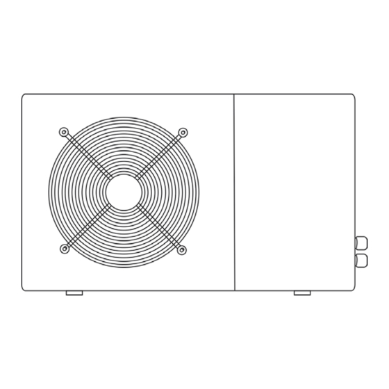
Hydro-Pro  5 User And Service Manual

Hydro-Pro 5 User And Service Manual

Swimming pool heat pump
Hide thumbs Also See for Hydro-Pro 5:

Advertisement

Swimming Pool Heat Pump
User and Service manual
English
French
Dutch
German
Russian
Polish

Advertisement

Table of Contents
loading
Need help?

Need help?

Do you have a question about the Hydro-Pro 5 and is the answer not in the manual?

Questions and answers

Summary of Contents for Hydro-Pro Hydro-Pro 5

  • Page 1 Swimming Pool Heat Pump User and Service manual English French Dutch German Russian Polish ● ● ● ● ●...
  • Page 2 INDEX FOR DIFFERENT LANGUAGES English manual………………………………..…………1~27 Manuel français………………………………..………..….28~54 Nederlandse handleiding……………………………..……55~81 Bedienungsanleitung Deutsch…………………………...82~108 инструкцию на русском………………......109~135 Polskiej firmy……………………....………..136~162...
  • Page 3 10. Maintenance 11. Warranty and returns Thank you for using HYDRO-PRO swimming pool heat pump for your pool heating, it will heat your pool water and keep the constant temperature when the air ambient temperature is at -5 to 43℃...
  • Page 4: Specifications

    1. Specifications 1.1 Technical data Hydro-Pro heat pumps Unit Hydro‐Pro  Model  5  7  10  13  18  22  22T  26T  Part number    7008324  7008317  7008318 7008319  7008320  7008321  7008322 7008323 Heating capacity    kW  5  7  10  13  18  22  22  26  A27/W27 ...
  • Page 5 2. Dimension Models 7&10 1000 1000 Unit : mm Model Hydro Pro 22, 22T, 26T - 3 -...
  • Page 6: Installation And Connection

    3. Installation and connection 3.1 Notes The factory supplies only the heat pump. All other components, including a bypass if necessary, must be provided by the user or the installer. Attention: Please observe the following rules when installing the heat pump: 1.
  • Page 7: Distance From Your Swimming Pool

    3.3 Distance from your swimming pool The heat pump is normally installed within a perimeter area extending 7.5 m from the swimming pool. The greater the distance from the pool, the greater the heat loss in the pipes. As the pipes are mostly underground, the heat loss is low for distances up to 30 m (15 m from and to the pump;...
  • Page 8: Typical Arrangement

    3.5 Typical arrangement Note: This arrangement is only an illustrative example. 3.6 Adjusting the bypass Use the following procedure to adjust the bypass: • fully open all three valves • slowly close valve 1 until the water pressure is increased by To pool From pool approximately 100 to 200 g...
  • Page 9: Electrical Connection

    3.7 Electrical connection Note: Although the heat pump is electrically isolated from the rest of the swimming pool system, this only prevents the flow of electrical current to or from the water in the pool. Earthing is still required for protection against short-circuits inside the unit. Always provide a good earth connection.
  • Page 10: Initial Operation

    3.8 Initial operation Note: In order to heat the water in the pool (or hot tub), the filter pump must be running to cause the water to circulate through the heat pump. The heat pump will not start up if the water is not circulating.
  • Page 11: Accessories List

    4. Accessories 4.1 Accessories list Anti-vibration base, 4 pcs Draining jet, 2 pcs Waterproof box, 1 pc 10M Signal wire, 1 pc Water connection assembly, 2 sets 4.2 Accessories Installation Anti-vibration bases 1. Take out 4 Anti-vibration bases 2. Put them one by one on the bottom of machine like the picture.
  • Page 12 Water Inlet & outlet junction 1. Use the pipe tape to connect the water Inlet & outlet junction onto the heat pump 2. Install the two joints like the picture shows 3. Screw them onto the water Inlet & outlet junction 10M Signal wiring 1.
  • Page 13: Electrical Wiring

    Water pump wiring 1. Connect the water pump wire through the white hole marked 2. Fix the other side on joints inside the electric box. 5. Electrical Wiring 5.1 SWIMMING POOL HEAT PUMP WIRING DIADRA Hydro Pro 5/7/10 - 11 -...
  • Page 14 5.2 SWIMMING POOL HEAT PUMP WIRING DIADRA Hydro Pro 13 - 12 -...
  • Page 15 5.3 SWIMMING POOL HEAT PUMP WIRING DIADRA Hydro Pro 18/22 - 13 -...
  • Page 16 5.4 SWIMMING POOL HEAT PUMP WIRING DIADRA Hydro Pro 22T/26T NOTE: (1)Above electrical wiring diagram only for your reference, please subject machine posted the wiring diagram. (2)The swimming pool heat pump must be connected ground wire well, although the unit heat exchanger is electrically isolated from the rest of the unit .Grounding the unit is still required to protect you against short circuits inside the unit .Bonding is also required.
  • Page 17: Display Controller Operation

    5.5 Installation of the display deportee Photo (1) Photo (2) Photo (3) - Disassembling of and degrafage control board of the connector (photo1) - Installation of the provided cable (photo 2) - To pass the cable by the press pack (photo 3) and to connect the sons directly 6.
  • Page 18: Water Temperature Setting

    Press until “heat” or “Cool” light is on. 6.4 Setting the real time On standby or running mode, long press for 10 seconds, then press to adjust hour/minute. Then press the again to store the new data. When setting the time, cannot work.
  • Page 19: Running Data Setting

    Note : If the water filtration system is stop before the heat pump, the unit will shut down (security condition) and the code EE3 or ON advertise on the controller. It is important to program the heat pump link the time program of the water filtration system. For restart the heat pump, turn off and turn on the electrical power supply to restart the unit.
  • Page 20: How To Know The Current Status

    Please kindly noted: A) Press “MODE” to choose mode (Mode only be changed for “1” or “2” setting of parameter 6) B) Mode can be changed while running C) Auxiliary electrical heating is not applicable to these modes. 7.3 How to know the current status - 18 -...
  • Page 21 - 19 -...
  • Page 22 Parameter Meaning Range Default Remarks To set the entering water temp. 8-35℃ 28℃ Adjustable under cooling mode To set the entering water temp. Adjustable 15-40℃ 28℃ under heating mode Entry into defrosting time period 30-90MIN 40MIN Adjustable Terms of Entry defrosting function -30℃to0℃...
  • Page 23: Troubleshooting

    8. Troubleshooting 8.1 Error code display on LED wire controller Malfunction Error code Reason Solution Inlet water temperature The sensor in open or short Check or change the sensor sensor failure circuit Outlet water temperature The sensor in open or short Check or change the sensor sensor failure circuit...
  • Page 24 8.2 Other Malfunctions and Solutions (No display on LED wire controller) Malfunctions Observing Reasons Solution LED wire controller Check cable and circuit No power supply no display. breaker if it is connected LED wire controller. Heat pump under standby Startup heat pump to run. displays the actual time.
  • Page 25: Exploded Diagram And Maintenance

    9. Exploded Diagram and Maintenance 9. 1 Exploded Diagram Model 5 kw - 23 -...
  • Page 26: Maintenance

    Part Name ERP code Part Name ERP code Front grill Pipes temperature sensor collet 111900004 1110040024 Front panel Pipes temperature sensor 111900004 Fan blade 113600017 Back grill 1110080042 Fan motor 11140053 Ambient temperature sensor 112200141 Fan motor bracket 1110130030 Ambient temperature sensor clip 113715001 maintain board 1110210031...
  • Page 27: Warranty And Returns

    11. Warranty and returns 11.1 Warranty LIMITED WARRANTY Thank you for purchasing a heat pump from us. This warranty covers manufacturing and material defects in all components for a period of two years after the date of purchase. This warranty is limited to the original purchaser in the retail sector. It is not transferable, and it is not applicable to products that have been removed from their original installation location.
  • Page 28: Rma Request Form

    11.2 RMA request form Company: Date: Street address: City/town: Postal Country: code: Contact: Phone: E-mail: Fax: Contact: Date: Reserved for internal use RMA no.: Assigned by: Date: Reason for return: Copy of customer invoice included? RMA request accompanied by other documents? Description of the documents: Model no.: Invoice no.:...
  • Page 29 All products received by us that lack labels or that have incorrect, incomplete or unreadable labels will be refused, with return shipping costs to be borne by you. All packages delivered to us with clearly visible damage will be refused immediately. Before returning products, please check that the products you intend to return to us are the same as the products for which an RMA number was issued.

Table of Contents

Save PDF