Sign In
Upload
Download
Table of Contents
Contents
Add to my manuals
Delete from my manuals
Share
URL of this page:
HTML Link:
Bookmark this page
Add
Manual will be automatically added to "My Manuals"
Print this page
×
Bookmark added
×
Added to my manuals
Manuals
Brands
Hydro-Pro Manuals
Heat Pump
7024525
Installation instructions manual
Hydro-Pro 7024525 Installation Instructions Manual
Swimming pool heat pump unit
Hide thumbs
1
Table Of Contents
2
3
4
5
6
7
8
9
10
11
12
13
14
15
16
17
18
19
20
21
22
23
24
25
26
27
28
29
30
31
32
33
34
35
36
37
38
39
40
41
page
of
41
Go
/
41
Contents
Table of Contents
Troubleshooting
Bookmarks
Table of Contents
Table of Contents
1 Preface
2 Specifications
Performance Data of Swimming Pool Heat Pump Unit
Dimensions for Swimming Pool Heat Pump Unit
3 Installation and Connection
Installation Illustration
Swimming Pool Heat Pumps Location
How Close to Your Pool
Swimming Pool Heat Pumps Plumbing
Swimming Pool Heat Pumps Electrical Wiring
Initial Startup of the Unit
4 Use and Operation Instruction of Wire Controller
Function of Controller
The Controller Usage
Parameter Table
Trouble Shooting Guide
Connection of PCB Illustration
5 Maintenance and Inspectio
6 Appendix
Circuit Diagram
Cable Specification
Comparison Table of Refrigerant Saturation Temperature
Advertisement
Quick Links
1
Performance Data of Swimming Pool Heat Pump Unit
2
Installation Illustration
3
Installation and Connection
4
Swimming Pool Heat Pumps Electrical Wiring
5
Function of Controller
6
Use and Operation Instruction of Wire Controller
7
The Controller Usage
8
Trouble Shooting Guide
Download this manual
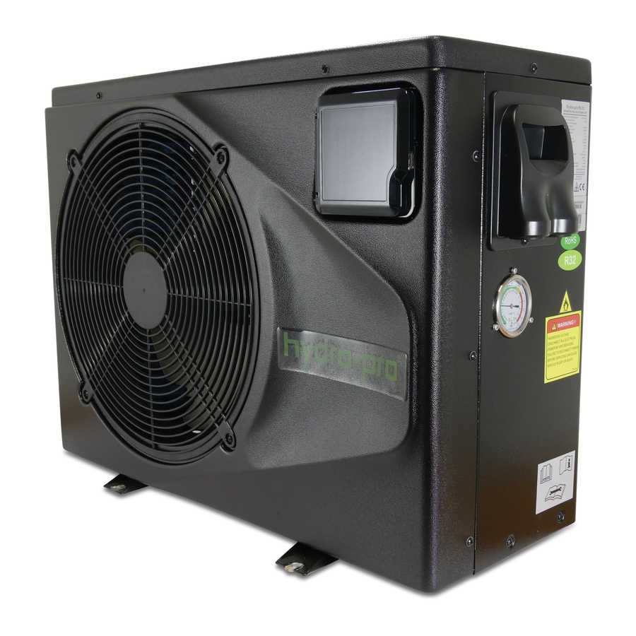
SWIMMING POOL HEAT PUMP UNIT
Installation & Instruction Manual
Part no.
7024524
7024525
7024526
7024527
7024528
7024529
7024530
7024531
EN
Type
P6/32
P8/32
P12/32
P14/32
P20/32
P23/32
P23T/32
P26T/32
Table of
Contents
Previous
Page
Next
Page
1
2
3
4
5
Advertisement
Table of Contents
Need help?
Do you have a question about the 7024525 and is the answer not in the manual?
Ask a question
Questions and answers
Related Manuals for Hydro-Pro 7024525
Heat Pump Hydro-Pro Hydro-Pro 5 User And Service Manual
Swimming pool heat pump (30 pages)
Heat Pump Hydro-Pro Hydro-Pro+Premium 7 Installation Instructions Manual
Swimming pool heat pump unit (202 pages)
Heat Pump Hydro-Pro 5 User And Service Manual
(196 pages)
Heat Pump Hydro-Pro 7018522 User And Service Manual
Swimming pool heat pump (193 pages)
Heat Pump Hydro-Pro INVERBOOST+ Tech Series Service Manual
Swimming pool heat pump (186 pages)
Heat Pump Hydro-Pro Inverter 5 User And Service Manual
Swimming pool heat pump (119 pages)
Heat Pump Hydro-Pro Inverter 14 User And Service Manual
Swimming pool heat pump (176 pages)
Heat Pump Hydro-Pro Hydro-Pro+ Premium 22M Installation Instructions Manual
Swimming pool heat pump unit (145 pages)
Heat Pump Hydro-Pro PV 13 Installation Instructions Manual
Swimming pool heat pump unit (32 pages)
This manual is also suitable for:
7024524
7024528
7024529
7024530
7024531
P6/32
...
Show all
P8/32
P12/32
7024526
7024527
P14/32
P20/32
P23/32
P23t/32
P26t/32
Table of Contents
Print
Rename the bookmark
Delete bookmark?
Delete from my manuals?
Login
Sign In
OR
Sign in with Facebook
Sign in with Google
Upload manual
Upload from disk
Upload from URL


Need help?
Do you have a question about the 7024525 and is the answer not in the manual?
Questions and answers