Escea DX-Series Installation & Service Manual
Gas fireplace
Hide thumbs
Also See for DX-Series:
- User manual (12 pages) ,
- User manual (16 pages) ,
- User instructions (14 pages)
Table of Contents
Advertisement
Quick Links
See also:
User Manual
Advertisement
Table of Contents

Related Manuals for Escea DX-Series


Summary of Contents for Escea DX-Series
- Page 1 Installation / Service Guide DX-Series Gas Fireplace GB / IE EDITION For the latest documentation, visit www.escea.com 630247_8...
- Page 3 Installation must be carried out by a registered installer who, on completion of the installation, must issue a certificate of compliance, in accordance with national and/or local codes. If a certificate of compliance is not issued then the Escea warranty may be void.
-
Page 4: Table Of Contents
Installation Process and Product Description Recommended Installation Process: Product Description Product Dimensions Creating the Cavity Cavity Shape Designing the Cavity Flue Configuration Recommended Framing Dimensions Cavity Base Hearth Wall Linings Fascia Mantle Clearance Television Clearances Ducting Duct Fan mounting Installing the Electricity and Gas to the Appliance Power Supply Network Cable Gas Pipe Sizing... - Page 5 Cleaning the Fuel bed and Glass Checking Operating Pressure Replacing a Remote Control Replacing the burners Accessing the control tray Removing the Circuit Board Servicing the Horizontal / Vertical Powerflue Wiring Diagram Escea product warranty Access to Fans - Installer to fill in...
-
Page 6: Installation Process And Product Description
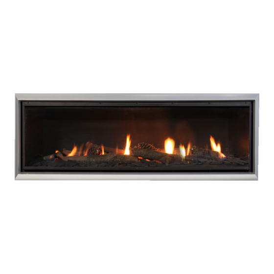
Section F Product Description The Escea DX1000 / DX1500 gas fire is a direct vent (fan draught balanced flue), room sealed gas appliance designed to be built into a cavity. This appliance is flued using a co- linear rigid polypropylene flue connected to a powerflue terminal. -
Page 7: A3 Product Dimensions
Product Dimensions NOT TO BE MISTAKEN FOR CAVITY DIMENSIONS All dimensions are in mm DX1000 DX1500 664mm 914mm 1328mm 1828mm... -
Page 8: Creating The Cavity
Flue Configuration ONLY USE ESCEA APPROVED FLUE COMPONENTS The entire flue system must be constructed from M+G (Duravent) PolyPro. There are two basic types of flue configuration, using a vertical powerflue cowl, or a horizontal powerflue cowl. - Page 9 ROOF TERMINAL ROOF TERMINAL 100/150 COAXLINE 100/150 COAXLINE CONDENSATE TRAP CONDENSATE TRAP ESCEAV-BOX ESCEA V-BOX 100/150 COAXLINE MUGRO WALL TERMINAL ESCEA WALL TERMINAL ESCEAV-BOX UPTO 12mMAX UPTO 12mMAX 100/150 PP 80+100 PP 80+100 TWINLINE TWINLINE 100 CONDENSATE TRAP 100 CONDENSATE TRAP...
-
Page 10: B4 Recommended Framing Dimensions
The flue must be securely fixed and adequately supported by brackets fastened to the building structure at suitable points to ensure the stability of the flue system. Any joints within the flue system must be supported with the correct brackets to prevent the flue system from coming apart. -
Page 11: B6 Hearth
WALL OPENING (WITH FASCIA) FASCIA Note that 10mm (or less) wall lining must be used when installing a DX-series fireplace with a fascia, as this is the distance the fascia sits off the front face of the fire as shown. -
Page 12: B9 Mantle Clearance
Escea in no way guarantees or takes responsibility that the above installation suggestion will be suitable for all electrical or home entertainment appliances. -
Page 13: B12 Duct Fan Mounting
Ductwork must not be crushed or exposed to excessive heat sources. Note: If duct backpressure is too great, the appliance can shut down due to overheating. This ducting fan will generate mechanical noise. Ideally it must be installed in a position where noise will not interfere with daily activities. -
Page 14: Installing The Electricity And Gas To The Appliance
Installing the Electricity and Gas to the Appliance Power Supply While the cavity is being created consideration should be given to appropriate location of a standard 3 pin, EARTHED 230/240V power outlet. This must be within 1.0m of the bottom right of the appliance. - Page 15 If you do not wish to connect the fireplace to the modem, the Network / Ethernet cable should be run to somewhere accessible by a service technician, such as a cupboard.
-
Page 16: C3 Gas Pipe Sizing
Gas Pipe Sizing Gas pipe should be sized appropriately. The pipe sizing must be sufficient to deliver the following volume of gas to the heater with all other gas appliances in the home running at the same time: DX1500 Gas Consumption = 12.0kW DX1000 Gas Consumption = 9.9kW Gas Pipe Position The gas connection is inside the appliance and is ½”... -
Page 17: Installing The Flue
Installing the Flue D1 Flue Type Overview Note: The appliance is designed to operate using the approved flue supplied by Escea. Using other brands of flue may affect the appliance warranty. There are 3 types of flue terminals, and these vary depending on your countries climate. - Page 18 (Supported) Kit: 926601 EU Cold Climate Horizontal Flue Kit Contains: 1x 100/150 Coaxline Murgo Wall Terminal 1x Escea ‘V’ Box 4x 1m x 100mm PolyPro Flue 4x 1m x 80mm PolyPro Flue 6x 100mm Brackets 6x 80mm Brackets 1x 100mm PolyPro Condensate trap 1x 90º...
-
Page 19: D2 Installing The Wall Terminal For Temperate Climates Only
D2 Installing the Wall Terminal for Temperate Climates only If you are located in a temperate climate, as specified at the start of section D, this flue type should be used. The Horizontal Powerflue Wall Terminal must be installed in the correct orientation. - Page 20 Horizontal Powerflue Wall Terminal to these, from the front: How to flash the Horizontal Powerflue The following diagrams are excerpts from the escea architect drawings, and are available in full on our website. These diagrams are recommendations only, and your installation must comply with any local or national building codes, therefore these recommendations may need to be modified to suit.
-
Page 21: D3 Installing The Wall Terminal For Cold Or Temperate Climates
Mugro Wall Terminal 100/150 Escea V-Box Co-Axial (Supported) The Escea V-Box should then be installed directly off the terminal as shown above, and fixed in place to building framing or other suitable fixtures. Continue to section D5... -
Page 22: D4 Installing The Vertical V-Box Roof Terminal Option
Note the length of flue up to the Escea V-box Mugro Roof must be no more than 12m. -
Page 23: D5 Locating The Terminal
D5 Locating the Terminal The flue terminal must be located using the information given in the following excerpts from BS 5440-1. - Page 24 If using a horizontal flue terminal, a guard must be fitted to the terminal where it is located less than 2m above the ground, above a balcony or flat roof to which people have access. This guard is available from your nearest escea retailer.
-
Page 25: D6 Running The Flue
D6 Running the Flue Run the Ø100mm and Ø75mm PP flue from the cavity to the V-box or Horizontal Power- flue using no more than 4x 90º bends. The flue system for the DX1000 / DX1500 is zero rated, so no spaces are required between the flue and any timber framing. NOTE: Any horizontal flue runs should slope upwards towards the fan unit at a rate of 20mm per 1000mm, and 3º... - Page 26 Wall Bracket Fixing (Brick / Concrete) The wall bracket has a shaft that should be fixed securely before offering up the flue sec- tion for assembly. The wall bracket shaft should be fixed into brick or concrete by : Mark out the run of the flue including the 3° fall back to the condensate trap. Fix a suitably sized plastic wall plug into the brick or concrete in the required position (noting the length of the wall bracket shaft).
-
Page 27: D7 Condensate Control
D7 Condensate Control On long flue lengths (over 4 metres) the D Series fires may generate condensate continu- ously at a rate of up to 0.5 litres per hour. The control of this condensate is important to both the function of the appliance and the integrity of the building therefore the conden- sate must be drained to a suitable discharge point. - Page 28 Internal Condensate disposal. Wherever possible, the condensate drainage pipe should be terminated at a suitable internal foul water discharge point such as an internal soil and vent stack or an internal kitchen or bathroom waste pipe, washing machine waste pipe, etc. A suitable permanent connection to the foul waste pipe should be used.
- Page 29 Internal Condensate disposal Option 2...
- Page 30 External Condensate Disposal The use of an externally-run condensate drainage pipe, terminating at a suitable foul water discharge point or purpose-designed soak-away is acceptable, however if this termination method is chosen then the following measures should be adopted The pipe should be run internally as far as possible before going externally and the pipe diameter should be increased to a minimum of 32mm outside diameter before it passes through the wall (this is to reduce the possibility of freezing in extended periods of cold weather).
-
Page 31: D8 Running The Powerflue Electrical Cable
A weather-tight Wall or Roof Terminal installation with clearance as specified BS 5440-1 Reasonable access to the Horizontal Powerflue or Escea V-box for maintenance Flue attached to the Powerflue or V-box and fireplace The electrical cable from the Powerflue or V-box attached to the rear of the... -
Page 32: Installing The Appliance
Installing the Appliance Double Sided conversion If the appliance is to be double sided, you will have been supplied with an extra glass panel and steel support frame and wall lining trim brackets. 1. On the rear of the appliance, unscrew the outer shell cover and remove it as shown 2. -
Page 33: E2 Installing The Appliance
Installing the Appliance Insert the gas fire into the cavity and bolt down in correct posi- tion using the brackets on each end of the appliance. It is a requirement that this appliance be securely fastened at the base. On the right hand side of the appliance: Connect the powerflue electrical cable. -
Page 34: E4 Connecting The Air Ducting
Drill and Step 6: Locate the Ø80mm x 115 long rivet 2x powerflue adaptor and apply a Ø5mm bead of silicone all around the inside circumference of 80Ø the adaptor at the smaller diameter end. Add RTV Silicone 100Ø 100Ø Step 7: Push the adaptor (silicone bead end) over the inlet spiggot of the powerflue box until... -
Page 35: E7 Remove The Fuelbed Tray & Burners
WARNING: The regulator that is supplied with the fire MUST NOT BE REMOVED. Removal of the regulator, or replacing it with one not intended for use with this Escea fire, will void the limited appliance warranty. Turn off power and gas first. - Page 36 Remove ‘engine’ by lifting up and to the left. This is still connected internally to the gas hose and power cables. Place engine just to the left within firebox as shown. Step 4: Change the two main burner jets with the jets supplied in kitset. DX1500 DX1000 Natural Gas (G20) (Both jets)
- Page 37 Step 7: Cover the existing Dataplate label with the new gas conversion label supplied in kitset. Ensure serial number and date of manufacture are still visible. Write your name, company (if appropriate) and date of conversion on new label with permanent marker. Adhere the supplied Gas Type Label to the outside of the product, covering the existing gas type label.
-
Page 38: E9 Checking The Gas Operating Pressure
MUST NOT BE REMOVED. Removal of the regulator, or replacing it with one not intended for use with an Escea fire, will void the limited appliance war- ranty and may be dangerous. The gas valve is shown right with Manometer test points at A and C, and an adjustment point at B. - Page 39 Specification Table - DX1500 Gas Category: II 2H3P Gas Type Natural Gas (G20) Propane (G31) Gas Group Supply Pressure 20 ± 1.5 mbar 37 mbar Regulator Outlet Pressure (C) 10 mbar 23 mbar Burner Pressure on High (A) 7.7 mbar 19.6 mbar Burner Pressure on Low (A) 3.8 mbar...
-
Page 40: E10 Operating The Appliance
If unable to acheive pressures from table in E9: Adjust point B (shown in previous section) with a 3mm allen key to adjust the LOW setting, and a 2mm allen key to adjust the HIGH setting. NOTE: Do not use a ball-end allen key. Use only square- end allen keys for adjusting this point. -
Page 41: E11 Auxillary On/Off Button
E12 Home Automation Setup Escea D-Series fireplaces have a simple interface for connection to a home automation system. Simply put this allows the fireplace to be woken up and started and then shut down. The “Close to wake” connection shown is essentially taking one of the 3.3 volt DC pins on the fireplace micro controller and pulling it down to ground. - Page 42 Home Automation Operation: Relay closed The fireplace will start in a medium setting until it receives a signal from the remote con- trol unit (up to 4 minutes). Once the remote has communicated with the fireplace it will turn on and begin operating the fireplace thermostatically. The remote will use whatever temperature the user has previously set and cannot be altered by the home automation system.
-
Page 43: Finishing The Installation
Finishing the Installation Crystalite or Coal Fuel Bed Installation If using the Crystalight or Coal fuel beds, first place all the media pieces in a single layer atop the Burners and Fuelbed Tray. Cover the entire area except for the pilot shield, ensur- ing coverage right up to both glass windows and rear of firebox for single sided. -
Page 44: F2 Wall Lining
Note: If the glass gasket requires a replacement, call your nearest Escea agent who will ensure the part is replaced with the correct type. In the event that the glass is broken by impact, purchase the replacement from an authorised Escea agent only. -
Page 45: F3 Fitting The Fascia Panels
Fitting the Fascia Panels To avoid scratches or knocks to the fascia panels of this heater they must be fitted at the complete conclusion of the installation process, after wall linings are in place. Note: Never ever rub the fascia. Step 1: Ensure the plastic spacer is placed on the thread of the studs. -
Page 46: F4 Locating Wall Mount Cradle For Wireless Control
A suitable distance away from the heater Ideally 1.2m to 1.5m from the floor The radio frequency signal will go through some walls but for best results Escea suggest that the cradle position is less than 10 metres away from the heater and in the same room. -
Page 47: F6 Final Checklist
Run the appliance again and check the operation of the thermostat by increasing and re- ducing the set temperature. Check the Flame Effect function and the Fan Boost functions work correctly. For further operation instructions please refer to the User Guide. Final checklist Run the appliance on full for an hour with the doors &... -
Page 48: F7 Normal Operating Sounds And Smells
Fan: Escea gas appliances use electric fans to push heated air into the room. It is not unusual for the fan to make a “whirring” sound when ON. This sound will increase or decrease in volume depending on the speed setting of your fan. -
Page 49: Installation Checklist
Installation Checklist Go through the following checklist to ensure you have installed the appliance correctly Correctly sized cavity to suit your fascia and flue configuration Correct clearances to combustibles and mantles around the fascia An electrical isolating switch to the appliance, accessible after finished installation Correctly sized gas supply with a pressure test point, ensuring adequate supply with all other gas appliances in the dwelling running A weather-tight installed Horizontal or Vertical Terminal with clearance as specified by... -
Page 50: Service Manual
Service Manual IMPORTANT: • This appliance must be serviced every 12 months. • Any service operation should be carried out only by a suitably qualified and trained person. • Gas and electricity supply MUST be isolated before any service operation is carried out on this appliance. -
Page 51: S2 Error Codes
Error Codes This gas fire has been designed to show error codes to help explain and identify any fault situation that occurs. These codes will appear on the wireless remote control in the form of a large letter “E” with a number beside it. Codes can normally be reset by turning the heater off then on again at the wall. - Page 52 The bimetallic snap disk mounted on the exhaust collector box has tripped. The possible causes for this could include: • Possibly fascia panels installed incorrectly resulting in restricted air flow. Appliance Over • Room air fans may be slowed or stalled. Check that fans are plugged Temperature in, cleaned, and free turning Sensor Trip...
-
Page 53: S3 Cleaning The Fuel Bed And Glass
The outside of the fascias must only be cleaned with a clean damp cloth, dry off after cleaning. The high temp silver powder coating that is used on Escea fascia parts contains certain amounts of aluminium that when rubbed too hard will oxidise leaving a black smudge that cannot be removed. - Page 54 Step 5: Reinstate fuel media and glass and test run heater. NOTE WHEN REPLACING THE GLASS: When replacing the glass, note that the metal flange shown to the right must be on top (not the bottom), or the glass will not fit correctly to the fireplace.
-
Page 55: S4 Checking Operating Pressure
Checking Operating Pressure WARNING: The regulator that is supplied with the fire MUST NOT BE REMOVED. Removal of the regulator, or replacing it with one not intended for use with an Escea fire, will void the limited appliance warranty. Note: Access to the valve and control system can be through either of the 2 hatch panels shown shaded black in the diagram to the right. -
Page 56: S5 Replacing A Remote Control
Replacing a Remote Control If the wireless control becomes lost or damaged, a new one can be ordered from any Escea retail agent. When you have the new remote, the following procedure needs to be followed to “teach” the remote to only communicate with that fire. -
Page 57: S6 Replacing The Burners
Replacing the burners If a fascia is fitted, remove this first. Using the supplied 3mm Allen Key (hex drive) remove the bolts around the glass retainer ensuring that the glass does not fall forward. Pull the top of the frame toward you slightly and lift the glass and frame out and away from the fire. -
Page 58: S7 Accessing The Control Tray
Accessing the control tray Remove the screws in the bottom and the inner side of the firebox as per shown. Remove the ‘engine’ by lifting up and to the left. This is still connected internally to the gas hose and power cables. Place engine just to the left within firebox as shown. Removing the Circuit Board Step 1: Remove the Pilot cover and 2 jets circled to the... - Page 59 Step 3: Remove the clear plastic insulation cover from ontop of the circuit board by removing the screws circled below. Step 4: Remove all 5 connections to the circuit board as highlighted below. Step 5: Remove any screws securing the circuit board to the base and remove the circuit board.
-
Page 60: S9 Servicing The Horizontal / Vertical Powerflue
Servicing the Horizontal / Vertical Powerflue Ensure the power to the Powerflue is off by disconnecting the power to the appliance inside. If the appliance has been running, allow the Powerflue to cool before attempting to service it. Servicing a horizontal Powerflue: If the Powerflue needs servicing, the fan can be accessed from the outside of the instal- lation for Horizontal termination, and accessed from within the roof space for Vertical termination. -
Page 61: S10 Wiring Diagram
S10 Wiring Diagram... -
Page 63: S11 Escea Product Warranty
Warranty period without the prior written consent of ESCEA then the Limited Warranty shall be void. ESCEA may, at its sole discretion, decide that the Limited Warranty is void in relation to any part of the product, which has been modified. -
Page 64: S12 Access To Fans - Installer To Fill In
ESCEA reserves the right to discontinue products or make substitutions, in such event, the buyer may receive a substitute product or a cash refund at ESCEA’S sole discretion, if a replacement for the product covered by this Limited Warranty is no longer available.
Need help?
Do you have a question about the DX-Series and is the answer not in the manual?
Questions and answers