LevelOne FSW-1609TFX User Manual
16/24 port 10/100mbps fast ethernet switch
Hide thumbs
Also See for FSW-1609TFX:
- Specifications (2 pages) ,
- Brochure (86 pages) ,
- User manual (27 pages)
Table of Contents
Advertisement
Quick Links
Download this manual
See also:
User Manual
Advertisement
Table of Contents

Related Manuals for LevelOne FSW-1609TFX


Summary of Contents for LevelOne FSW-1609TFX
- Page 1 LevelOne FSW-1609TFX FSW-2409TFX 16/24 Port 10/100Mbps Fast Ethernet Switch User’s Guide...
-
Page 2: Fcc Warning
FCC Warning This equipment has been tested and found to comply with the regulations for a Class B digital device, pursuant to Part 15 of the FCC Rules. These limits are designed to provide reasonable protection against harmful interference when the equipment is operated in a commercial environment. -
Page 3: Table Of Contents
ABLE OF ONTENTS ABOUT THIS GUIDE................III URPOSE ....................ERMS SAGE ..................’ VERVIEW OF THIS UIDE..........INTRODUCTION ..................11 THERNET ECHNOLOGY ............11 WITCHING ECHNOLOGY ..............12 EATURES ....................13 UNPACKING AND INSTALLATION..........15 NPACKING....................16 NSTALLATION ..................16 100B -FX M ODULE NSTALLATION........17 OUNTING................18 RONT ANEL..................20 ANEL..................21... - Page 4 A. Using straight cable ..............25 B. Using crossover cable ..............25 & D PEED UPLEX ODE.............25 TECHNICAL SPECIFICATIONS ............19 RJ-45 PIN SPECIFICATION ............... 21...
-
Page 5: About This Guide
This device integrates 100Mbps Fast Ethernet and 10Mbps Ethernet network capabilities in a highly flexible package. Purpose This guide discusses how to install your LevelOne 16/24Port 10/100Mbps Fast Ethernet Switch. Terms/Usage In this guide, the term “ Switch” (first letter upper case) -
Page 6: Overview Of This User's Guide
Overview of this User’s Guide Chapter 1, Introduction. Describes the Switch and its features. Chapter 2, Unpacking and Installation. Helps you get started with the basic installation of the Switch. Chapter 3, Identifying External Components. Describes the front panel, rear panel and LED indicators of the Switch. -
Page 7: Introduction
NTRODUCTION This chapter describes the features of the Switch and some background information about Ethernet/Fast Ethernet switching technology. Fast Ethernet Technology The growing importance of LANs and the increasing complexity of desktop computing applications are fueling the need for high performance networks. A number of high-speed LAN technologies have been proposed to provide greater bandwidth and improve client/server response times. -
Page 8: Switching Technology
Switching Technology Another approach to pushing beyond the limits of Ethernet technology is the development of switching technology. A switch bridge Ethernet packets at the MAC address level of Ethernet protocol transmitting among connected Ethernet or Fast Ethernet LAN segments. Switching is a cost-effective way of increasing the total network capacity available to users on a local area network. -
Page 9: Features
Switching LAN technology is a marked improvement over the previous generation of network bridges, which were characterized by higher latencies. Routers have also been used to segment local area networks, but the cost of a router, the setup and maintenance required make routers relatively impractical. - Page 10 upgrade to Fast Ethernet in the future. Ethernet workgroups can connect to the Switches now, and change adapters and hubs anytime later without needing to change the Switches or reconfigure the network. The Switches combine dynamic memory allocation with store-and-forward switching to ensure that the buffer is effectively allocated for each port, while controlling the data flow between the transmit and receive nodes to guarantee against all possible packet loss.
-
Page 11: Unpacking And Installation
is only available in half duplex mode. Data forwarding rate per port is at wire-speed for 100Mbps speed. Data forwarding rate per port is at wire-speed for 10Mbps speed. Data filtering rate eliminates all error packets, runts, etc., per port at wire-speed for 100Mbps speed. Data filtering rate eliminates all error packets, runts, etc., per port at wire-speed for 10Mbps speed. -
Page 12: Unpacking
Unpacking Open the shipping cartons of the Switch and carefully unpacks its contents. The carton should contain the following items: One the LevelOne FSW-1609/2409TFX 16/24Port 10/100Mbps Fast Ethernet Switch One AC power cord, suitable for your area’s electrical power connections... -
Page 13: 100Base-Fx Module Installation
Leave at least 10cm of space at the front and rear of the hub for ventilation. Install the Switch on a sturdy, level surface that can support its weight, or in an EIA standard-size equipment rack. For information on rack installation, see the next section, Rack Mounting. -
Page 14: Rack Mounting
We recommend that you retain the dust cover in case you need to remove the module for an extended period sometime in the future. In 16/24 Port model, port 16 and the 100BASE-FX port is really the same port. Do not use both Port 16 and the 100BASE-FX port as the same time. - Page 15 Then, use screws provided with the equipment rack to mount each switch in the rack. Identifying External Components This section identifies all the major external components of...
-
Page 16: Front Panel
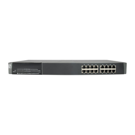
the switch. Both the front and rear panels are shown, followed by a description of each panel feature. The indicator panel is described in detail in the next chapter. Front Panel The figure below shows the front panels of the switches. 16-port 10/100M Fast Ethernet Switch 24-port 10/100M Fast Ethernet Switch LED Indicator Panel... -
Page 17: Rear Panel
Card) or switches and hubs. Rear Panel LevelOne 16/24 Port 10/100Mbps Fast Ethernet Switch Module Slots: Used to install module options for 100BASE-FX connection. AC Power Connector: For the power cord. -
Page 18: Led Indicators
LED Indicators Power Indicator (PWR) This LED lights green when the switch is receiving current; if not, power is off. 100M Link/Activity, 10M Link/Activity (100M LINK/ACT , 10LINK/ACT (green) (yellow) This indicator light green when the port is connected to a 100Mbps Fast Ethernet station, if the indicator blinking green will be transmitting or received data on the 100Mbps network. -
Page 19: Connecting The Switch
ONNECTING WITCH This chapter describes how to connect the Switch to your Fast Ethernet network. PC to Switch A PC can be connected to the Switch via a two-pair Category 3, 4, 5 UTP/STP straight cable. The PC (equipped with a RJ- 45 10/100Mbps phone jack) should be connected to any of the 16 ports (1x - 16x) for the 16Port model, 24 ports (1x - 24x) for the 24Port model... -
Page 20: 10Base-T Hub
via a two-pair Category 3, 4, 5 UTP/STP cable. connection is accomplished from the hub uplink (MDI-II) port to any port of the Switch (MDI-X) ports. A. 10BASE-T Hub For a 10BASE-T hub, the Switch LED indicators should light up as the following: “10/100M FDX, 10/100M COL”... -
Page 21: Switch To Switch (Other Devices)
When using straight cable, this is done from the uplink (MDI-II) port of other Switch to any of the 10Mbps or 100Mbps (AUTO MDI-X) port of FSW-1609TFX/ 2409TFX. B. Using crossover cable When using crossover cable, this is done from any (MDI-X) port of the Switch (Switch A) to any of the 10Mbps, 100Mbps (AUTO MDI-X) port of FSW-1609TFX/ 2409TFX. - Page 22 attached device does support auto- negotiation or has auto-negotiation disabled, an auto- sensing process is i nitiated to select the speed and set the duplex mode to half-duplex.
-
Page 23: Technical Specifications
ECHNICAL PECIFICATIONS General Standards IEEE 802.3 10Base-T Ethernet IEEE 802.3u 100 Base-TX Fast Ethernet ANSI/IEEE 802.3 NWay auto-negotiation Protocol CSMA/CD Data Ethernet: 10Mbps (half duplex) Transfer 20Mbps (full duplex) Rate Fast Ethernet: 100Mbps (half duplex) 200Mbps (full duplex) Topology Star Network 10BASET: 2 -pair UTP Cat. -
Page 24: Physical And Environmental
Physical and Environmental AC inputs 100 to 240 VAC, 50 or 60 Hz internal universal power supply Power 10 watts. (max.) for FSW-1609TFX Consumption 20 watts. (max.) for FSW-2409TFX Temperature Operating: 0° ~ 50° C, Storage: -10° ~ 70° C... -
Page 25: Pin Specification
RJ-45 P PECIFICATION When connecting your Level One 16/24/32Port 10/100Mbps Fast Ethernet Switch to another switch, a bridge or a hub, a modified crossover cable is necessary. Please review these products for matching cable pin assignment. The following diagram and tables show the standard RJ-45 receptacle/connector and their pin assignments for the switch-to-network adapter card connection, and the straight / crossover cable for the Switch-to-switch / hub / bridge... - Page 26 The standard RJ-45 receptacle/connector The following shows straight cable and crossover cable connection: Straight cable for Switch (uplink MDI-II port) to switch/Hub or other devices connection Crossover cable for Switch (MDI-X port) to switch/hub or other network devices (MDI-X port) connection...
Need help?
Do you have a question about the FSW-1609TFX and is the answer not in the manual?
Questions and answers