
Related Manuals for LevelOne FSW-1671


Summary of Contents for LevelOne FSW-1671
- Page 1 LevelOne User Manual FSW-1671 16-Port 10/100 Rackmount Smart Switch w/8 PoE Ports Ver1.0-0905...
- Page 2 FCC Warning This Equipment has been tested and found to comply with the limits for a Class-A digital device, pursuant to Part 15 of the FCC rules. These limits are designed to provide reasonable protection against harmful interference in a residential installation.
-
Page 3: Table Of Contents
Content Introduction........................1 Features ........................ 1 Package Contents ....................2 Hardware Description ....................3 Front Panel ......................3 LED Indicators ..................... 3 Rear Panel ......................4 Desktop Installation ....................5 Rack-mounted Installation ..................5 Power On ......................5 Web-Based Management ....................6 About Web-based Management ................ - Page 4 MAC Address Binding .................32 Miscellaneous ......................34 Output queue aging ..................35 Stride VLAN ....................35 IGMP Snooping ...................35 Logout .........................36 Load default Setting –hardware based..............36 Troubleshooting ......................37 Incorrect connections ...................37 Faulty or loose cables...................37 Non-standard cables ..................37 Improper Network Topologies ..............37 Diagnosing LED Indicators ................38 Cabling ......................38 Technical Specification ....................39 Appendix ........................41...
-
Page 5: Introduction
Introduction Web Smart for Intelligent Networks FSW-1671 switch is a Web Smart Switch equipped with 16 10/100 Mbps ports with auto-MDI/MDIX crossover detection function. 8 of those ports are also built with PoE functionality, providing the ultimate choice in network flexibility. With this added PoE feature, FSW-1671 is an ideal solution for building wireless, IP surveillance, and VoIP networks. -
Page 6: Package Contents
Package Contents Unpack the package of FSW-1671 Smart Switch and verify them against the checklist below: FSW-1671 Web Smart Switch Power Cord Rack-mount brackets User Manual CD Compare the contents of FSW-1671 Web Smart Switch package with the standard checklist above. If any item is missing or damaged, please contact the local dealer for... -
Page 7: Hardware Description
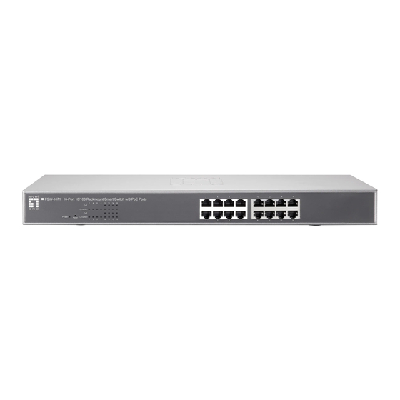
The FSW-1671 Smart Switch physical dimensions is 440mm x 220mm x 44mm (WxDxH) Front Panel The front panel of the FSW-1671 Web Smart Switch consists of 16 x 10/100Base-TX RJ-45 ports (Auto MDI/MDIX). The LED Indicators are also located on the front panel of the switch. -
Page 8: Rear Panel
No device attached Rear Panel The 3-pronged power plug is located at the rear panel of the FSW-1671 switch shown as below. The switch will work with AC in the voltage range between 90V to 260V and Frequency of 50-60Hz... -
Page 9: Desktop Installation
Rack-mounted Installation The FSW-1671 Web Smart Switch comes with a rack-mounted kit and can be mounted in an EIA standard size, 19-inch Rack. The switch can be placed in a wiring closet with other equipment. -
Page 10: Web-Based Management
Notice: FSW-1671 smart switch support browser IE 6.0 – 7.0 / Firefox 2.0-3.0 User Login Launch the Internet Explorer. - Page 11 Note: It will show error message if you key in wrong user name or password...
-
Page 12: Main Page
Main Page Administrator Administrator includes Authentication Configuration/System IP Configuration/ System Status/ Load default setting/Firmware Update/ Reboot Device Authentication configuration Change web management login user name and password for the management security issue. Username: Type in the new user name (The default value is ‘admin’). Password: Type in the new password (The default value is ‘admin’). -
Page 13: System Ip Configuration
Note: Username & Password only accept "a-z","A-Z","0-9","-","_" System IP Configuration This page shows system configuration including the current IP address and sub-net mask and Gateway. User can configure the IP settings, Subnet Mask, Gateway as below: IP address: Manually assign the IP address that the network is using. The default IP is 192.168.1.1 Subnet Mask : Assign the subnet mask to the IP address... -
Page 14: System Status
Gateway: Assign the network gateway for industrial switch. The default gateway is 192.168.1.254 If you change the IP address of this switch and then press, “update” It will show “update successfully” then press Reboot button. It will enter user log in screen automatically System status This page displays the information about the switch’s MAC address, how many ports it has, system version and kernel version. -
Page 15: Load Default Setting
Load default setting Clicking the “load” button will make the switch being set to the original configuration. Note: It exclude to change user name, password and IP configuration. If you want to restore default setting including IP and user name password , then you can press the reset button for hardware base reset. - Page 16 After pressing update button, the old web code will be erased. Then you can select the image file and press “update” button to update the firmware you need..
-
Page 17: Reboot Device
TFTP firmware update Users can get into the command prompt window to proceed. The command prompt window can be opened by entering “cmd” (without quotes) into Start-Run or through Start-All Programs-Accessories. A black and white window ( the color can be changed) containing the command prompt will open. -
Page 18: Port Management
Note: The reboot is for software base instead of hardware base. Port Management Port Management includes Port Configuration, Port Mirroring , Bandwidth Control, Broadcast Storm Control and PoE Port configuration In Port Configuration, you can set and view the operation mode for each port. Auto-Negotiation: Enable and Disable. -
Page 19: Port Mirroring
Backpressure: Flow Control for connection at speed of 10/100Mbps in Half-duplex mode. TX Capability: When the Auto-Negotiation column is set as Disable, users have to set this column as Enable or Disable. Addr. Learning: When the Auto-Negotiation column is set as Disable, users have to set this column as Enable or Disable. -
Page 20: Bandwidth Control
Monitored Pckets: Pull down the selection menu to choose what kind of packet is to be monitored. Source Port: The ports that the user wants to monitor. All monitored port traffic will select multiple source ports be copied to mirroring (destination) port. Users can by ticking the check boxes beneath the port number label to be monitored. - Page 21 selected bandwidth resolution to get the actual bandwidth. (a) Low bandwidth for TX Example 1: The TX number of the port1~4 is set to 10, 20, 30, 40 respectively, and Speed base is set to “low”. The real bandwidth comes from the formula of 32Kbps*10, 32Kbps*20 and 32Kbps*30 respectively.
- Page 22 Example 2: The TX number of the port1~4 is set to 10, 20, 30, 40 respectively, and Speed base is set to “High”. The real bandwidth comes from the formula of 512Kbps*10, 512Kbps*20 and 512Kbps*30 respectively. After the “update” button is executed, the real bandwidth will show up in TX fields.
- Page 23 Example 3: The RX bandwidth number of the port 5~ port 8 is set to 50, 60, 70, 80 respectively, and Speed base is set to “low”. The real bandwidth comes from the formula of 32Kbps*50, 32Kbps*60, 32Kbps*70 and 32Kbps*80 respectively After the “update”...
-
Page 24: Broadcast Storm Control
Broadcast Storm Control The switch implements a broadcast storm control mechanism. Tick the check boxes to have them beginning to drop incoming broadcast packets if the received broadcast packet counts reach the threshold defined. Each port’s broadcast storm protection function can be enabled individually by ticking the check boxes. - Page 25 The broadcast packet is only checked at the selected port and the number of broadcast packets is counted in every time unit. One time unit is 500 us for 10Mbps speed and 5ms for 100Mbps. The excessive broadcast packet will be discarded. For those broadcast packets incoming from the un-selected port, the switch treats it as the normal traffic.
-
Page 26: Vlan Setting
VLAN Setting A Virtual LAN (VLAN) is a logical network grouping that limits the broadcast domain, which would allow you to isolate network traffic, so only the members of the same VLAN will receive traffic from the ones of the same VLAN. Basically, creating a VLAN from a switch is logically equivalent of reconnecting a group of network devices to another Layer 2 switch. -
Page 27: Vlan Mode Setting (Tag Based)
VLAN Mode Setting (Tag Based) Tagged-based VLAN is an IEEE 802.1Q specification standard. Therefore, it is possible to create a VLAN across devices from different switch venders. IEEE 802.1Q VLAN uses a technique to insert a “tag” into the Ethernet frames. Tag contains a VLAN Identifier (VID) 1-4094 that indicates the VLAN numbers. - Page 28 VLAN Mode: Displays VLAN mode: port based/Tag based VLAN (a) “Add tag” means the outgoing packet of the selected port will be inserted a 802.1Q tag if the packet received at the source port does not include 802,1Q tag. (b) “Don’t care” means the outgoing packet of the selected port keep the original packet received at the source port.
- Page 29 Tag based VLAN Add a VLAN: Enter a VID, select the VLAN member and click the VID source port. Finally press “add” button. The VLAN will be added to the list. Read (Update) a VLAN: Click the VID, the VLAN member will show up automatically. Delete a VLAN: After read a VLAN, just press “delete”...
- Page 30 Example: Create two VLAN groups which share port 3 on VLAN 1(port 1 to port 3) and VLAN2 (port 3 to port 6) by port base & tag base VLAN. Assume port 3 is connected to Server for two VLAN groups to access data. 1.
-
Page 31: Per Port Counter
Per Port Counter This page provides port counter of each port. There are 4 cateogries :Receive Packet & Transmit Packet/ Transmit & Collision / Receive Packet & Drop /Receive & CRC error. Once you change the counter category, the counter will be cleared automatically. -
Page 32: Trunk Setting
FSW-1671 smart switch supports two trunk group, each trunk consists of 2~4 ports. Trunk hash algorithm can be selected according to 4 different methods. - Page 33 Port ID: Among the trunk member ports, the packet will be distributed based on the port SA: Among the trunk member ports, the packet will be distributed based on the source MAC address. DA: Among the trunk member ports, the packet will be distributed based on the destination MAC address.
-
Page 34: Qos Setting
QoS setting Here you can configure QoS policy priority mode and CoS (Class of Service) configuration. QoS (Quality of Service) refers to mechanisms in the network software that make the actual determination of which packets have priority. CoS refers to feature sets, or groups of services, that are assigned to users based on company policy. - Page 35 First-In-First-Out: Packets are placed into the queue and serviced in the order they were received. All-high-before-low(Strict priority): : : : All packets will be assigned to either high priority queue (Queue 2) or low priority queue (queue 1). The packet on the low priority queue will not be forwarded until the high priority queue is empty.
-
Page 36: Class Of Service: Physical Port, 802.1P
Priority Queue 6, 7 Security Filter FSW-1671 provides MAC Address Binding security filter. MAC Address Binding Port No: Displays the port number being assigned the MAC addresses. MAC Address: Users can assign up to 3 MAC addresses to the port. - Page 37 Select Port: Pull down the selection menu bar to choose a port number to be set. Binding: Enable or disable the binding function. Click Update to have the configuration take effect. Note: Setting the multicast MAC address to these fields is not allowed. Backup/Recovery This function provides the user with a method to backup/recovery the switch configuration.
-
Page 38: Miscellaneous
Note: It will show below error message if the file format you uploaded is not correct. Miscellaneous Miscellaneous setting is used to configure output queue aging time, VLAN stride and IGMP snooping. -
Page 39: Output Queue Aging
Output queue aging This function is used to avoid the poor utilization of the switch. When a packet is stored in a switch for a long time, it will expire from the allowable time defined by the protocol and become a useless packet. To prevent these packets from wasting the bandwidth, this switch provide an option for the administrator to enable the queue aging function. -
Page 40: Logout
Logout It will logout from User Interface when you press the it. Load default Setting –hardware based The purpose of this function is to provide a method for the network administrator to restore all configurations to the default value. (1) To activate this function, the user should follow the following procedures. Press the “Load default”... -
Page 41: Troubleshooting
Troubleshooting This section is intended to help the user solve the most common problems on the FSW-1671 Web Smart Switch. Incorrect connections The switch port can auto-detect straight or crossover cable when the user links switch with other Ethernet device. The RJ-45 connector should use correct UTP or STP cable. -
Page 42: Diagnosing Led Indicators
path at any time. Data path loops will cause broadcast storms that will severely impact the network performance . Diagnosing LED Indicators To assist in identifying problems, the switch can be easily monitored through panel indicators, which describe common problems the user may encounter and where the user can find possible solutions. -
Page 43: Technical Specification
Technical Specification For more detail specification , you can refer below table : Standards IEEE 802.3af IEEE 802.3 10BaseT IEEE 802.3u 100BaseTX IEEE 802.3x Flow Control in full duplex IEEE 802.1p QoS IEEE 802.1Q VLAN Tag IEEE 802.3af Power Over Ethernet Features Number of Ports: 16 10/100BaseT(X) with 8 PSE/Power over Ethernet Ports... - Page 44 Firmware Update ( Web Base / TFTP ) Filtering/Forwarding Rates 100Mbps port - 148,800pps 10Mbps port - 14,880pps Transmission Media 10BaseT Cat. 3, 4, 5 UTP/STP 100BaseTX Cat. 5/5e UTP/STP LED Indicators Per Port: Link/Act, PoE Act/Status Per Unit: Power Power Input 90~260V/AC, 50~60Hz Power Output...
-
Page 45: Appendix
Appendix 10 /100BASE-TX Pin outs With10/100BASE-TX cable, pins 1 and 2 are used for transmitting data, and pins 3 and 6 for receiving data. RJ-45 Pin Assignments Pin Number Assignment 10/100Base-TX Cable Schematic The following two figures show the 10/100Base-TX cable schematic Straight-through cable schematic... - Page 46 Cross over cable schematic...
Need help?
Do you have a question about the FSW-1671 and is the answer not in the manual?
Questions and answers