Table of Contents
Advertisement
OUTDOOR WOOD GASIFICATION
FURNACE OWNER'S MANUAL
WARNING: If the information in this manual is not followed exactly, a fire or explosion may result causing property
damage, personal injury or loss of life.
– Do not store or use gasoline or other flammable vapors and liquids in the vicinity of this or any other appliance.
– WHAT TO DO IF YOU SMELL GAS
• Do not try to light any appliance.
• Do not touch any electrical switch.
• Immediately call your gas supplier. Follow the supplier's instructions.
• If you cannot reach your gas supplier, call the fire department.
– Installation and service must be performed by a qualified installer, service agency or the gas supplier.
Tested &
Portland
Listed By
Oregon USA
US
OMNI-Test Laboratories, Inc.
117-O-30-2
SAVE THESE
INSTRUCTIONS
(p/n 9000308 - REV. A) - 20-MAY-2015
Advertisement
Table of Contents

Related Manuals for Central Boiler e-Classic 1450 IR


Summary of Contents for Central Boiler e-Classic 1450 IR
- Page 1 OUTDOOR WOOD GASIFICATION FURNACE OWNER’S MANUAL WARNING: If the information in this manual is not followed exactly, a fire or explosion may result causing property damage, personal injury or loss of life. – Do not store or use gasoline or other flammable vapors and liquids in the vicinity of this or any other appliance. –...
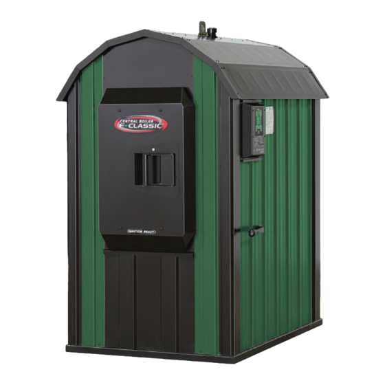
- Page 2 20502 160th Street • Greenbush, MN 56726 www.CentralBoiler.com The E-Classic 1450 outdoor hydronic heater by Central Boiler is listed by OMNI-Test Laboratories to the applicable portions of the following standards: UL 2523-2009 Solid Fuel-Fired Hydronic Heating Appliances, Water Heaters and Boilers, CAN/CSA-B366.1-M91 (R2007) Solid-Fuel-Fired Central Heating Appliance.
-
Page 3: Table Of Contents
Table of Contents INTRODUCTION ................... . . 3 Labeling and Terminology . - Page 4 Enter the web address in your browser or scan the code using any QR code reader app on your smartphone to access Central Boiler's library of information to help with installation, operation and maintenance of your Central Boiler outdoor furnace.
-
Page 5: Introduction
Furnace Installation Scenario illustration in - Measurement (G) includes two 4 ft (1.2 m) chimney sections. Planning the Location section). © 2011 Central Boiler NOTE: The outdoor furnace may be connected to an existing boiler system or hot water heating system by a qualified installer only. - Page 6 IMPORTANT PRECAUTIONARY INFORMATION The information contained on pages 4-5 appears throughout this manual. Be sure to read carefully and understand these precautions before, during and after the installation, operation and maintenance of the furnace. CAUTION WARNING This outdoor furnace is not intended to be the only Do not use this appliance if any part of the gas train source of heat.
-
Page 7: Important Precautionary Information
IMPORTANT PRECAUTIONARY INFORMATION The information contained on pages 4-5 appears throughout this manual. Be sure to read carefully and understand these precautions before, during and after the installation, operation and maintenance of the furnace. WARNING WARNING Maintain the following clearances from combustibles This heater is designed to burn natural wood only. -
Page 8: Section 1 - Outdoor Furnace Installation
SECTION 1 – OUTDOOR FURNACE INSTALLATION To ensure the E-Classic Outdoor Wood Gasification Furnace functions as designed, careful planning and proper installation are imperative. This section outlines much of the information needed to install the outdoor furnace, select water lines, install circulation pumps and connect to your existing heat emitter(s). -
Page 9: Installation Precautions
Parts are available from height above the roofs of surrounding buildings. Use an authorized Central Boiler dealer. Central Boiler Chimney Extensions when extending the The installation of a spark arrester is recommended, chimney. When only the standard eight feet (2.4 m) of... -
Page 10: General Installation Information
To prevent potential problems, do not use propylene glycol that is premixed with unknown inhibitors. Central Boiler Corrosion Inhibitor Plus (p/n 1650) is compatible with straight propylene glycol. It is important to use Corrosion Inhibitor Plus with straight propylene glycol for corrosion protection. -
Page 11: Shut-Off Valves
• You may drain the outdoor furnace to a home septic system. Central Boiler Corrosion Inhibitor Plus™ is biodegradable and can be properly treated in a residential septic system. If doing so, however, be careful not to overflow the septic system. -
Page 12: Temporary Above Ground Or Winter Installations
2. Lay the ThermoPEX assembly in the trench and buried underground, Central Boiler recommends using feed one end into the building. Apply sealant around ThermoPEX. Be sure that both the insulation and the... -
Page 13: Installing Lp Tank & Gas Piping
CAUTION WARNING Allow for expansion and contraction of the supply Once the gas supply is connected, the appliance and return lines at each end. Without an allowance and gas connection must be tested for leaks for expansion and contraction, the lines may kink before placing the appliance in operation. -
Page 14: Installing Circulation Pumps
Installing Circulation Pumps Fig. 8 The following guidelines must be adhered to when installing the circulation pump(s). NOTE: See the Hydronic Component Selection Guide (p/n 2482) for more detailed information. WARNING Maximum load of the outlet on the outdoor furnace is 10A, 120VAC, and 60Hz. A. - Page 15 4 ft. (1.2 m) min. Ground Pump must be installed Level in the hot supply line, before the heat exchanger, and may be located inside this building or on the outdoor furnace. © 2015 Central Boiler Section 1 - Outdoor Furnace Installation...
-
Page 16: Shut-Off Valves
1450 and must be installed on each set of supply and return lines or warranty can be voided. Fig. 16 NOTE: For additional thermostatic valves, or for 1-1/4" thermostatic valves, contact your Ball Valve authorized Central Boiler dealer. NOTE: thermostatic valves illustrated throughout the manual may vary from your installation. - Page 17 Section 1 - Outdoor Furnace Installation...
-
Page 18: Optional Gas-Fired Wood Ignition Burner
Return to Outdoor Furnace between the outdoor For illustration purposes only, water heater styles furnace and thermostatic may vary. valve. NOTE: See the Hydronic Component Selection © 2015 Central Boiler Guide (p/n 2482) for more detailed information. Section 1 - Outdoor Furnace Installation... -
Page 19: Existing Forced Air Installation
• The lower fitting is the inlet/hot supply from the EXISTING FORCED AIR INSTALLATION outdoor furnace and the top fitting is the outlet/ When the E-Classic Outdoor Wood Gasification Furnace return back to the outdoor furnace. is installed in conjunction with an existing forced air system, a water-to-air heat exchanger is mounted in the •... - Page 20 C is optional NOTE with batteries This configuration allows E/W1 (O/B) use of a 24-volt thermostat TI ME on older forced-air units with no control board. For illustration purposes only. © 2015 Central Boiler Section 1 - Outdoor Furnace Installation...
- Page 21 Fig. 21 Forced Air System and Water Heater Heat Exchanger Components p/n 108 Supply p/n 8200008 p/n 5926 Wood Heat Thermostat Existing p/n 1330 Thermostat Return p/n 5926 p/n 199 p/n 5349 p/n 117 p/n 255 p/n 200 p/n 5348 p/n 372 p/n 116 p/n 116...
-
Page 22: Thermostatic Controls
2. An alternative method is to install a line voltage Thermostatic Controls thermostat to control the blower on the forced air There are several methods for installing thermostatic controls for this type of installation. furnace. In this installation, a 120-volt line is run from the thermostat to the forced air furnace. -
Page 23: Heating Multiple Zones
HEATING MULTIPLE ZONES Fig. 23 A single pump and manifold may be used to heat more than one zone as long as the return water can be maintained above 150°F (66˚C). If the return water temperature can not be maintained above 150°F (66˚C), then a separate pump should be used for each zone. -
Page 24: Hydronic Installations
Installer must comply with and thermostatic valve. all applicable codes and Existing regulations. Water Hot Supply from Pump Heater on Outdoor Furnace Return to Outdoor Furnace © 2015 Central Boiler Section 1 - Outdoor Furnace Installation... -
Page 25: Pressurized Boiler System Installations
The addition of a wraparound pump with a water-to- Pressurized Boiler System Installations water heat exchanger (see Fig. 25) may increase heat Water-to-Water Heat Transfer System transfer by allowing circulation continuously through To keep the existing system pressurized, a plate the existing boiler and heat exchanger. -
Page 26: Vented System Installation
NOTE Installer must comply with all applicable codes and regulations. For illustration purposes only. Furnace, water heater and configurations will vary. © 2015 Central Boiler Section 1 - Outdoor Furnace Installation... -
Page 27: Direct Circulation Baseboard Installation
Fig. 27 and 28 illustrate direct circulation baseboard Direct Circulation Baseboard Installation installation examples. Baseboard heaters, as either the main source of heat or as supplements to forced-air or boiler applications are easily plumbed into the water lines from the outdoor furnace. -
Page 28: Radiant Floor System Installations
Barrier Insulation Insulation Slab on grade Slab Plate Ground Level Insulation Wire Poly Vapor Mesh Barrier Footing 2" Blueboard Styrofoam ® Soil/Sand is recommended (minimum ® of 1" Blueboard Styrofoam © 2013 Central Boiler Section 1 - Outdoor Furnace Installation... - Page 29 Fig. 30 Fig. 31 Section 1 - Outdoor Furnace Installation...
- Page 30 Fig. 32 Fig. 33 Section 1 - Outdoor Furnace Installation...
-
Page 31: Pool And/Or Hot Tub Heating
WARNING Pool and/or Hot Tub Heating Valves should be installed so the heat exchanger can be Do not use automotive or ethylene glycol isolated and bypassed when shock-treating or adding antifreeze in an outdoor furnace connected to chemicals to a pool or hot tub (Fig. 34). Incorrect a swimming pool heat exchanger as a damaged chemical concentrations can cause rapid corrosion to heat exchanger may cause severe personal... -
Page 32: Filling Outdoor Furnace With Water And Purging Air
Water Heater Valve #5 Hose A NOTE Supply Valve #2 Installer must comply with all applicable codes and regulations. NOTE: For illustration purposes only. Actual configuration may vary. Return Line © 2015 Central Boiler Section 1 - Outdoor Furnace Installation... - Page 33 8. Close valve #5, #1 and #2. NOTE: The sight gauge valve should always be closed except when checking water level. Water 9. Move hose A from valve #2 to valve #3. will automatically drain from the sight gauge tube. Remember that this type of valve requires 10.
-
Page 34: Section 2 - Operating Instructions
SECTION 2 – OPERATING INSTRUCTIONS • Unseasoned wood causes reduced performance, Wood Selection and Preparation For the best results, it is best to burn seasoned split wood. lower combustion rates and lower heat output. However, it may be possible to burn some unsplit wood •... -
Page 35: Importance Of Properly Seasoned Wood
© 2012 Central Boiler 2. Gasified fuel exits the bottom of the firebox the water. -
Page 36: Ash Removal Frequency
Fig. 39 CAUTION Ash Removal Frequency During the first week of operation, check the level of If the water in the outdoor furnace boils, be sure ash in the Reaction Chamber every two days. Ash needs to check the water level and restore to full. Add to be removed from the Reaction Chamber before it Corrosion Inhibitor Plus™... -
Page 37: Cold Start Firing With Power Ignition
4. The first time you fire the outdoor furnace, add Cold Start Firing with Power Ignition very dry kindling to fill the firebox to a level 1. Disconnect the heat load draw by turning off the approximately 15 inches (38 cm) from the bottom of pump(s). -
Page 38: Adding Heat Load
7. If desired, press the Wood Ignition button NOTE: During initial start-up, a considerable to increase or decrease the amount of time the gas amount of moisture from condensation will ignition burner operates. For split wood that has collect inside the firebox and heat exchanger and been seasoned 6 months or more, 5 to 8 minutes may may drip out of the Reaction Chamber door. -
Page 39: Load Wood To Reduce Condensation
2. Unlatch the firebox door; then stay as far away LOAD WOOD TO REDUCE CONDENSATION For the best results, it is best to burn seasoned split as possible as the firebox door is opened because smoke and hot gases escaping through the firebox wood less than 25% moisture by weight. - Page 40 Push cleaning rod back and forth through ash in these locations. © 2012 Central Boiler 10. Wait for 15 seconds; then slowly pull the bypass Fig. 43 door handle toward the front of the outdoor furnace and push down to close the bypass door.
- Page 41 Over time, you will become familiar with your particular conditions, and you will learn how best to load the wood so it burns down to a glowing coal bed as often as possible before reloading. ©2015 Central Boiler • 1-MAY-2015...
-
Page 42: Section 3 - Maintenance
SECTION 3 – MAINTENANCE PREVENTIVE MAINTENANCE SCHEDULE Regular maintenance and inspections can SERVICE INTERVAL help extend the life of your outdoor furnace and prevent high-cost repairs. This table is meant to serve as a general guideline until you become acquainted with how the outdoor furnace operates with your specific application. -
Page 43: Control Locations
CAUTION 3-2. Vent Cap Use only genuine Central Boiler Parts and Check that the vent cap fits loosely on the vent opening. Accessories if it ever becomes necessary to replace any component of the outdoor furnace. - Page 44 Push cleaning rod back and forth through ash in these locations. © 2012 Central Boiler 3. Remove any heavy or solidified ash. 3-4. Ash Some ash, but not more than three inches, on the sides and bottom of the firebox is necessary for the proper CAUTION operation of the outdoor furnace (as shown in Fig.
- Page 45 CAUTION Fig. 48 Be sure to turn off the FireStar controller before doing this procedure. 2. Remove the top rear panels, insulation and the access covers to the heat exchangers. 3. Open the rear access door; then open the Reaction Chamber door (see Fig.
- Page 46 6. Close the Reaction Chamber door; then close the Fig. 53 rear access door. 7. Replace the access covers, insulation and top rear panels. 8. Press the Power button on the FireStar controller to turn it on. 3-8. Reaction Chamber 1.
- Page 47 Complete Firebox Pull Out Cleaning Procedures. to Remove NOTE: The secondary air charge tube and © 2012 Central Boiler refractory are wear items. 3-11. Combustion Air Fan 1. Disconnect power to the outdoor furnace. Fig. 57...
-
Page 48: Burner Maintenance
9/16" hex head. optional gas-fi red wood ignition burner, contact your 1. Remove the 3/8" NF-24 bolt and washer securing Central Boiler dealer or qualifi ed service technician. the bypass handle to the side of the furnace. 3-14. Primary Air Elbow 2. - Page 49 Chimney Tee Bypass Door Area Heat Exchanger Reaction Chamber © 2012 Central Boiler 3. Firebox 1. Using a shovel, remove as much ash as possible. NOTE: Refer to Fig. 60 and clean the areas identified in the order shown. For each area in the 2.
- Page 50 4. Inspect the surfaces of the firebox for any signs of Fig. 63 corrosion. Use a wire brush to clean if needed. 4. Chimney Tee 1. Remove the chimney inspection cover. Clean the chimney outlet and chimney of excessive ash or deposits.
-
Page 51: Water Quality And Maintenance
1. Slide each of the four corner sections up and remove is controlling the quality of the water in the outdoor furnace. Central Boiler supplies a pH test strip and a any ash or deposits from behind them. With access nitrite test kit with each new outdoor furnace. -
Page 52: Corrosion Inhibitor Plus™ And Initial Treatment
Corrosion Inhibitor Plus™ and Initial WARNING Treatment Central Boiler Corrosion Inhibitor Plus™ (p/n 1650) Sulfuric Acid is a corrosive acid. Handle carefully. gives optimum protection when it is used to initially Carefully read and follow precautions on test treat the water and is then maintained at proper levels. -
Page 53: Post Heating Season Maintenance
NOTE: If there is a leak in the system or if the Flushing the System If the system water is brown or orange, it is an indication outdoor furnace loses water from boiling the Corrosion Inhibitor Plus level has not been frequently, the problem should be identified and maintained and corrosion is present in the water jacket. -
Page 54: Section 4 - Serviceable Items
Labor is not covered. 6. Scrape the face and surface area of the door frame to NOTE: Use only genuine Central Boiler parts remove any deposits. and accessories if it ever becomes necessary to replace any component on the outdoor furnace. -
Page 55: Reaction Chamber Door Seal
1. Measure the distance from the edge of the bearing 5. Starting at the center of the hinge side of the Reaction assembly mounting brackets to the bearing Chamber door, insert the new 3/4" door seal rope assemblies to serve as a reference point for into the groove, pressing it firmly into the bead of subsequent adjustments. -
Page 56: Bypass Door Rope
2. Open the airbox cover located at the rear of the 8. Working inside the firebox, install the four new nuts. outdoor furnace. SOLENOID 3. Disconnect the wires from each of the solenoids, 1. Disconnect power to the outdoor furnace. disconnect the fan harness and disconnect the push- wire connector from the transformer. -
Page 57: Secondary Air Charge Tube And Refractory Modules
THERMOCOUPLE Fig. 72 1. Disconnect power to the outdoor furnace. WARNING Do not proceed without testing that power is disconnected. Make sure the power cannot be reconnected while replacing the thermocouple 2. Open the airbox cover located at the rear of the outdoor furnace. -
Page 58: Section 5 - Troubleshooting
SECTION 5 – TROUBLESHOOTING GENERAL TROUBLESHOOTING Fig. 75 INFORMATION The E-Classic operates differently than other types of wood-burning appliances. Understanding how the E-Classic operates will help you to quickly identify and solve many commonly asked questions. Be sure to read thoroughly and understand Section 2 – Operating Instructions. - Page 59 2. Bypass door not operated correctly - The function Fig. 76 of the bypass door is to prevent the buildup of gases in the firebox in certain situations by venting them out through the chimney. An example is when adding wood to the outdoor furnace with a very hot bed of coals or a raging fire in the firebox.
- Page 60 Check the water level at the sight gauge and, if necessary, add water according to the Water Quality and Maintenance section. If adding water does not correct the problem, contact your Central Boiler dealer. 10. Low water temperature for too long a period of...
- Page 61 10. Optional gas-fired wood ignition not operating - Fig. 79 Check that the supply valve is turned on, the propane tank is not empty and that Wood Auto Relight is enabled. Refer to the gas-fired wood ignition manual for more information. C.
- Page 62 NOTE: If the outdoor furnace loses water from amount of heat output. If this condition is suspected, boiling, the problem should be identified and contact your Central Boiler dealer. repaired immediately. Under normal operation, little or no water needs to be added. Adding 13.
- Page 63 Make sure the pump motor is installed in a horizontal 4. High heat demand - Concrete slabs (with radiant position. The junction box must not be located below heat) that are poorly insulated or are exposed to water the pump motor (see Fig. 82). If necessary, remove or cold outside temperatures will require increased the four screws and rotate the pump body.
- Page 64 If you are unsure how to proceed, contact your Central Boiler dealer. 2. Bypass door not sealing properly - Make sure nothing is obstructing the bypass door, preventing 1.
-
Page 65: Section 6 - General Information
SECTION 6 – GENERAL INFORMATION Make note of these precautionary statements also found on the furnace. CAUTION If this configuration is used and water is drained from the furnace, remove the plug from the unused supply port to prevent damage from water freezing. -
Page 66: E-Classic 1450 Wiring Diagram
E-CLASSIC 1450 WIRING DIAGRAM Section 6 - General Information... -
Page 67: E-Classic 1450 Wiring Diagram - Optional Power Ignition
E-CLASSIC 1450 WIRING DIAGRAM - OPTIONAL POWER IGNITION Section 6 - General Information... -
Page 68: Glossary
A device that transfers heat from one water system to another without PLENUM mixing the water in the two systems. Central Boiler supplies plate-type The large duct area immediately before or after the forced-air furnace. and shell and tube type water to water heat exchangers. - Page 69 NOTES...
- Page 70 NOTES...
- Page 71 NOTES...
-
Page 72: 1-Year Limited Warranty
If a defect exists, at its option Central Boiler will (1) repair the defective part at no charge, using new or refurbished replacement parts, (2) exchange the furnace with a comparable model furnace that is new or which has been manufactured from new or serviceable used parts and is at least functionally equivalent to the original furnace, or (3) refund the purchase price.
Need help?
Do you have a question about the e-Classic 1450 IR and is the answer not in the manual?
Questions and answers