
Related Manuals for Central Boiler MaXIM M255 PE


Summary of Contents for Central Boiler MaXIM M255 PE
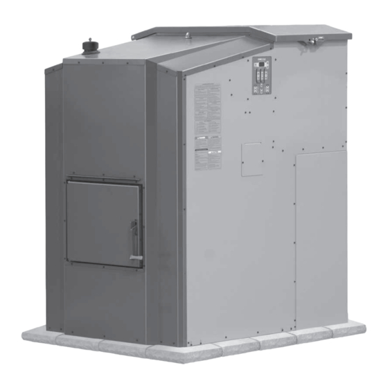
- Page 1 WOOD PELLET FURNACE OWNER’S MANUAL M255 P; M255 PE Tested & Portland Listed By Oregon USA Save This Manual For Future Reference OMNI-Test Laboratories, Inc. 117-O-24-2 (p/n 9000311 - REV. A) - 15-MAY-2015...
- Page 2 3. Persons operating this hydronic heater are responsible for operation of the hydronic heater so as not to cause a condition of air pollution as defined in 310 CMR 7.01(1). For parts and accessories, service or repairs, call your authorized Central Boiler dealer or heating contractor. Record the information below for future reference.
-
Page 3: Table Of Contents
Table of Contents INTRODUCTION ..................4 SECTION 1 –... -
Page 4: Introduction
INTRODUCTION Foreword Labeling and Terminology The outdoor furnace and this owner's manual use the This manual is to be used as a guideline for the installation, operation and maintenance of the Maxim following terms and symbols to bring attention to the Wood Pellet Furnace. - Page 5 IMPORTANT PRECAUTIONARY INFORMATION The information contained on this page appears throughout this manual. Be sure to read carefully and understand these precautions before, during and after the installation, operation and maintenance of the furnace. WARNING WARNING This outdoor furnace is not intended to be the Maintain the following clearances from only source of heat.
- Page 6 IMPORTANT PRECAUTIONARY INFORMATION The information contained on this page appears throughout this manual. Be sure to read carefully and understand these precautions before, during and after the installation, operation and maintenance of the furnace. WARNING WARNING Use only those listed fuels recommended by Allow the outdoor furnace to thoroughly cool the manufacturer of your unit.
-
Page 7: Section 1 - General Information
NOTE: The Maxim Furnace includes two 4-foot (1.2-meter) ASHT 6" in diameter chimney sections listed to UL103HT. For chimney sections or chimney replacement, use only genuine Central Boiler chimney components. Parts are available from an authorized Central Boiler dealer. Section 1 - General Information... -
Page 8: Potable Water
Auger Kit (p/n 9454) are also available for other To aid in protecting the system from corrosion, it is applications. The auxiliary augers can also be used with imperative to add Central Boiler Corrosion Inhibitor larger external bins. Plus™ (p/n 1650). When initially filling the system (see... -
Page 9: Section 2 - Location And Foundation
SECTION 2 – LOCATION AND FOUNDATION ❑ If the ground at the location is unstable or subject Selecting a Location To ensure the Maxim Furnace functions as designed, to frost heaving, consider installing 2" closed-cell careful planning and proper installation are imperative. insulation under the front portion of the concrete slab the outdoor furnace will be installed on, and Be sure to read carefully and observe all of the... -
Page 10: Leveling The Outdoor Furnace
Foundation may consist of concrete, crushed rock, or patio blocks. © 2014 Central Boiler To install the outdoor furnace on a concrete foundation, Leveling the Outdoor Furnace refer to Fig. -
Page 11: Clearances
• The foundation must be noncombustible Shim (Shown in black) Foundation © 2014 Central Boiler 4. Use shims as necessary under the outdoor furnace in the locations shown until the procedure in Step 3 indicates that the back of the transition box is slightly higher than the front. -
Page 12: Section 3 - Electrical
SECTION 3 – ELECTRICAL NOTE: Any electrical installation should be Fig. 9 done by a qualified installer in accordance with applicable codes. Ground Rod The outdoor furnace must be electrically bonded to ground in accordance with the requirements of the authority having jurisdiction or, in absence of such requirements, with the National Electrical Code, ANSI/ NFPA 70 and/or the Canadian Electrical Code Part 1,... -
Page 13: Section 4 - Gas Supply Connection (P Models) And Ignitor Operation
SECTION 4 – GAS SUPPLY CONNECTION (P Models) AND IGNITOR OPERATION Temperatures below 0˚F (-18˚C) also will cause small Gas Supply Connection The M255 P is designed so that a one-pound propane LP gas regulators to work incorrectly, outputting gas cylinder may be connected to the gas ignitor. -
Page 14: Ignition Sequence - P Models
Ignition Sequence - P Models Ignition Sequence - PE Models The ignition sequence is a series of steps that The ignition sequence follows a control logic to ensure automatically occur to ensure the gas ignitor starts safe and effective ignition. The ignition sequence is as properly before the system begins to operate. -
Page 15: Section 5 - Chimney
If extensions are added to the standard eight feet (2.4 m) of height above the roofs of surrounding buildings. Use chimney, the chimney should be reinforced appropriately. Central Boiler Chimney Extensions when extending Fig. 15 shows chimney support recommendations when the chimney. When only the standard eight feet (2.4 m) three or more sections are used. -
Page 16: Chimney Draft
4. Objects like buildings and trees in close proximity or Chimney Draft nearby terrain (e.g., hills, valleys, etc.) can adversely Proper draft is necessary for the Maxim to operate optimally. Draft occurs when the temperature in the affect air flow in the chimney (see Fig. 16). Adding chimney is high enough and/or the chimney is high chimney sections may overcome these factors. -
Page 17: Section 6 - System Installation
Determine the configuration of the supply and return lines from the outdoor furnace to where the supply and return lines will connect to the existing heating system. Central Boiler recommends using the ThermoPEX ® piping system. ThermoPEX is a fully assembled, pre-insulated piping system consisting of two 1"... -
Page 18: Digging The Trench
Digging the Trench NOTE: The base on the back of the outdoor furnace is removable if necessary for connecting WARNING the supply and return lines to the outdoor furnace. Before digging, be sure to call for utility locator Fig. 19 service. -
Page 19: Circulation Pumps
CIRCULATION PUMPS Fig. 22 NOTE: The direction of water fl ow is very important for the proper operation of the outdoor furnace. Installing a swing check valve in the return line can prevent possible reverse fl ow. Water Flow For a single building using a water-to-air heat exchanger system with a domestic water heater, the direction of water fl ow must go from the hot outlet on the outdoor furnace to the lower side fi tting of the domestic water... - Page 20 The Taco 014 is a high flow, high head pressure pump Fig. 24 that requires an adequate amount of head pressure on the inlet side to prevent cavitation. Therefore, a Taco 014 may need to be mounted lower near the base of the furnace, and on the 1-1/4"...
-
Page 21: Shut-Off Valves
Return to and may be located Outdoor Furnace inside this building © 2015 Central Boiler Shut-Off Valves Shut-off valves should be installed on both sides of each pump so if it becomes necessary to repair or replace the pump, the pump can be isolated. -
Page 22: Maxim Thermostatic Valve - How It Works
MAXIM THERMOSTATIC VALVE - HOW IT WORKS NOTE: With higher heat loads, it may be necessary to change the water temperature setpoint on the FireStar controller to be no less than 185˚F. NOTE: When the thermostatic valve allows a trace flow, enough water will pass through for the backup indoor heating system to backfeed heat to the outdoor furnace and water lines, protecting against freezing. -
Page 23: Purging Air From The System - Manual Air Bleeders
Thermostatic Valve A pump must be installed in the hot supply line Return to Outdoor Furnace between the outdoor For illustration purposes only, water heater styles furnace and thermostatic may vary. valve. © 2015 Central Boiler Section 6 - System Installation... -
Page 24: Existing Forced Air Installation
• The lower fitting is the inlet/hot supply from the EXISTING FORCED AIR INSTALLATION outdoor furnace and the top fitting is the outlet/ When the Maxim is installed in conjunction with an return back to the outdoor furnace. existing forced air system, a water-to-air heat exchanger is mounted in the plenum or duct work of the existing •... - Page 25 24-Volt Thermostat C is optional NOTE with batteries This configuration allows E/W1 (O/B) use of a 24-volt thermostat E PR on older forced-air units with no control board. For illustration purposes only. © 2015 Central Boiler Section 6 - System Installation...
- Page 26 NOTE p/n 117 p/n 2443 furnace water temperature p/n 199 p/n 116 Installer must comply with all applicable setpoint should be set at p/n 5349 codes and regulations. 185˚F minimum. p/n 5348 2013 Central Boiler Section 6 - System Installation...
-
Page 27: Thermostatic Controls
2. An alternative method is to install a line voltage Thermostatic Controls There are several methods for installing thermostatic thermostat to control the blower on the forced air furnace. In this installation, a 120-volt wire is run controls for this type of installation. from the thermostat to the forced air furnace. -
Page 28: Heating Multiple Zones Or Buildings
The Maxim offers two sets of outlets (for up to two HEATING MULTIPLE ZONES OR BUILDINGS A single pump and manifold may be used to heat zones or buildings without the need for manifolds) for mounting up to two pumps. Fig. 35 illustrates one more than one zone as long as the return water can be maintained above 150°F (66˚C). -
Page 29: Hydronic Installations
Installer must comply with and thermostatic valve. all applicable codes and Existing regulations. Water Hot Supply from Pump Heater on Outdoor Furnace Return to Outdoor Furnace © 2015 Central Boiler Section 6 - System Installation... -
Page 30: Pressurized Water System Installations
The addition of a wraparound pump with a water- Pressurized Water System Installations to-water heat exchanger (see Fig. 37) may increase Water-to-Water Heat Transfer System heat transfer by allowing circulation continuously To keep the existing system pressurized, a plate through the existing boiler and heat exchanger. This exchanger or tube &... -
Page 31: Vented System Installation
Auto Relight Enabled Note A pump must be installed in the hot supply line between the outdoor furnace and thermostatic valve. Note Installer must comply with all applicable codes and regulations. © 2013 Central Boiler Section 6 - System Installation... -
Page 32: Direct Circulation Baseboard Installation
Refer to Fig. 39 and 40 for proper plumbing methods. Direct Circulation Baseboard Installation Baseboard heaters, as either the main source of heat or as supplements to forced-air or boiler applications are easily plumbed into the water lines from the outdoor furnace. -
Page 33: Radiant Floor System Installations
Soil/Sand Barrier Insulation Insulation Slab on grade Slab Plate Ground Level Insulation Wire Poly Vapor Mesh Barrier Footing ® 2" Blueboard Styrofoam Soil/Sand is recommended (minimum of 1" Blueboard Styrofoam ® © 2013 Central Boiler Section 6 - System Installation... - Page 34 Fig. 42 Fig. 43 Section 6 - System Installation...
- Page 35 Fig. 44 Fig. 45 Section 6 - System Installation...
-
Page 36: Pool And/Or Hot Tub Heating
Pool and/or Hot Tub Heating WARNING Valves should be installed so the heat exchanger can be isolated and bypassed when shock-treating or adding Do not use automotive or ethylene glycol chemicals to a pool or hot tub (Fig. 46). Incorrect antifreeze in an outdoor furnace connected to a swimming pool heat exchanger as a damaged chemical concentrations can cause rapid corrosion to... -
Page 37: Section 7 - Filling System With Water And Purging Air
Hose A NOTE Supply Valve #2 Installer must comply with all applicable codes and regulations. NOTE: For illustration purposes only. Actual configuration may vary. Return Line © 2015 Central Boiler Section 7 - Filling System with Water and Purging Air... - Page 38 1. Connect the male end of garden hose A to valve #1 NOTE: The valves on the hot supply and return using the backflow preventer and two 3/4" female lines of the outdoor furnace, and valves #4 and hose x 3/4" male pipe adapters (p/n 4928). Connect #5 should all be open, allowing the pump to the female end of the garden hose to valve #2.
-
Page 39: Section 8 - Operating Instructions
If this condition exists, inspect the burner auger and clean or replace WARNING as necessary. If condition persists contact your Central Boiler dealer for more information. Do not store fuel within the outdoor furnace installation clearances or within the spaces Fig. 50 required for fueling, ash removal and other routine maintenance operations. -
Page 40: Filling The Hopper
Smoke in Hopper Fig. 51 How air flows through the furnace is an important part of optimal operation. Smoke in the hopper is an indication that the air flow through the furnace is restricted, obstructed or different than it should be. CAUTION Operating for extended periods of time with air 4. -
Page 41: Section 9 - Routine Maintenance
SECTION 9 – ROUTINE MAINTENANCE PREVENTIVE MAINTENANCE SCHEDULE Regular maintenance and inspections can SERVICE INTERVAL help extend the life of your outdoor furnace and prevent high-cost repairs. This table is meant to serve as a general guideline until you become acquainted with how the outdoor furnace operates with your specific application. -
Page 42: Routine Maintenance
1. Do not allow ash in the burn chamber to accumulate CAUTION over the aerator as shown in Fig. 56. Use the Use only genuine Central Boiler Parts and cleaning rod provided to pull the ash forward to the Accessories if it ever becomes necessary to ash collection area. -
Page 43: 9.4 Gaskets
NOTE: Replacement gaskets for the furnace door, chimney transition cover and hopper are available from authorized Central Boiler dealers. Fig. 59 Remove deposits by scraping with the cleaning rod provided with your outdoor furnace. Use the cleaning... -
Page 44: 9.6 Aerator And Burn Chamber
Clean ash from inside the burn chamber. Fig. 62 3. Scrape carbon deposits from the auger, the surfaces of the aerator and the burn chamber. Maxim M255 PE models CAUTION Ignitor Do not strike the aerator or burn chamber with a hammer or other hard item to remove deposits. -
Page 45: 9.7 Door And Hopper
Illustration shows one possible configuration for Inspection thermal valve. Window Installations may vary. Discharge Tube Burner Auger Motor Snap Disc Burner Auger Shaft Red Cap Thermal Valve (Insulated) Motor Mount Plate © 2013 Central Boiler Section 9 - Routine Maintenance... - Page 46 2. Remove the access panels from the back corner of Clean the Affected Areas the furnace and set aside. 1. Inspect the bottom of the hopper and remove any wet fuel from the opening at the bottom. 3. If a one-pound propane cylinder is threaded onto the regulator on the gas valve, remove it.
-
Page 47: Test Thermal Valve
4. Push down on the red cap of the thermal valve and Fig. 65 run a small amount of water through the valve to Top View of Maxim Hopper make sure it is operating properly. 5. Connect the silicone tubing to the thermal valve Transfer making sure not to kink the silicone tubing. -
Page 48: Water Quality And Maintenance
An important part of outdoor furnace maintenance is controlling the quality of the water in the furnace. Central Boiler supplies a pH test strip and a nitrite test kit with each new outdoor furnace. Water Test Kits and Test Results It is very important to keep record of water test results (include the date, pH and nitrite level). - Page 49 Corrosion Inhibitor Plus™ and Initial Treatment Central Boiler Corrosion Inhibitor Plus™ (p/n 1650) gives optimum protection when it is used to initially treat the water and is then maintained at proper levels. The initial nitrite level target is 20 drops by nitrite test, but 20 to 30 drops is acceptable.
-
Page 50: Post Heating Season Maintenance
7. Do not exceed treatment of higher than 30 drops 2. Remove the aerator and burn chamber; inspect and by the nitrite test. If the test requires more than 30 clean as explained in section 9.7 Aerator and Burn drops, dilute the water by draining water from the Chamber. -
Page 51: Section 10 - Troubleshooting
14. Supply and return lines uninsulated - Uninsulated Contact your Central Boiler dealer for assistance. supply and return lines in areas that are not intended 4. Circulation valve(s) closed - Be sure all valves in to be heated (unheated crawl spaces, under mobile the system are open. - Page 52 3. Water is not circulating - The pump should run E. BURNING AN EXCESSIVE AMOUNT OF and water should circulate continuously through the FUEL. supply and return lines to keep water temperature 1. High volume water heating - High volume water uniform in the outdoor furnace.
- Page 53 If you are unsure how to proceed, contact your Central Boiler dealer. 1. Water temperature is too low - If the heat load in the system is too large, the water in the system will not reach high enough temperatures and corrosion can occur.
- Page 54 5. Chimney dirty or obstructed - Inspect the f. Check the water level periodically during the next 48 hours (the water level may drop slightly as the chimney transition and chimney for obstructions or water cools). restrictions and clean if necessary. g.
- Page 55 300˚F (149˚C), the thermocouple will to remove, oven cleaner may be used to soften the need to be replaced. Contact your Central Boiler deposits. Inspect for cracked insulation, damage or dealer.
-
Page 56: Section 11 - Decals
Load 10 Amp White (Neutral) NOTICE Green (Ground) Ground Rod Kit (p/n 6593) Recommended © 2006 Central Boiler p/n 5071 DO NOT operate this appliance with this panel removed. NOTICE p/n 4125 DO NOT alter this equipment in any way. -
Page 57: Section 12 - Wiring Diagrams
SECTION 12 – WIRING DIAGRAMS Maxim M255P Wiring Diagram ref. Color Description Voltage Color Description Voltage Color Description Voltage Orange Burner auger 120V Violet Fan control 5 VDC 12 Yellow/Black Spare thermocouple Yellow Gas burner transformer 120V Green/Black Low voltage ground 5 VDC 13 Red/Black Thermocouple ground... -
Page 58: Wiring Diagram
SECTION 12 – WIRING DIAGRAMS Maxim M255 PE Models Water Level Main Harness Sensor Wiring Diagram Connector Pin Order Control Panel Electric Ignition Assembly BLU/ GRN/ Main Water Temperature 16GA 16GA 16GA 16GA Harness Sensor GRN/ Screw-on High Limit 16GA... -
Page 59: Section 13 - Parts Listings
6180 9787 9146 9105 3100597 9296 9125-021(T) 5349 9332 1336 9125-202 (G) Color Code Reference 9297 (T) = Terra Brown/Taupe (G) = Green/Olive Gray © 2013 Central Boiler *Kit includes all gaskets, bushings and plates Section 13 - Parts Listing... - Page 60 Central Boiler is not liable for damage or repairs required as a consequence of faulty installations or applications by others or any event of force majeure. Central Boiler is not liable for incidents or accidents which can be prevented by the owner or that occur from the operation of the outdoor furnace.
Need help?
Do you have a question about the MaXIM M255 PE and is the answer not in the manual?
Questions and answers