
Related Manuals for Central Boiler Maxim M255 PE


Summary of Contents for Central Boiler Maxim M255 PE
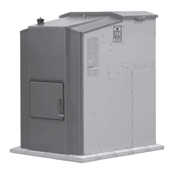
- Page 1 WOOD PELLET FURNACE OWNER’S MANUAL M255 PE Tested & Portland Listed By Oregon USA Save This Manual OMNI-Test Laboratories, Inc. For Future Reference 0117PS024S 0117PS024E (p/n 9000838 - REV. A)
- Page 2 3. Persons operating this hydronic heater are responsible for operation of the hydronic heater so as not to cause a condition of air pollution as defined in 310 CMR 7.01(1). For parts and accessories, service or repairs, call your authorized Central Boiler dealer or heating contractor. Record the information below for future reference.
-
Page 3: Table Of Contents
Table of Contents INTRODUCTION ..................4 SECTION 1 –... -
Page 4: Introduction
INTRODUCTION Foreword Labeling and Terminology The outdoor furnace and this owner's manual use the This manual is to be used as a guideline for the installation, operation and maintenance of the Maxim following terms and symbols to bring attention to the Wood Pellet Furnace. - Page 5 WARNING construction that contains combustible materials © 2008 Central Boiler Do not allow combustible materials (straw, hay as part of the structure or configuration. The or wood) near the outdoor furnace. Keep the chimney is not intended or safety tested to perimeter of the outdoor furnace clear and clean.
- Page 6 IMPORTANT PRECAUTIONARY INFORMATION The information contained on this page appears throughout this manual. Be sure to read carefully and understand these precautions before, during and after the installation, operation and maintenance of the furnace. WARNING CAUTION Burn premium quality wood pellets only. Always wear the appropriate personal protective gear when cleaning ash from the firebox.
-
Page 7: Section 1 - General Information
NOTE: The Maxim Furnace includes two 4-foot (1.2-meter) ASHT 6" in diameter chimney sections listed to UL103HT. For chimney sections or chimney replacement, use only genuine Central Boiler chimney components. Parts are available from an authorized Central Boiler dealer. Section 1 - General Information... -
Page 8: Options For Increasing Fuel Storage
Options for Increasing Fuel Storage NOTE: If using antifreeze, test the pH and Moly An optional 48-Bushel Hopper is available (p/n 9660 levels once each month. If the bacterial issues or 9760) for increasing fuel storage. This hopper can occur, the pH will decrease. be positioned to the side of the furnace using a 5-1/2' NOTE: Be sure to adhere to all warnings and Auxiliary Auger Kit (p/n 9440). -
Page 9: Section 2 - Location And Foundation
SECTION 2 – LOCATION AND FOUNDATION ❑ If the ground at the location is unstable or subject Selecting a Location To ensure the Maxim Furnace functions as designed, to frost heaving, consider installing 2" closed-cell careful planning and proper installation are imperative. insulation under the front portion of the concrete slab the outdoor furnace will be installed on, and Be sure to read carefully and observe all of the... -
Page 10: Leveling The Outdoor Furnace
Fig. 6 Maxim Furnace Base Dimensions Optional 48-Bushel Furnace Base Dimensions Hopper with Furnace Base Dimensions 48" 12.5" Optional 48-Bushel 12" Fuel Hopper 48" 49.5" Maxim 12" Furnace 37" 12" 49.5" Maxim Front Furnace 37" 34" Front NOTE 34" Furnace must be installed on a noncombustible CAUTION surface or foundation that incorporates an enclosure that will prevent supply and return lines from possible... -
Page 11: Clearances
3. Place a level on the back of the burner auger motor Clearances as shown in Fig. 7. The back of the transition box NOTE: Clearance to combustibles from the should be slightly higher than the front, indicated chimney transition box is 8" (20 cm); HOWEVER, when the level is vertical and there is a small gap if installing with the back of the outdoor furnace (from 1/16"... -
Page 12: Section 3 - Electrical
SECTION 3 – ELECTRICAL NOTE: Any electrical installation should be Fig. 9 done by a qualified installer in accordance with Side View of Pump applicable codes. Access Area Ground Rod NOTE: Incoming The outdoor furnace must be electrically bonded to power, Handy box, ground in accordance with the requirements of the Ground... -
Page 13: Section 4 - Ignitor Operation
SECTION 4 – IGNITOR OPERATION Ignition Sequence The ignition sequence follows a control logic to ensure 4. The electric ignitor will warm up and heat the air safe and effective ignition. The ignition sequence is as blowing across it into the burn chamber. follow: 5. -
Page 14: Section 5 - Chimney
If extensions are added to the standard eight feet (2.4 m) of height above the roofs of surrounding buildings. Use chimney, the chimney should be reinforced appropriately. Central Boiler Chimney Extensions when extending Fig. 15 shows chimney support recommendations when the chimney. When only the standard eight feet (2.4 m) three or more sections are used. -
Page 15: Chimney Draft
4. Objects like buildings and trees in close proximity or Chimney Draft nearby terrain (e.g., hills, valleys, etc.) can adversely Proper draft is necessary for the Maxim to operate optimally. Draft occurs when the temperature in the affect air flow in the chimney (see Fig. 16). Adding chimney is high enough and/or the chimney is high chimney sections may overcome these factors. -
Page 16: Section 6 - System Installation
Determine the configuration of the supply and return lines from the outdoor furnace to where the supply and return lines will connect to the existing heating system. Central Boiler recommends using the ThermoPEX ® piping system. ThermoPEX is a fully assembled, pre-insulated piping system consisting of two 1"... -
Page 17: Digging The Trench
Digging the Trench NOTE: The base on the back of the outdoor furnace is removable if necessary for connecting WARNING the supply and return lines to the outdoor furnace. Before digging, be sure to call for utility locator Fig. 19 service. -
Page 18: Circulation Pumps
CIRCULATION PUMPS Fig. 22 Side View Rear View NOTE: The direction of water flow is very important for the proper operation of the outdoor furnace. Installing a swing check valve in the return line can prevent possible reverse flow. Water Flow For a single building using a water-to-air heat exchanger system with a domestic water heater, the direction of water flow must go from the hot outlet on the outdoor... - Page 19 The Taco 014 is a high flow, high head pressure pump Fig. 24 that requires an adequate amount of head pressure on the inlet side to prevent cavitation. Therefore, a Taco Side View Rear View 014 may need to be mounted lower near the base of the furnace, and on the 1-1/4"...
-
Page 20: Shut-Off Valves
Installing the circulation pump(s) at the outdoor furnace Optional Thermostatic Valve is recommended, but required if the building being NOTE: thermostatic valves illustrated heated is higher than the outdoor furnace or if there is a throughout the manual may vary from your large rise in the water lines between the outdoor furnace installation. - Page 21 OPTIONAL THERMOSTATIC VALVE - HOW IT WORKS NOTE: With higher heat loads, it may be necessary to change the water temperature setpoint on the FireStar controller to be no less than 185˚F. NOTE: When the thermostatic valve allows a trace flow, enough water will pass through for the backup indoor heating system to backfeed heat to the outdoor furnace and water lines, protecting against freezing.
-
Page 22: Purging Air From The System - Manual Air Bleeders
Purging Air from the System - Manual Air WATER HEATER INSTALLATION Bleeders WARNING Manual air bleeders may be installed in the high points DO NOT disable or remove any safety reliefs or of the water lines where air may get trapped and cause controls. -
Page 23: Existing Forced Air Installation
• The lower fitting is the inlet/hot supply from the EXISTING FORCED AIR INSTALLATION outdoor furnace and the top fitting is the outlet/ When the Maxim is installed in conjunction with an return back to the outdoor furnace. existing forced air system, a water-to-air heat exchanger is mounted in the plenum or duct work of the existing •... - Page 24 Fig. 32 WATER-TO-AIR HEAT EXCHANGER AND WATER HEATER SYSTEM NOTE: A certified electrician must perform the electrical installation. Thermostatic Mixing Valve Heat Exchanger This horizontal assembly must not exceed a height of 4 inches (10 cm) above top Hot Supply of water heater.
- Page 25 Fig. 33 Forced Air Heating and Water Heater System p/n 108 Supply p/n 8200008 p/n 5926 Wood Heat Thermostat Existing p/n 1330 Thermostat Return p/n 5926 p/n 199 p/n 5349 p/n 117 p/n 255 p/n 200 p/n 5348 p/n 372 p/n 116 p/n 116 p/n 591...
-
Page 26: Thermostatic Controls
2. An alternative method is to install a line voltage Thermostatic Controls There are several methods for installing thermostatic thermostat to control the blower on the forced air furnace. In this installation, a 120-volt wire is run controls for this type of installation. from the thermostat to the forced air furnace. -
Page 27: Heating Multiple Zones Or Buildings
The Maxim offers two sets of outlets (for up to two HEATING MULTIPLE ZONES OR BUILDINGS A single pump and manifold may be used to heat zones or buildings without the need for manifolds) for mounting up to two pumps. Fig. 35 illustrates one more than one zone as long as the return water can be maintained above 150°F (66˚C). -
Page 28: Hydronic Installations
If the existing heating system is marginal or designed to HYDRONIC INSTALLATIONS operate with water temperatures above 165°F (74˚C), NOTE: It is recommended that the circulation there are alternative installation procedures that will pump in all hydronic systems be located in the make the existing system work very well with the hot supply line, not in the return line (see Fig. -
Page 29: Pressurized Water System Installations
The addition of a wraparound pump with a water- Pressurized Water System Installations to-water heat exchanger (see Fig. 37) may increase Water-to-Water Heat Transfer System heat transfer by allowing circulation continuously To keep the existing system pressurized, a plate through the existing boiler and heat exchanger. This exchanger or tube &... -
Page 30: Vented System Installation
It is very important to eliminate all air and water leaks Vented System Installation The Maxim may be connected directly into an existing (valve packings, bleeders, etc.) and purge all air from the existing system. hot water system, changing it to an atmospheric vented system. -
Page 31: Direct Circulation Baseboard Installation
Refer to Fig. 39 and 40 for proper plumbing methods. Direct Circulation Baseboard Installation Baseboard heaters, as either the main source of heat or as supplements to forced-air or boiler applications are easily plumbed into the water lines from the outdoor furnace. -
Page 32: Radiant Floor System Installations
Soil/Sand Barrier Insulation Insulation Slab on grade Slab Plate Ground Level Insulation Wire Poly Vapor Mesh Barrier Footing ® 2" Blueboard Styrofoam Soil/Sand is recommended (minimum ® of 1" Blueboard Styrofoam © 2013 Central Boiler Section 6 - System Installation... - Page 33 Fig. 42 Multi Zone In-Floor NOTE p/n 8200008 ON / OFF switch must be in the "ON" position Hot Supply from Pump on 24-Volt Thermostat for this install. Outdoor Furnace R W X X R C View TIME PRGM RUN HOLD SYSTEM ON AUTO COOL...
- Page 34 Fig. 44 Radiant Heat Single Zone Qty p/n Description Qty p/n Description 90º, 1" Street Elbow 5800011 007 Zoning Pump 3/4" Close Nipple Power Supply Cord, 32" 90º, Brass, 3/4" Street Elbow Water-to-Water Heat Exchanger NOTE This horizontal assembly 1" Sweat Tee 1329 Three Branch Valved Manifold must not exceed a height...
-
Page 35: Pool And/Or Hot Tub Heating
Pool and/or Hot Tub Heating WARNING Valves should be installed so the heat exchanger can be isolated and bypassed when shock-treating or adding Do not use automotive or ethylene glycol chemicals to a pool or hot tub (Fig. 46). Incorrect antifreeze in an outdoor furnace connected to chemical concentrations can cause rapid corrosion to a swimming pool heat exchanger as a damaged... -
Page 36: Section 7 - Filling System With Water And Purging Air
SECTION 7 – FILLING SYSTEM WITH WATER AND PURGING AIR Before firing the outdoor furnace for the first time, FILLING OUTDOOR FURNACE WITH WATER perform the following important steps: AND PURGING AIR NOTE: The items referred to in this procedure 1. - Page 37 NOTE: Skip to Step 12 if your system does not fittings and hose ends for any signs of leakage; repair © 2008 Central Boiler have a seasonal manual bypass valve (valve #6 as necessary. It may be possible to stop a very slow shown in Fig.
-
Page 38: Section 8 - Operating Instructions
SECTION 8 – OPERATING INSTRUCTIONS Fuel Selection Filling the Hopper Use only premium quality wood pellets. Open the hopper lid (Fig. 50) and add fuel. After filling, make sure the hopper lid is securely closed to prevent Feed rates and safe operation are not warranted moisture from entering the hopper. -
Page 39: Firestar Controller
If this condition exists, Fig. 54 inspect the burner auger and clean or replace as necessary. If condition persists contact your Central Boiler dealer for more information. Vent Cap Must Fig. 53 Fit Loosely 4. All cover plates, enclosures and guards must be secured at all times except during maintenance, inspection, and servicing. -
Page 40: Smoke In Hopper
Smoke in Hopper How air flows through the furnace is an important part of optimal operation. Smoke in the hopper is an indication that the air flow through the furnace is restricted, obstructed or different than it should be. CAUTION Operating for extended periods of time with air flow through the furnace restricted (i.e., smoke in the hopper) can damage components in the... -
Page 41: Section 9 - Routine Maintenance
SECTION 9 – ROUTINE MAINTENANCE PREVENTIVE MAINTENANCE SCHEDULE Regular maintenance and inspections can SERVICE INTERVAL help extend the life of your outdoor furnace and prevent high-cost repairs. This table is meant to serve as a general guideline until you become acquainted with how the outdoor furnace operates with your specific application. -
Page 42: Routine Maintenance
1. Do not allow ash in the burn chamber to accumulate CAUTION over the aerator as shown in Fig. 57. Use the Use only genuine Central Boiler Parts and cleaning rod provided to pull the ash forward to the Accessories if it ever becomes necessary to ash collection area. -
Page 43: 9.4 Gaskets
Use the cleaning available from authorized Central Boiler dealers. rod from both the front and the back of the furnace, working from top to bottom of each passageway in the Fig. -
Page 44: 9.6 Aerator And Burn Chamber
Fig. 64 holes. Clean ash from inside the burn chamber. Maxim M255 PE models 3. Scrape carbon deposits from the auger, the surfaces of the aerator and the burn chamber. Ignitor... -
Page 45: 9.7 Door And Hopper
Twice each heating season, check to see if the thermal NOTE: It will be necessary to angle the burn valve has activated: chamber to install it through the firebox opening. 2. Push the board and burn chamber to the back of the 1. - Page 46 6. Using a wooden block, tap the burner auger into the IF THE THERMAL VALVE ACTIVATES firebox. Do not hit the bushing. If the thermal valve activates, it will be necessary to clean out the areas in which water from the thermal valve 7.
-
Page 47: Test Thermal Valve
1. Disconnect the electrical power at the main power (3.78-liter) container. The recommended initial source. amount of MolyArmor for the Maxim M255 PE is 1/2 2. Remove the access panels from the back corner of unit (1/2 gallon). the furnace and set aside. - Page 48 1. Collect a small sample of the water to be used to fill Water Test Kits and Test Results the outdoor furnace in a clean container. An important part of outdoor furnace maintenance is controlling the quality of the water in the furnace. 2.
-
Page 49: Post Heating Season Maintenance
POST HEATING SEASON MAINTENANCE NOTE: The water should be left in the outdoor furnace during the non-heating season. 1. At the end of the heating season, clean all of the fuel from the hopper. Clean the fuel from the augers by pressing the Auger button until no fuel enters the burn chamber. -
Page 50: Section 10 - Troubleshooting
14. Supply and return lines uninsulated - Uninsulated Contact your Central Boiler dealer for assistance. supply and return lines in areas that are not intended 4. Circulation valve(s) closed - Be sure all valves in to be heated (unheated crawl spaces, under mobile the system are open. - Page 51 E. BURNING AN EXCESSIVE AMOUNT OF C. BACK BURN (FIRESTAR DISPLAYS FUEL. 1. High temperature in burner auger area - 1. High volume water heating - High volume water Everything but the burner auger will be disabled. heating (e.g., car wash, swimming pool, etc.) will The burner auger will run for two minutes, pause require high fuel consumption.
- Page 52 If you are unsure how to proceed, contact your Central Boiler dealer. 1. Water temperature is too low - If the heat load in the system is too large, the water in the system will not reach high enough temperatures and corrosion can occur.
- Page 53 5. Chimney dirty or obstructed - Inspect the f. Check the water level periodically during the next 48 hours (the water level may drop slightly as the chimney transition and chimney for obstructions or water cools). restrictions and clean if necessary. g.
-
Page 54: Section 11 - Decals
SECTION 11 – DECALS NOTICE ANY TIME WATER IS ADDED, Fuel door must operate properly. the furnace MUST BE immediately heated to 185°F, It is important to check the fuel circulated, and the inhibitor level tested. FAILURE TO DO door (located behind this panel) SO WILL RESULT IN monthly, to make sure it is DAMAGE to your furnace’s... -
Page 55: Section 12 - Wiring Diagrams
SECTION 12 – WIRING DIAGRAMS Maxim M255 PE Main Harness Control Connector Pin Order Panel Electric Ignition Assembly VIO/ 16GA 16GA 16GA Wiring Diagram 16GA Main 16GA E-Link 18GA 18GA Harness RED/ Screw-on Connector E-Link 16GA 18GA 18GA GRN/ BLU/... - Page 56 Central Boiler is not liable for damage or repairs required as a consequence of faulty installations or applications by others or any event of force majeure. Central Boiler is not liable for incidents or accidents which can be prevented by the owner or that occur from the operation of the outdoor furnace.
Need help?
Do you have a question about the Maxim M255 PE and is the answer not in the manual?
Questions and answers