Advertisement
Advertisement

Related Manuals for Insportline R600i


Summary of Contents for Insportline R600i
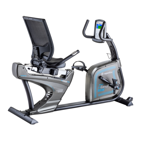
- Page 1 USER MANUAL – EN IN 8725 Recumbent inSPORTline R600i...
-
Page 2: Table Of Contents
CONTENTS SAFETY INSTRUCTIONS ............................ 3 IMPORTANT NOTES ............................3 EXPLODED DRAWING ............................4 PARTS LIST ................................4 CHECK LIST ................................9 ASSEMBLY ................................. 10 SM2570 iConsole+ INSTRUCTION MANUAL ....................16 TERMS AND CONDITIONS OF WARRANTY, WARRANTY CLAIMS ............20... -
Page 3: Safety Instructions
SAFETY INSTRUCTIONS To ensure the best safety of the exerciser, regularly check it on damages and worn parts. If you pass on this exerciser to another person or if you allow another person to use it, make sure that that person is familiar with the content and instructions in these instructions. -
Page 4: Exploded Drawing
The general rule is that exercisers and training devices are no toys. Therefore, they must only be used by properly informed or instructed persons. Stop your work-out immediately in case of dizziness, nausea, chest pain or any other physical symptoms. - Page 5 Sliding beam Spring washer D15.4 XD8.2x2T Allen bolt M8*1.25*50L Allen bolt M8x1.25x20L Allen bolt M8x1.25x15L Nylon nut M8*1.25*8T Curved washer D22xD8.5x1.5T Left rear chain cover Flat washer D16*D8.5*1.2T Allen bolt M8x1.25x15L Right crank 16R/L Pedal set Nylon washer D6*D19*1.5T Crank axle C-clip D22.5*D18.5*1.2T Bolt M6x1.0x15L Nylon nut M6x1.0x6T...
- Page 6 Foam Flat washer D24xD16x1.5T spacer D19*D13.1*4T Upper handle pulse cable Lower handle pulse cable Handlebar Handle pulse cable Upper handle pulse cable Bushing Upper computer cable Lower computer cable Sensor cable Electric cable Belt wheel Handle pulse sensor Waved washer D27*D21*0.3T Flat washer D24*D16*1.5T Round magnet Computer SM-2570-31...
- Page 7 Bushing D29*D11.9*9T Axle Stopper Protective cover Nut M6*1*6T Foam Left chain cover Right chain cover Seat post Plastic cover Allen bolt M8*1.25*40L Round wheel Nylon nut M8*1.25*8T Screw ST4.2x1.4x15L Buffer D20*10L*M8*1.25 Bolt M5x0.8x12L Screw ST4.2x1.4x20L Water bottle holder Bolt M5*0.8*15L Adjustable wheel Bushing D22.2*D8.2*7T Anti-loosen nut 3/8"-26UNFx6.5T...
- Page 8 Screw ST4*1.4L*25L Screw 1/4"-20牙*40L Screw cover D28*17(M6) Chest belt...
-
Page 9: Check List
CHECK LIST 122 & D28*D17*M6 M8*1.25*20L M8*15L D16*D8.5 X D15.4*D8.2*2T M8*1.25*50L D22*D8.5 1/4"-20*40L... -
Page 10: Assembly
ASSEMBLY STEP 1 (x8) M8*20L D15.4*D8.2*2T D16*D8.5*1.2T 13 7 9 FIG.1 1) Assemble the front stabilizer (3) and rear stabilizer (2) onto the main frame (1) by using the spring washer (7), the allen bolt (9), and the flat washer (13). 2) Adjust the proper height by turning the wheel of rear foot cap (91). - Page 11 STEP 2 FIG.2 (x4) M8*1.25*50L D16*D8.5*1.2T D15.4*D8.2*2T 1) Suggest assembling this step by two persons. 2) First, lift up the cover for handlebar post (64) like fig. (a), then connect the Upper&Lower computer cable (52A & 52B) like fig.(b) 3) Insert the handlebar post (5) on the main frame and tighten it by using the spring washer (7), the allen bolt (8), and the flat washer (13).
- Page 12 STEP 3 (x4) M5*0.8*10L (x2) M5*0.8*15L FIG.3 1) Assemble the upper handlebar pulse cable (46) to the computer (60). 2) Assemble the computer (60) to the handlebar post (5) by using the bolt (111). 3) Assemble the left and right pedal (16L &16R) on the crank (105 & 15). 4) Assemble the water bottle holder (97) onto the handlebar post by screw (98).
- Page 13 STEP 4 FIG.4 (x2) M8*50L D22*D8.5*1.5T 1) Assemble the handlebar (48) to the main frame (1) by using the allen bolt (8), and the curved washer (11). 2) Connect the plug of the lower handle pulse cable (47) with the handle pulse cable (49).
- Page 14 STEP 5 (x4) D28*D17*M6 1/4"-20*40L (x4) M8*15L D16*D8.5*1.2T FIG.5 1) Assemble the seat (42) on the seat post by using the allen bolt (9a) and the flat washer (13). 2) Assemble the backrest (38) to the backrest support tube by using the screw (120) and the screw cover (121).
- Page 15 The backrest can be adjusted as per above drawing: The bike can be moved as per above drawing:...
-
Page 16: Sm2570 Iconsole+ Instruction Manual
SM2570 iConsole+ INSTRUCTION MANUAL SUPPORT DEVICES Support iOS devices: Support Android devices: iPod touch (5th generation) Android tablet OS 4.0 or above iPod touch (4th generation) Android tablet resolution 1280X800 pixels iPod touch (3rd generation) Android phone OS 2.2 or above iPhone 5S Android phone resolution: iPhone 5C... - Page 17 Range 0.0 ~ 99.9 CALORIES Burned calories during workout display. Range 0 ~ 999 PULSE Pulse bpm displayed during exercise. Pulse alarm when over preset target pulse. Rotation per minute Range 0 ~ 999 WATT Workout power consumption In Watt Program mode, computer will remain preset watt value (setting range 0~350) MANUAL Manual mode workout.
- Page 18 Press UP and Down to select workout Manual Beginner Advance Sporty Cardio Watt MANUAL MODE Press START in main menu may start workout in manual mode. 1) Press UP or DOWN to select workout program, choose Manual and press Mode to enter. 2) Press UP or DOWN to preset TIME, DISTANCE, CALORIES, PULSE and press MODE to confirm.
- Page 19 1) Press UP or DOWN to select workout program, choose Sporty mode and press Mode to enter. 2) Press UP or DOWN to preset TIME. 3) Press START/STOP key to start workout. Press UP or DOWN to adjust load level. 4) Press START/STOP key to pause workout.
-
Page 20: Terms And Conditions Of Warranty, Warranty Claims
NOTE: 1. Once console is connect to tablet via Bluetooth, the console will power off. 2. Please exit iConsole app and turn off the Bluetooth from iPad, then the console will power on again. TERMS AND CONDITIONS OF WARRANTY, WARRANTY CLAIMS General Conditions of Warranty and Definition of Terms All Warranty Conditions stated hereunder determine Warranty Coverage and Warranty Claim Procedure. - Page 21 +420 556 770 190, Mobile: +420 604 853 019, servis@insportline.cz Fax: +420 556 770 192, (Service +420 556 770 191) Web: www.insportline.cz, www.worker.cz, www.worker-moto.cz INSPORTLINE, s.r.o. Bratislavska 36, 911 05 Trencin, Slovakia CRN: 36311723, VAT ID: SK2020177082 Orders: +421(0)326 526 701, +421(0)917 649 192, objednavky@insportline.sk...
Need help?
Do you have a question about the R600i and is the answer not in the manual?
Questions and answers