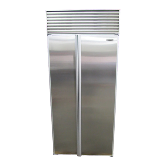
Sub-Zero 601R Installation Manual
600 series
Hide thumbs
Also See for 601R:
- Use & care manual (40 pages) ,
- Use & care information manual (40 pages) ,
- Use and care manual (32 pages)
Advertisement
Quick Links
Advertisement

Subscribe to Our Youtube Channel
Related Manuals for Sub-Zero 601R


Summary of Contents for Sub-Zero 601R
- Page 1 6 0 0 S E R I E S I N S T A L L A T I O N G U I D E ®...
-
Page 2: Installation
6 0 0 S E R I E S I N S T A L L A T I O N G U I D E ®... - Page 3 I N S T A L L A T I O N G U I D E Before you begin your installation of a Sub-Zero 600 Series Second, make sure that the actual equipment that was unit, there are a few things you should take special care to shipped to you matches the design you are expecting to observe.
-
Page 4: Specifications
M O D E L S 6 0 1 R , 6 0 1 R G A N D 6 0 1 F Step 1: First, make sure that the opening where the Sub-Zero is to be installed is properly prepared. Refer to the Pre-Installation Specifications illustrations and chart to be sure the space dimensions, electrical service and plumbing 24"... - Page 5 EXTENSION FRAME 11" (279) GRILLE LOCATE WATER SUPPLY 90˚ 90˚ WITHIN SHADED AREA 3" (76) 18" 6" (457) (152) FRONT VIEW Models 601R, 601RG, 601F, Models 561, 661, 642, 680, 685, 611, 611G, 650 and 650G 632, 690 and 695...
- Page 6 You will need a 115 volt, 60 Hertz electrical supply. Dedicate house supply. Use an easily accessible shut-off valve a separate 15 amp fuse or circuit breaker to the Sub-Zero between the supply and the refrigerator. This is usually unit, and follow any local codes that apply.
- Page 7 U N P A C K I N G T H E S U B - Z E R O For Models 601R, 601RG and 601F (stainless steel), the lower grille snaps out by pulling forward on the bottom of...
- Page 8 6 0 0 S E R I E S B L O C K I N G F O R S A F E T Y 3" SOFFIT WALL STUD (76) 1" (25) SCREW WARNING To prevent the unit from tipping forward and provide a stable installation, the unit must be secured in place WOOD BLOCK with an anti-tip device.
- Page 9 Protect any finished flooring before moving the unit in lower the cabinet. Refer to illustration 10. When the unit is place. All full-size Sub-Zero models are equipped with leveled properly, or squared off, door adjustments are less rollers, so you can easily move the unit into place. If for likely to be necessary.
- Page 10 Specifications charts, and be sure you are working with the the handles. Be sure the panel is inserted completely into Sub-Zero panel design called for in your installation plans. the channel for proper fit and alignment. See illustration 13. If your customer has chosen the stainless steel design, the...
- Page 11 Check the location of offset when you’re using specific rout- ing for the grip area only. Refer to the 600 Series section of the Sub-Zero Design Guide for a full-scale template of the standard full length handle and panel. Use this grid tem- plate to lay out your panel design for finger clearance when Illus.
- Page 12 1/4" (6) to a maximum of 1-1/8" (29). If the panel is thicker, you must rout out a minimum 1/4" (6) flat landing area to accommodate the bezel surrounding the glasswell. Models 601R and 601F Model 601RG 14"...
- Page 13 G L A S S W E L L – M O D E L S 6 8 5 A N D 6 9 5 Sub-Zero allows a 1/4" (6) space to slide the backing mate- The dispenser area of Models 685 and 695 has been engi- rial into place in the frame.
- Page 14 1/4" (6) flat landing NOTE: Dimensions in parentheses are in millimeters. area to accommodate the bezel surrounding the glasswell. NOTE: Panel specifications are for 600 Series overlay (O) models. Models 601R and 601F Model 601RG Models 611 and 650 Models 611G and 650G...
- Page 15 Refer to the Overlay Grille Panel Specifications chart and illustration 20 for exact sizing of all three panels. Additional panel design information can be found in the Sub-Zero Design Guide. O V E R L A Y G R I L L E P A N E L...
- Page 16 Drill three holes equidistant in a vertical section of the alu- 1/8" (3) THICK BATTENS minum frame, and install pan head screws. Do not drill SIDE OF SUB-ZERO UNIT through model and serial number plate. Anchor the side panel with decorative screws or finishing nails from a local FRAME 1/4"...
- Page 17 After installing front and side panels, leveling, doors adjusted. alignment and door adjustment, anchor the unit to the opening to assure a proper fit. The Sub-Zero Anchoring Kit • Drill three 3/16" (5) holes through both outer trims as (part # 4200900) is available from your Sub-Zero dealer. Be shown in illustration 24.
- Page 18 See illustration 28. Tighten firmly with a screwdriver. Optional 90˚ or 105˚ door stop kits for Models 601R, 601RG, 601F, 561, 661, 642, 680, 685, 632, 690 and 695 are available through your Sub-Zero dealer.
- Page 19 S E R V I C E F O R Y O U R S U B - Z E R O R E F R I G E R A T I O N S Y S T E M The importance of the installation of your Sub-Zero 600 Series unit cannot be overemphasized. The proper installa-...
- Page 20 ® S U B - Z E R O F R E E Z E R C O M P A N Y , I N C . 4717 Hammersley Road • Madison, Wisconsin 53711 (800) 222-7820 • (608) 271-2233 •...
Need help?
Do you have a question about the 601R and is the answer not in the manual?
Questions and answers