Epson EMP-TW1000 Service Manual
Hide thumbs
Also See for EMP-TW1000:
- User manual (76 pages) ,
- User manual (64 pages) ,
- User manual (9 pages)
Table of Contents
Troubleshooting

Related Manuals for Epson EMP-TW1000


Summary of Contents for Epson EMP-TW1000
- Page 1 Multi Media Projector Service Manual EMP-TW1000 www.electronicsrepair.net...
- Page 2 This Service Manual describes the hardware information necessary for troubleshooting and field service of the EMP-TW1000 HOME PROJECTOR. Before starting service on this unit, always check the EPSON website for additional up-to date service information provided in Technical Information Bulletins.
- Page 3 REASSEMBLY CHECK POINT Important tips for procedures are described under the heading C H E C K CHECK POINT P O I N T 2006 SEIKO EPSON CORPORATION SEIKO EPSON Revision:A...
- Page 4 EMP-TW1000 Manual Revision History History Date Detail of change First Release Rev.A 2006.11.02 Service memo Make a note here of important technical information from Technical Information bulletins. SEIKO EPSON Revision:A...
-
Page 5: Safety Instructions
EMP-TW1000 SAFETY INSTRUCTIONS 1. MAINTAINING OPERATOR SAFETY 1. PREVENTING ELECTRIC SHOCKS • Turn off the power switch and disconnect the power cord from the AC outlet before car- rying out any disassembly and assembly work on this projector. • If power needs to be supplied to the projector while the cover is removed (such as when... - Page 6 • When replacing the structural components inside the projector (including the lamp assy), use only replacement parts supplied by EPSON and listed in the projector's Parts List. • Use the accessory power cord and interface cable provided with the projector.
- Page 7 EMP-TW1000 Testing procedure Carry out testing in the order given below. Repair Insulation resistance test Ground continuity check Illumination check Safety inspections Testing methods 1). Insulation resistance test • Testing apparatus: Insulation ohmmeter (Rating: 500 V/100 MΩ) Check Item Tool...
- Page 8 EMP-TW1000 2). Ground continuity check • Testing apparatus: Multimeter (with sensitivity down to 0.1 Ω) Check Item Tool Standard Should be no resistance Ground continuity check Multimeter (0.5 Ω or less) • Multimeter settings Display 1. Turn on the power switch.
- Page 9 EMP-TW1000 Other • Check that the connectors at both ends of the power cord are not dirty or bent, and clean them if they are dirty. Furthermore, if there is any noticeable discoloration on the power cord, it should be replaced.
- Page 10 • Any questions regarding repairs and service to this projector (such as supply of parts and the contents of this Service Manual) should be directed to EPSON at the address below. Furthermore, information regarding matters such as technical changes to the projector are released when necessary in the form of Technical Information bulletins, and these should be referred to also.
-
Page 11: Table Of Contents
EMP-TW1000 Chapter 1 Product Specifications 1.1 Product Features ..................1-2 1.1.1 Feature of the projector ..............1-2 1.2 Components, Connectors and Switches ..........1-3 1.2.1 External Components..............1-3 1.2.2 Internal Components ..............1-5 1.2.3 Remote Control ................1-6 1.3 Specifications................... 1-7 1.4 Interface Specifications................ - Page 12 Tools and Equipment ..............4-4 4.1.3 Projector-Specific Service Precautions ......... 4-4 4.2 Projector Disassembly and Assembly............4-6 4.2.1 Removing the EMP-TW1000 Model Name Plate and EPSON 32H Logo Plate ............4-9 4.2.2 Removing the Air Filter Lid and Air Filter........4-10 4.2.3 Removing the Lamp Unit Lid and Lamp Unit.......
- Page 13 EMP-TW1000 Chapter 5 Appendix 5.1 AS (After Service) Menu ................5-2 5.1.1 How To Display the AS (After Service) Menu ....... 5-2 5.1.2 Initializing (Resetting) the AS Menu Values ........5-4 5.1.3 Software DIP Switches..............5-5 SEIKO EPSON 0-13 Revision:C...
-
Page 14: Chapter 1 Product Specifications
Chapter 1 Product Specifications... -
Page 15: Product Features
EMP-TW1000 1.1 Product Features The EMP-TW1000 is a full Hi-vision projector developed to target the home theater market that requires color reality and wide screens. With a lightweight and compact body, EMP- TW1000 offers high-quality color images in full colors sent from various compatible devices such as a VCR, video disc player, video camera, and personal computer. -
Page 16: Components, Connectors And Switches
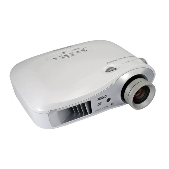
EMP-TW1000 1.2 Components, Connectors and Switches 1.2.1 External Components Horizontal Lens Adjustment Dial Control Panel Vertical Lens Adjustment Dial Air Exhaust Vent Zoom ring Remote Control Light-receiving Area Focus ring Figure 1-1. Main Unit Front Suspension Bracket Fixing Points (4 Points) - Page 17 EMP-TW1000 D Port Component Port PC Port HDMI Port Trigger Out Port Video Port S-video Port Rs-232c Port Figure 1-3. Input and Output Connectors (Operation) indicator Flashes or lights in different colors to indicate the operating sta- tus of the projector.
-
Page 18: Internal Components
EMP-TW1000 1.2.2 Internal Components Upper Case Unit Control Panel MA Board Assembly IF Board Optical Engine PS Ballast Unit Intake Fan Exhaust Fan Front Case Figure 1-5. Major Internal Components SEIKO EPSON Revision:A... -
Page 19: Remote Control
EMP-TW1000 1.2.3 Remote Control Remote control light-emitting area On/Off buttons Outputs remote control signals. Turns the projector power on/off. Indicator Illuminates when remote control signals are being output. Color Mode button Selects the color mode. Memory button Retrieves stored memories. -
Page 20: Specifications
EMP-TW1000 1.3 Specifications Projection System RGB Liquid Crystal Shutter Projection System Projection Method Front / Rear / Ceiling Mount Size 0.74 inches wide with MLA Driving Method Poly-silicon TFT Active Matrix Pixel number 2073600 dots (1920 x 1080) x 3... - Page 21 Brightness / Contrast / Tint / Saturation/ Input signal etc. Tilt Angle 0 to 2.1 degrees Controlled automatically with color mode Epson Cinema Filter (ON : Theater / Theater black 1 / Theater black 2 / Natural, OFF : Living room / Dynamic) Auto Iris...
- Page 22 EMP-TW1000 Lamp on 245W (Lamp high), 200W at (Lamp low) 100V area (JAPAN etc.) Standby mode Lamp on 245W (Lamp high), 200W at (Lamp low) Power 120V area Consumption (USA etc.) Standby mode Lamp on 240W (Lamp high), 200W at (Lamp low) 200-240V area (Europe etc.)
-
Page 23: Interface Specifications
EMP-TW1000 1.4 Interface Specifications Figure 1-7. 1.4.1 D terminal SENTORO half 14Pin CN102 Pin No. Pin Name Pin No. Pin Name YKF45-3001N (Not in use) (Not in use) (Not in use) D_ID3 (Not in use) (Not in use) D_DETX 1.4.2 Component terminal... -
Page 24: Hdmi
EMP-TW1000 1.4.3 PC Mini D-sub, 15pin CN100 Pin No. Signal Name Pin No. Signal Name 7513S-15G2-08 (Not in use) H Sync V Sync 1.4.4 HDMI 19 pin CN300 Pin No. Pin Name Pin No. Pin Name DC1R019NBA Rx2+ RxC- Rx2-... -
Page 25: S-Video Interface
EMP-TW1000 1.4.6 S-Video Interface 4-pin mini-DIN with detect pin CN3001 Pin No. Signal Name TCS7708-012021 Y signal input C signal input 1.4.7 Trigger out 3.5 Mini jack J3001 Pin No. Signal Name HTJ-035-18ABT +12V (Not in use) (Not in use) 1.4.8 RS-232C... -
Page 26: External Views
EMP-TW1000 1.5 External Views 59.1 97.3 170.6 406.1 121.3 92.8 62.8 4-M4x9 101.4 159.8 Unit: mm 52.8 Figure 1-8. External Dimensions SEIKO EPSON 1-13 Revision:A... - Page 27 EMP-TW1000 2.33 3.83 6.72 1.89 15.99 6.34 4.77 3.65 10.24 2.47 4-M4x9 3.15 2.91 3.99 6.29 Unit: Inch 11.81 2.08 Figure 1-9. External Dimensions SEIKO EPSON 1-14 Revision:A...
-
Page 28: Chapter 2 Theory Of Operation
Chapter 2 Theory of Operation... -
Page 29: Hardware Overview
EMP-TW1000 2.1 Hardware Overview The hardware for the EMP-TW1000 can basically be divided into two sections: the optical engine and the circuit system. This section of the manual describes functions of the major hardware components. The components and unit in the dotted frame shown in the diagram below make up an optical engine and MA Board Kit, which is provided as one part. -
Page 30: Circuit Component Connection Diagram
EMP-TW1000 2.1.1 Circuit Component Connection Diagram The circuit system is shown in the following diagram. The various components are connected to the MA board which is the central component of the system. Figure 2-2. MA Board Connectors SEIKO EPSON Revision:A... -
Page 31: Control Circuitry
EMP-TW1000 2.1.2 Control Circuitry The control circuits are illustrated in the following block diagram. Figure 2-3. Control Circuit Block Diagram SEIKO EPSON Revision:A... -
Page 32: Optical Engine
2).Low power consumption Power consumption of the panel driving system is highly reduced. (Only about 10 % of power consumption compared with a conventional EPSON 1080P panel.) Features of “Crystal Clear Fine (C Fine)” • Adoption of inorganic LC alignment layer reduces unevenness of molecular orientation. - Page 33 EMP-TW1000 Optical system drive block Figure 2-5. Optical Engine Functional Diagram The Lamp Unit, Light Guide Unit, POP Unit, and Projection Lens together make C H E C K P O I N T up the Optical Engine. These components are assembled and adjusted together at the factory, and are not available as separate service parts.
-
Page 34: Lamp Unit
Figure 2-7. Lamp Unit Control Circuits • The EMP-TW1000 has a sleep mode function that will automatically turn off the lamp if no new signals are input for a continuous period (Default is 30 minutes, the time can be set by the minute). -
Page 35: Ma Board
EMP-TW1000 2.3 MA Board The MA board processes the core circuit controls for the projector, including interface control, operation panel control, temperature sensor circuit and fan control, ballast power supply control and the Infrared RC board interface. The MA board also contains an imaging processor (PW328), EEPROM, digitizers (ADC and video decoder), and SDRAM memory. -
Page 36: Overview Of Operation
EMP-TW1000 2.3.2 Overview of Operation Projector control Controls the IF board, RC boards, etc. Digitalization control of the picture signal Converts the analog RGB image signals input from Computer and BNC from analog to digital form. Definition transformation control by the digital filter of the input picture signal Converts the resolution of the image signals input from Video and S-Video with the digital filter. -
Page 37: Interface Connectors
EMP-TW1000 2.4 Interface Connectors The MA board / IF board includes interface connectors for external devices such as video equipment and external control. The MA board / IF board is equipped with the following connectors. D Port Component Port PC Port... -
Page 38: Power Supply Unit
EMP-TW1000 2.5 Power Supply Unit The Power Supply Unit contains the power supply filter and the AC cord socket. Power Supply Unit Cable AC Figure 2-12. Power Supply Unit 2.5.1 Power Supply Circuit Block Diagram AC Input EMI Filter EMI Filter... -
Page 39: Overview Of Operation
EMP-TW1000 2.5.2 Overview of Operation The output cable of the power supply unit is connected to CN4000 on the MA board. It allows the following voltages and signals to be transmitted. • DC output • The power supply On/Off signal (PWON) -
Page 40: Connector Cn4000 Pin Layout
EMP-TW1000 2.5.3 Connector CN4000 Pin Layout Figure 2-14. Power Supply Connector (connected to CN4000 on the MA board) Pinout Definition Pin No. Signal name PFCON +5 V_T +5 V_T +5 V_T +13 V +18 V (Not in use) SEIKO EPSON... -
Page 41: Ballast Unit
EMP-TW1000 2.6 Ballast Unit The Ballast Unit re-regulates a DC voltage (340-400VDC) supplied from the Power Supply Unit, and generates 170W for the UHE lamp. Power Supply Unit Ballast Unit Cable AC Figure 2-15. Ballast Unit 2.6.1 Power Supply Circuit Block Diagram... -
Page 42: Rc Receiver Sensor
EMP-TW1000 2.7 RC Receiver Sensor The Remote Control (RC) board is equipped with sensors that detect (receive) infrared signals transmitted from the remote control. The two RC IR sensors are mounted on the front and rear of the projector. Front IR Receiver Sensor Rear Front IR Receiver Sensor Figure 2-17. -
Page 43: Temperature Control
EMP-TW1000 2.8 Temperature Control 2.8.1 Sensors and Switches This projector is equipped with the devices shown in the table below in order to protect the safety of the operator and maintain general safety with regard to the projector itself by preventing abnormalities in operation. - Page 44 EMP-TW1000 TH Board The TH Board is attached to the Exhaust Duct to detect the temperature of the lamp section. To prevent damage to the surrounding components from overheating, the power save controller on the MA board first provides a warning indication through the temperature indicator LED, and stops the output of the ballast when the temperature rises above a given level.
- Page 45 EMP-TW1000 LV Thermistor This is a backup overheating prevention sensor mounted on the upper surface of the Optical Engine (Prism Unit). To prevent damage to the surrounding components from overheating, the power save controller on the MA board first provides a warning indication through the warning indicator LED, and stops the output of the ballast when the temperature rises above a given level.
-
Page 46: Fan Operation
EMP-TW1000 2.8.2 Fan Operation There are four cooling fans inside the projector. These fans discharge heated air produced mainly by the Lamp Unit, Power Supply Unit. Exhaust Fan Power Supply Fan LV Fan Lamp Fan Figure 2-23. Fan Locations SEIKO EPSON... - Page 47 EMP-TW1000 IC550 IC1103 Figure 2-24. Fan Control Circuit Block SEIKO EPSON 2-20 Revision:A...
-
Page 48: Operation Control
EMP-TW1000 Operation Control The MA board is connected to two thermistors monitoring the internal temperature. The thermal monitor CPU (IC1103) controls the operation of the three fans* (LV fan, Exhaust fan and Power Supply fan), based on the temperatures detected by the thermistors. (*: Lamp fan runs at a constant speed.) -
Page 49: Led Indicators
EMP-TW1000 2.9 LED Indicators The MA board has two LEDs that indicate the operating status of the projector. (operation) indicator (warning) indicator Figure 2-25. Status Indicator LEDs Location The following tables show what the indicators mean and how to remedy problems the they indicate. - Page 50 EMP-TW1000 When the (operation) indicator is lit or flashing normal When the (warning) indicator is off : Lit : Flashing Standby condition Orange If you press , projection will start after a brief interval. Warm-up in progress Green Warm-up time is approximately 30 seconds.
-
Page 51: Chapter 3 Troubleshooting
Chapter 3 Troubleshooting... -
Page 52: Before Carrying Out Troubleshooting
EMP-TW1000 3.1 Before Carrying Out Troubleshooting • If repairs involving the replacement of parts or components have been carried out, always be sure to re-check whether the replacement parts themselves are operating correctly or not in order to determine whether the problem is the result of something such as a loose connec- tor. -
Page 53: Overview
EMP-TW1000 3.2 Overview Check the nature of the problem using the following flow diagram, and then proceed to the corresponding flow chart (on the following pages). START • Check for any external abnormalities, such as a damaged case. Exterior Check •... -
Page 54: Exterior Check
EMP-TW1000 3.2.1 Exterior Check START • There should be no damage, deformation or cracking due to external forces. Upper Case Unit • The lower case should be installed correctly. • The remote signal receiver should be clean and free from foreign materials. -
Page 55: Internal Cable Check
EMP-TW1000 3.2.2 Internal Cable Check Turn off the power and disconnect the power cable before you begin the following connector checks. See Figure 2-2 on page 2-3 for the location of the MA Board connectors. START Upper Case Unit Removal •... -
Page 56: Power Supply On/Off
EMP-TW1000 3.2.3 Power Supply On/Off START Connect the power cord. Turn on the main power switch. Reconnect or replace Is the indicator lit the control panel. orange? Press the [Power] button of Press the [Power] button on the control panel. Does the the remote control. - Page 57 EMP-TW1000 (Continued from previous page) Is the lamp turned on? Replace the Optical Engine. To START Press the [Power] button to turn off the power. Does the indicator flash Replace the Optical Engine. orange? To START Does the indicator light Replace the Optical Engine.
-
Page 58: Image Display And Quality
EMP-TW1000 3.2.4 Image Display and Quality The image quality can also be affected by condensation or by a dirty lens. C A U T I O N If condensation forms, the problem will correct itself naturally if the projector is left to stand for a while. - Page 59 EMP-TW1000 (Continued from previous page) Connect the host computer to the PC connector and display an image. Is the image quality good? Connect external devices to all the interfaces. 1.Press the [Menu] Does an image appear button. on the screen? 2.Select the "Picture"...
-
Page 60: Control Panel
EMP-TW1000 3.2.5 Control Panel START Turn on the main Power Switch. Does pressing the [Power] button turn the power ON/OFF? Does pressing the [Menu] button switch the image to the menu window? Does pressing the [Source] button change the input video sources? -
Page 61: Remote Control Operation
EMP-TW1000 3.2.6 Remote control operation START Turn on the main power switch. Does the remote control Can the power be turned Can the power be turned work 10m away from the on and off using the on and off using the... -
Page 62: Other
EMP-TW1000 3.2.7 Other START • Check for any objects around the Exhaust Fan, LV Fan, Lamp Fan and Power Is the projector making abnor- mal noise? Supply Fan. • The cause might be a malfunction of the power supply unit (pulse transformer vibration, etc.). -
Page 63: Chapter 4 Disassembly/Assembly
Chapter 4 Disassembly/Assembly... -
Page 64: Overview
4.1 Overview This chapter describes the procedures for disassembling and assembling the main components of the EMP-TW1000 projector. Unless otherwise specified, reassembly is the reverse of the disassembly procedure. Read the precautions described in the next section before starting. 4.1.1 Precautions Some procedures require specific precautions that must be followed, and those will be noted throughout this chapter. - Page 65 Use static discharge equipment such as anti-static wrist straps when accessing internal components to protect sensitive electronic components and circuitry. Do not use second source ICs or other components not approved by Epson. They could cause damage to the Epson product or could void the Epson warranty.
-
Page 66: Tools And Equipment
EMP-TW1000 4.1.2 Tools and Equipment The tools and equipment in the following table will be needed. All are commercially available, and should be made ready beforehand. Table 4-1. Tools Needed Name Application Phillips screwdriver No. 0 Disassembling the Focus ring Disassembling the outer case and inner Phillips screwdriver No. - Page 67 EMP-TW1000 Points to Note When Working Detailed points to note are given in each section, so be sure to read each section thoroughly before beginning the disassembly procedure. Below are several general points which should be noted. • When the projector is disassembled, the dust in and around parts such as the fans and air filter may get transferred to other parts such as the R, G and B light valves which are the central part of the display mechanism.
-
Page 68: Projector Disassembly And Assembly
EMP-TW1000 4.2 Projector Disassembly and Assembly The general disassembly procedure for the EMP-TW1000 projectors is illustrated below. Except where indicated separately, all reassembly should be carried out by following the disassembly procedures in reverse. Detailed disassembly procedures for each component are given in Sections 4.1.2 to 4.2.19, which links to the flowchart given below. - Page 69 EMP-TW1000 The table below shows the part names used in this chapter and their official names given in the After Service Part List in the SPI (Service Part Information). Official Name used in SPI Names used this Chapter Optical Engine and MAB set...
- Page 70 Upper Case; B PRINTED CIRCUIT BOARD ASSEMBLY; SW_R2 SW Board Assy. BUTTON, SW SW Button cable sw; Au Cable SW; Au MODEL NAME PLATE, EMP-TW1000 EMP-TW1000 Model Name Plate FOCUS RING; B Focus Ring; B ZOOM RING; B Zoom Ring; B...
-
Page 71: Removing The Emp-Tw1000 Model Name Plate And Epson 32H Logo Plate
4.2.1 Removing the EMP-TW1000 Model Name Plate and EPSON 32H Logo Plate 1. Using a screwdriver or a similar tool, push the EMP-TW1000 Model Name Plate from its backside through the hole of the Upper Case; B, and remove the plate. (When removing the Upper Case;... -
Page 72: Removing The Air Filter Lid And Air Filter
EMP-TW1000 4.2.2 Removing the Air Filter Lid and Air Filter 1. Press the tab of the Air Filter Lid in the direction of the arrow, and remove the Air Filter Lid. 2. Remove the Air Filter from the main unit. -
Page 73: Removing The Lamp Unit Lid And Lamp Unit
EMP-TW1000 4.2.3 Removing the Lamp Unit Lid and Lamp Unit 1. Press the tabs of the Lamp Unit Lid in the direction of the arrow, and remove the Lamp Unit Lid. 2. Loosen the two screws that secure the Lamp Unit, and remove the Lamp Unit. -
Page 74: Removing The Foot; A10, Foot Holder; A, And Foot Rubber
EMP-TW1000 4.2.4 Removing the Foot; A10, Foot Holder; A, and Foot Rubber 1. Pull out the foot as far as it will go, insert a flat-blade screwdriver into the grooves on both sides of the Foot; A10, and remove the Foot Holder; A and the Foot; A10 while pressing the tabs in the direction of the arrow. -
Page 75: Removing The Upper Case; B
EMP-TW1000 4.2.5 Removing the Upper Case; B 1. Remove the eight screws (C.B.P-TITE SCREW, 4x10, F/ZN-3C) that secure the Upper Case; B. Figure 4-6. 2. Remove the two screws (C.B.SCREW, 3x8, F/NI) that secure the IF Case to the Upper Case;... - Page 76 EMP-TW1000 4. Release the lock of the connector (CN1205) on the MA board, and take out the Cable SW;Au. Figure 4-8. SEIKO EPSON 4-14 Revision:A...
-
Page 77: Removing The Sw Board Assy., Cable Sw;Au, And Sw Button
EMP-TW1000 4.2.6 Removing the SW Board Assy., Cable SW;Au, and SW Button 1. Remove the four screws (C.C.P-TITE SCREW 3x8, F/ZN-3C) that secure the SW Board Assy., and remove the screw (C.C.P-TITE SCREW 3x8, F/ZN-3C) that secures the SW Button. - Page 78 EMP-TW1000 Fold the EMI suppressor;B along the dotted line and attach it on the Cable C A U T I O N SW;Au while wrapping the Cable SW;Au as shown in Figure 4-10. EMI suppressor;B Cable SW;Au EMI suppressor;B Figure 4-10.
-
Page 79: Removing The Focus Ring; B, Zoom Ring; B, Zoom Ring Shade, Zoom Ring Cushion, Front Case Unit; F, Rc Board Assy., Rcr Cable; Fif, Rc Filter, And Exhaust Duct Cushion
EMP-TW1000 4.2.7 Removing the Focus Ring; B, Zoom Ring; B, Zoom Ring Shade, Zoom Ring Cushion, Front Case Unit; F, RC Board Assy., RCR Cable; FIF, RC Filter, and Exhaust Duct Cushion 1. Remove the three screws (C.P.B-TITE SCREW, 1.7x4, F/NI) that secure the Focus Ring; B, and remove the Focus Ring;... - Page 80 EMP-TW1000 7. Remove the screw (C.C.P-TITE SCREW, 3x6, F/ZN-3C) that secures the RC Board Assy., and remove the RC Board Assy. 8. Remove the RCR Cable; FIF from the RC Board Assy. 9. Remove the RC Filter from the Front Case Unit; F.
-
Page 81: Removing The Ma Ground Plate And Ma-If Board Assy
EMP-TW1000 4.2.8 Removing the MA Ground Plate and MA-IF Board Assy. 1. Release the locks of the R, G, and B light valve cable connectors, and disconnect the R, G, and B light valve cables. Light Valve R Locked Light Valve G... - Page 82 EMP-TW1000 2. Disconnect all the cable connectors that are connected to the MA board. CN4000 CN1504 CN1700 CN1303 CN1701 CN1301 CN1503 CN1300 CN1501 CN1505 CN1500 CN1304 CN1703 CN1305 CN1702 CN1302 Figure 4-15. SEIKO EPSON 4-20 Revision:A...
- Page 83 EMP-TW1000 When installing the MA-IF Board Assy., pay attention to the following C A U T I O N instructions. 1). Twist the TH Board Assy. Cable and Exhaust Fan; B Cable around the Power Cable, then secure the cables by putting them into the space by the Exhaust Duct as shown in Figure 4-16.
- Page 84 EMP-TW1000 3. Remove the five screws (C.C.SCREW, 3x6, F/ZN-3C) that secure the MA Ground Plate, and remove the MA Ground Plate. Plate, Ground, MA Figure 4-18. SEIKO EPSON 4-22 Revision:A...
- Page 85 EMP-TW1000 4. Remove the screw (C.C.SCREW, 3x6, F/ZN-3C) that secure the IF Panel and the screw that secures the IF Ground Plate, and remove the two screws (C.B.SCREW, 3x8, F/NI) that secure the IF Case to the Lower Case. 5. Remove the two screws (C.C.SCREW, 3x6, F/ZN-3C) that secure the MA-IF Board Assy., and remove the MA-IF Board Assy.
-
Page 86: Removing The If Case, If Label; A, If Shade Sheet, And If Shade Cushion
EMP-TW1000 4.2.9 Removing the IF Case, IF Label; A, IF Shade Sheet, and IF Shade Cushion 1. Remove the two screws (C.B.SCREW, 3x8, F/ZI) that secure the IF Case, and remove the IF Case from the MA-IF Board Assy. 2. Remove the IF Label; A from the IF Case. -
Page 87: Removing The If Panel, Rc Board Assy., Rcr Cable; Fif, If Board Assy
EMP-TW1000 4.2.10 Removing the IF Panel, RC Board Assy., RCR Cable; FIF, IF Board Assy. 1. Remove the one screw (C.C.SCREW, 3x6, F/Z-3C) that secures the RC Board Assy. 2. Remove the two screws (C.P.B-TITE-A.SCREW, 3x8, F/NI) that secure the D-terminal connector, and remove the four screws (Screw, HSH 4-40) that secure the D-SUB connector. - Page 88 EMP-TW1000 6. Remove the IF Board Assy. from the MA Board Assy. MA Board Assy. Printed Circuit Board Assembly; IF_R1 Figure 4-23. SEIKO EPSON 4-26 Revision:A...
- Page 89 EMP-TW1000 Attach EMI Suppressors on top of the MA board following the instructions C A U T I O N below. 1). Attach the EMI Suppressor on the ICs (1) while matching the centers as shown in Figure 4-24. 2). Attach two EMI Suppressor; C on top of each other on the IC (2) while matching the centers as shown in Figure 4-24.
- Page 90 EMP-TW1000 Attach EMI Suppressors and heat-resistant tape on the bottom of the MA C A U T I O N board following the instructions below. 1). Attach the EMI Suppressor; D on the area (1) while aligning it along the standard line (A) as shown in Figure 4-25.
-
Page 91: Removing The Ps Ballast Assy
EMP-TW1000 4.2.11 Removing the PS Ballast Assy. 1. Remove the screw (C.C.P-TITE SCREW 3x8, F/ZN-3C) that secures the Safety Switch, and remove the Safety Switch. 2. Remove the two screws (C.C.P-TITE SCREW 3x8, F/ZN-3C) that secures the Ballast Connector, and remove the Ballast Connector. -
Page 92: Removing The Lamp Plate, Ps Shade Plate, Ma Fasten Plate Left, Ma Fasten Plate Right, Shielding Gasket, Ma Fasten Support Plate, Lamp Insulation Sheet And Optical Engine
EMP-TW1000 4.2.12 Removing the Lamp Plate, PS Shade Plate, MA Fasten Plate Left, MA Fasten Plate Right, Shielding Gasket, MA Fasten Support Plate, Lamp Insulation Sheet and Optical Engine 1. Remove the seven screws (C.B.P-TITE SCREW, 3x10, F/ZB-3C) that secure the Lamp Plate and remove the Lamp Plate. - Page 93 EMP-TW1000 The Optical Engine can be divided into two parts A and B. Be careful not to C A U T I O N drop the Optical Engine when removing it. 7. Remove the fore screws (C.B.P-TITE SCREW, 3x10, F/ZB-3C) that secure the Optical Engine, and remove the Optical Engine.
- Page 94 EMP-TW1000 Secure the CF Motor Cable and Auto Iris Sensor Cable with heat-resistant tape C A U T I O N as shown in Figure 4-30. Auto Iris Sensor Cable CF Motor Cable heat-resistant tape Figure 4-30. SEIKO EPSON 4-32...
- Page 95 EMP-TW1000 Handle with care! The FPCs of EMP-TW1000 are very thin and fragile. Do not C A U T I O N bend the FPCs forcibly. Since the ICs are mounted on the FPCs, strong bending may cause the ICs to peel off or breaking of the FPCs.
-
Page 96: Removing The Motor Cf Assy., Cf Sw Assy., Micro Sw Assy., Top Ml Fasten Spring, Frame Cf Assy., And Auto Iris Assy
EMP-TW1000 4.2.13 Removing the Motor CF Assy., CF SW Assy., Micro SW Assy., Top ML Fasten Spring, Frame CF Assy., and Auto Iris Assy. 1. Remove the two screws (C.B.P-TITE SCREW, 3x10, F/ZB-3C) that secure the Motor CF Assy., and remove the Motor CF Assy. from the Optical Engine. - Page 97 EMP-TW1000 Install the Auto Iris Assy. with the shutters closed. C A U T I O N Figure 4-34. When installing the Frame CF Assy., align the left edge of the Frame CF Assy. with the mark-off line marked on the CF SW Assy.
-
Page 98: Removing The Exhaust Fan; B, Exhaust Duct, Inshulock T-18S, Th Board Assy., C Cable; 170, Ma Fasten Plate; Ps, And Fasten Plate; A
EMP-TW1000 4.2.14 Removing the Exhaust Fan; B, Exhaust Duct, Inshulock T-18S, TH Board Assy., C Cable; 170, MA Fasten Plate; PS, and Fasten Plate; A 1. Remove the three screws (C.B.P-TITE SCREW, 3x10, F/ZB-3C) that secure the Exhaust Fan Assy., and remove the Exhaust Fan Assy. - Page 99 EMP-TW1000 When installing the Inshulock T-18S, pay attention to the following C A U T I O N instructions. 1). Route the Exhaust Fan Cable and TH Board Assy. Cable as shown in Figure 4-32. Make sure not to let the parts of the cables shown in the dotted circle slacken.
-
Page 100: Removing The Light Valve Duct, Pbs Duct Sheet, Light Valve Intake Duct, Light Valve Sheet, Intake Fan, And Light Valve Cushion
EMP-TW1000 4.2.15 Removing the Light Valve Duct, PBS Duct Sheet, Light Valve Intake Duct, Light Valve Sheet, Intake Fan, and Light Valve Cushion 1. Remove the two screws (C.B.P-TITE SCREW, 3x10, F/ZB-3C) that secure the Light Valve Duct, and remove the Light Valve Duct. -
Page 101: Removing The Lmp Intake Duct, Lamp Fan, And Lamp Fan Guard
EMP-TW1000 4.2.16 Removing the LMP Intake Duct, Lamp Fan, and Lamp Fan Guard 1. Remove the two screws (C.B.P-TITE SCREW, 3x10, F/ZB-3C) that secure the LMP Intake Duct, and remove the LMP Intake Duct. 2. Remove the two screws (C.B.P-TITE SCREW, 3x25, F/ZN-3C) that secure the Lamp Fan, and remove the Lamp Fan from the LMP Intake Duct. -
Page 102: Removing The Ac Cable, And Lensbase Ground Plate; A
EMP-TW1000 4.2.17 Removing the AC Cable, and Lensbase Ground Plate; A 1. Remove the screw (C.B.P-TITE SCREW, 3x10, F/ZB-3C) that secures the AC Cable, and remove the AC Cable. 2. Remove the Lensbase Ground Plate; A from the AC Cable. -
Page 103: Removing The Ps Duct, Ps Intake Duct, Intake Fan, Intake Fan Frame, Ballast Duct Sheet, Ps Duct Sheet, And Light Valve Cushion
EMP-TW1000 4.2.18 Removing the PS Duct, PS Intake Duct, Intake Fan, Intake Fan Frame, Ballast Duct Sheet, PS Duct Sheet, and Light Valve Cushion 1. Remove the two screws (C.B.P-TITE SCREW, 3x10, F/ZB-3C) that secure the PS Duct, and remove the PS Duct. -
Page 104: Removing The Lamp Lid Detection Switch, Lamp Lid Detection Switch Plate, Plate Ps Conduction A, Plate Ps Conduction B, Rc Filter, Heatresistant Sheet; A, Heatresistant Sheet; B, And Lower Case
EMP-TW1000 4.2.19 Removing the Lamp Lid Detection Switch, Lamp Lid Detection Switch Plate, Plate PS Conduction A, Plate PS Conduction B, RC Filter, Heatresistant Sheet; A, Heatresistant Sheet; B, and Lower Case 1. Remove the screw (C.B.P-TITE SCREW, 3x10, F/ZB-3C) that secures the Lamp Lid Detection Switch Plate, and remove the Lamp Lid Detection Switch Plate. - Page 105 EMP-TW1000 Affix the Heatresistant Sheet; A and Heatresistant Sheet; B as shown in Figure C A U T I O N 4-47. Affix the Heatresistant Sheet; B, overlapping approximately 1mm onto the Heatresistant Sheet; A. Heatresistant Sheet; A Heatresistant Sheet; B Figure 4-47.
-
Page 106: Chapter 5 Appendix
Chapter 5 Appendix... -
Page 107: As (After Service) Menu
EMP-TW1000 The contents of this chapter are for use only by Epson Authorized Servicers, and C A U T I O N are not to be disclosed to others without the express written consent of Epson. 5.1 AS (After Service) Menu The AS (After Service) menu provides information and settings that are not displayed on the standard menu. - Page 108 EMP-TW1000 When the video source is S-Video or Video, the following screen (Page 1) is displayed. XXXXXXXXXXXXXX XXXXXXXXXXXXXX Video Signal Video Signal : ----------- : ----------- Total Operation Time Total Operation Time : 0H : 0H Lamp Op. Time (C) Lamp Op.
-
Page 109: Initializing (Resetting) The As Menu Values
EMP-TW1000 Item Contents Representation Internal overheat Fan error Thermistor error Lamp burnt out Lighting failure Internal error (RAM) Internal error (ROM) 2-digit number (00-99) Error Count Internal error (I2S) Over 99: “99” (times) Internal error (DR) (Not cleared to “0.”) -
Page 110: Software Dip Switches
EMP-TW1000 Clearing the Lamp Clearing the AS Clearing the Log Type Information Information Information Spacing Error Log No Change No Change (Status of acquiring none) Error Count No Change No Change Reset to 0 Control No Change No Change No change 5.1.3 Software DIP Switches... - Page 111 EMP-TW1000 DIP-SW Default Function Setting Value Note Setting reserved Setup level 0: 0 %, 1: 7.5 % Varies by destination 0: disabled Lamp noise analysis mode 1: enabled reserved reserved reserved reserved reserved 0: disabled (no display) Dot defect detection...
Need help?
Do you have a question about the EMP-TW1000 and is the answer not in the manual?
Questions and answers