Table of Contents
Advertisement
Quick Links
See also:
User Manual
User Manual
Installation
IP65/67 Switch
OCTOPUS 8M..., OCTOPUS 16M..., OCTOPUS 24M...,
OCTOPUS OS32...
OCTOPUS 8M
U : 24 - 48 V
in
CLASS 2 I : 0,5 - 0,1 A
in
OCTOPUS 8M
OCTOPUS 8M
U : 24 - 48 V
CLASS 2 I : 1,4 - 0,25 A
in
in
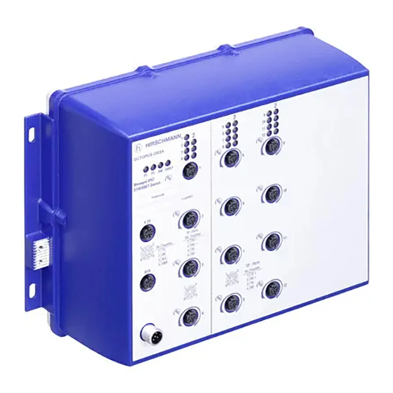
OCTOPUS 24M
x y
OCTOPUS
OS32
Managed
P
ETHERNET Switch
P1 P2 RM FAULT
Produktcode
IP-ADDRESS
V.24
1
2
4
3
Pin
Function
1
TX
2
RX
1
3
N.C.
ACA
4
GND
8
1
7
2
1
6
3
5
4
Pin
Function
1
MDX1+
2
2
MDX1 -
Power
3
MDX0+
5
4
MDX0 -
3
2
5
MDX2+
2
6
MDX2 -
7
MDX3 -
4
1
8
MDX3+
Pin
Function
1
+48V DC
1
2
3
0V
4
+48V DC
4
FAULT
5
OCTOPUS OS32-081602T6T6...
Installation OCTOPUS 8M/16M/24M/OS32
Release 11 01/2013
OCTOPUS 8M
U : 24 - 48 V
CLASS 2 I : 1,1 - 0,2 A
in
in
OCTOPUS 16M
3
7
11
15
4
8
12
16
5
9
13
17
6
10
14
18
3
7
11
15
4
8
12
16
5
9
13
17
6
10
14
18
TP-Ports
2
3
OCTOPUS 16M-Train-BP
Managed IP67
ETHERNET Switch
1
2
4
3
Pin
Function
1
TX
2
RX
3
N.C.
4
GND
5
3
2
4
1
Pin
Function
1
+24V DC
2
3
0V
4
+24V DC
FAULT
5
U : 24 - 48 V
in
OCTOPUS 16M-Train-BP
OCTOPUS 24M-Train-BP
Managed IP67
ETHERNET Switch
1
2
4
3
Pin
Function
1
TX
2
RX
3
N.C.
4
GND
5
3
2
1
2
4
1
4
3
Pin
Function
Pin
Function
1
+24V DC
Bypass Function:
1
TD +
2
2
RD +
Port 4
3
0V
3
TD −
4
+24V DC
4
RD −
FAULT
5
Power off
Port 8
U : 24 - 48 V
in
CLASS 2 I : 0,27 - 0,14 A
in
OCTOPUS 24M-Train-BP
x y
3
4
OCTOPUS
5
OS32
6
Managed
P
ETHERNET Switch
P1 P2 RM FAULT
1
Produktcode
V.24
IP-ADDRESS
1
2
4
3
Pin
Function
1
TX
2
RX
3
N.C.
ACA
4
GND
2
Power
5
3
2
4
1
Pin
Function
1
+48V DC
1
2
2
3
0V
4
+48V DC
4
3
FAULT
5
OCTOPUS OS32-081602O6O6...
https://hirschmann-support.belden.eu.com
1
2
4
3
Pin
Function
1
TD +
Bypass Function:
2
RD +
Port 4
3
TD −
4
RD −
Power off
Port 8
CLASS 2 I : 0,27 - 0,14 A
in
7
11
15
8
12
16
9
13
17
10
14
18
3
7
11
15
4
8
12
16
5
9
13
17
6
10
14
18
TP-Ports
Technical Support
Advertisement
Table of Contents

Subscribe to Our Youtube Channel
Related Manuals for Hirschmann OCTOPUS 8M Series


Summary of Contents for Hirschmann OCTOPUS 8M Series
-
Page 1: User Manual
MDX1 - Power Power MDX0+ MDX0 - MDX2+ MDX2 - MDX3 - MDX3+ TP-Ports TP-Ports Function Function +48V DC +48V DC +48V DC +48V DC FAULT FAULT OCTOPUS OS32-081602T6T6... OCTOPUS OS32-081602O6O6... Installation OCTOPUS 8M/16M/24M/OS32 Technical Support Release 11 01/2013 https://hirschmann-support.belden.eu.com... - Page 2 In addition, we refer to the conditions of use specified in the license contract. You can get the latest version of this manual on the Internet at the Hirschmann product site (www.hirschmann.com). Printed in Germany Hirschmann Automation and Control GmbH Stuttgarter Str.
-
Page 3: Table Of Contents
Contents Safety instructions About this Manual Legend Device description General device description Description of the device variants 1.2.1 Devices without Power over Ethernet 1.2.2 Devices with Power over Ethernet Power supply PoE supply voltage (optional) Interfaces 1.5.1 10/100 Mbit/s twisted pair connection (4-pin M12 connector, D-coded) 1.5.2 10/100 Mbit/s twisted pair connection for PoE (4-pin M12 sockets) - Page 4 Connecting the supply voltage, starting up Connecting the data lines Basic set-up Monitoring the ambient air temperature Maintenance and service Disassembling the SFP transceivers (optional) Technical data Further Support Installation OCTOPUS 8M/16M/24M/OS32 Release 11 01/2013...
-
Page 5: Safety Instructions
Safety instructions Certified usage Only use the device for application cases that are described in the Hirschmann product information, including this manual. Only operate the device according to the technical specifications. Operational environment: In the inside of vehicles ... -
Page 6: General Safety Instructions
Housing Only technicians authorized by the manufacturer are permitted to open the housing. The surfaces of the device housing may become hot. Avoid touching the device while it is operating. Wait until the device has cooled down. Environment Operate the device at the specified surrounding air temperature (temperature of the surrounding air at a distance of up to 1.97 in (5 cm) from the device) and relative air humidity specified in the technical data. - Page 7 Non-observance of these safety instructions can cause material damage and/or injuries. Only appropriately qualified personnel should work on this device or in its vicinity. The personnel must be thoroughly familiar with all the warnings and maintenance procedures outlined in this operating manual.
- Page 8 In accordance with the above-named EU directive(s), the EU conformity declaration will be at the disposal of the relevant authorities at the following address: Hirschmann Automation and Control GmbH Stuttgarter Str. 45-51 72654 Neckartenzlingen Germany Tel.: +49 (0)1805 14-1538 The device can be used in the industrial sector.
- Page 9 FCC note This device complies with part 15 of the FCC rules. Operation is subject to the following two conditions: (1) this device may not cause harmful interference; (2) this device must accept any interference received, including interference that may cause undesired operation. Appropriate testing has established that this device fulfills the requirements of a class A digital device in line with part 15 of the FCC regulations.
-
Page 10: About This Manual
About this Manual The “Installation” user manual contains a device description, safety instructions, a description of the display, and the other information that you need to install the device. The following manuals are available as PDF files on the CD/DVD supplied: ... -
Page 11: Device Description
You will find these manuals as PDF files on the enclosed CD/DVD, or you can download them from the Internet on the Hirschmann product pages (www.hirschmann.com). The Hirschmann network components help you ensure continuous communication across all levels of the company. Connect your devices to: ... -
Page 12: Description Of The Device Variants
the EAGLE security system products for the LION control room / MACH 100 family Description of the device variants 1.2.1 Devices without Power over Ethernet The following device variants provide 8 to 24 10BASE-T/100BASE-TX ports (RJ45 connections) for connecting network segments or terminal devices: ... -
Page 13: Devices With Power Over Ethernet
1.2.2 Devices with Power over Ethernet The following device variants, i.e. OCTOPUS ...PoE... and OS32..., support Power over ETHERNET (PoE) in accordance with IEEE 802.3af: OCTOPUS 8M-8PoE OCTOPUS 8M-6PoE OCTOPUS 16M-8PoE OCTOPUS 24M-8PoE OCTOPUS OS32-081602T6T6TPEPHH ... -
Page 14: Power Supply
The supply voltage and the signal contact are connected by means of a 5-pin M12 connector (A coding, e.g. ELWIKA 5012 PG7 from Hirschmann, included in the delivery). Redundant power supplies can be used. Both inputs are uncoupled. There is no distributed load. -
Page 15: Interfaces
Interfaces 1.5.1 10/100 Mbit/s twisted pair connection (4-pin M12 connector, D-coded) 10/100 Mbit/s TP ports enable the connection of terminal devices or independent network segments according to the IEEE 802.3 10BASE- T/100BASE-TX standard. These ports support: Autonegotiation Autopolarity ... -
Page 16: 10/100/1000 Mbit/S Twisted Pair Connection (8-Pin M12 Connector, X-Coded)
Figure Function PoE(PSE) Transmit Data + Receive Data + − TX− Transmit Data − RX− Receive Data − − Housing: shield Table 2: Pin assignment of the TP/TX interface for PoE for the voltage supply to the wire pairs transmitting the signal (M12 socket) 1.5.3 10/100/1000 Mbit/s twisted pair connection (8-pin M12 connector, X-coded) -
Page 17: 100/1000 Mbit/S Fo Connection (Sfp, Ip67-V1 Connector Based On Iec 61076-3- 106, Variant 1)
Patch cables Wire pairs M12 4-pin on M12 4-pin, crossed 1 (TX+) – 2 (RX+) (MDI to MDI) 2 (RX+) – 1 (TX+) 3 (TX−) – 4 (RX−) 4 (RX−) – 3 (TX−) M12 4-pin on M12 4-pin, 1:1 1 (TX+) – 1 (RX+) (MDI to MDI-X via auto-crossing port) 2 (RX+) –... -
Page 18: Fault" Signal Contact
The ACA interface is a shielded 5-pin M12 socket with A coding. Note: The AutoConfiguration adapter available for certain Hirschmann devices ACA11-M12 is not designed to be used with OCTOPUS 8M/16M/24M/OS32 devices. -
Page 19: Interface (External Management)
1.5.7 V.24 interface (external management) At the V.24 connection, a serial interface is provided for the local connection of an external management station (VT100 terminal or PC with corresponding terminal emulation). This enables you to set up a connection to the Command Line Interface (CLI) and to the system monitor. VT 100 terminal settings Speed 9,600 Baud... -
Page 20: Display Elements
Display elements After the operating voltage is set up, the software starts and initializes itself. Afterwards, the device performs a self-test. During this process, various LEDs light up. The process takes around 60 seconds. OCTOPUS Figure 2: Display elements 1 - Port status LEDs (here: for ports 1 to 4) 2 - Device status LEDs Device state ... -
Page 21: Port State
Port state These LEDs display port-related information. During the boot phase, they indicate the status of the boot process. Display Color Activity Meaning Port No Link status — None The device detects an invalid or missing connection. Green Lights up The device detects a valid connection. -
Page 22: Device Installation
Device installation The devices have been developed for practical application in a harsh industrial environment. On delivery, the device is ready for operation. The following procedure has been proven to be successful for the assembly of the device: Unpacking and checking ... -
Page 23: Connecting The Connector For Supply Voltage And Signal Contact
Figure 3: Installing an SFP transceiver Note: The SFP mounting tool available as an accessory makes it easier for you to insert transceivers. See “Disassembling the SFP transceivers (optional)” on page 32. Connecting the connector for supply voltage and signal contact Note: The permitted cable diameter for connector ELWIKA 5012 PG7 is 4 mm to 6 mm. -
Page 24: Installing The Device And Grounding
Installing the device and grounding 2.4.1 Installing the device To protect the exposed contacts of the components still to be installed from dirt, connect the individual system components in a dry and clean working area. Seal unused ports with the protection caps available as accessories. See “Accessories”... -
Page 25: Grounding The Device
2.4.2 Grounding the device Using functional grounding you achieve an electromagnetically compatible installation of the device. Connect the grounding conductor to the grounding screw at the device housing. Use toothed washers to ensure good electrical conductivity at the connection. -
Page 26: Connecting The Supply Voltage, Starting Up
Figure Function + 48 V DC (1) Fault 0 V DC + 48 V DC (2) Fault Table 8: Pin assignment of the 5-pin M12 socket for connecting the PoE supply voltage and the signal contact Connecting the supply voltage, starting up ... -
Page 27: Connecting The Data Lines
Connecting the data lines You can connect terminal devices and other segments at the ports of the device via twisted pair cables. Use a shielded CAT5 cable or better. Use shielded M12 connectors. Note: Only connect the PoE connections to PoE-supplier devices whose data connections are located in the interior of the building and are specified as SELV circuits. -
Page 28: Basic Set-Up
Basic set-up WARNING UNINTENTIONAL OPERATION IN DEVICE Install and maintain a process that assigns a unique IP address to every device in the network. Failure to follow these instructions can result in death, serious injury, or equipment damage. The IP parameters must be entered when the device is installed for the first time. -
Page 29: Default Settings
Default settings IP address: The device looks for the IP address using DHCP Password for management: Login: user; password: public (read only) Login: admin; password: private (read and write) Parameters that can be set via the management are set to pre-defined values in accordance with the MIB ... -
Page 30: Monitoring The Ambient Air Temperature
Monitoring the ambient air temperature Only operate the device up to the specified maximum ambient air temperature. See “General technical data” on page 33. The ambient air temperature is the temperature of the air at a distance of 5 cm from the device. It depends on the installation conditions of the device, e.g. -
Page 31: Maintenance And Service
Maintenance and service When designing this device, Hirschmann was largely able to forego using parts that are subject to wear and tear. The parts subject to wear are designed to last longer than the lifetime of the product when it is operated properly. -
Page 32: Disassembling The Sfp Transceivers (Optional)
Disassembling the SFP transceivers (optional) To disassemble SFP transceivers on OS32 devices, you require the SFP mounting tool available as an accessory (see fig. Figure 4: SFP mounting tool 1 – mounting side 2 – barbed hooks 3 – disassembly side ... -
Page 33: Technical Data
Technical data General technical data Dimensions OCTOPUS 8M... 184 × 189 × 70 mm W × D × H OCTOPUS 16M..., OCTOPUS OS32-0808... 261 × 189 × 70 mm OCTOPUS 24M..., OCTOPUS OS32-0816... 338 × 189 × 70 mm Weight OCTOPUS 8M approx. - Page 34 Insulation voltage OCTOPUS ... (without PoE or 800 V DC between operating Train) Protective elements limit the voltage connections insulation voltage to 90 V DC (1 mA) and housing OCTOPUS ... Train 707 V DC OCTOPUS ... Train-BP OCTOPUS...PoE... und OS32-... 2,250 V DC “FAULT”...
-
Page 35: Dimension Drawings
Dimension drawings Figure 6: Measurements for the following devices: - OCTOPUS 8M (shown in the figure) - OCTOPUS 8M-Train - OCTOPUS 8M-Train-BP - OCTOPUS 8M-6PoE - OCTOPUS 8M-8PoE Installation OCTOPUS 8M/16M/24M/OS32 Release 11 01/2013... - Page 36 Figure 7: Dimensions for the following devices: - OCTOPUS 16M (shown in the figure) - OCTOPUS 16M-Train - OCTOPUS 16M-Train-BP - OCTOPUS 16M-8PoE - OCTOPUS OS32-080802T6T6TPEPHH - OCTOPUS OS32-080802O6O6TPEPHH - OCTOPUS OS32-080802O6O6TPEPH1 Installation OCTOPUS 8M/16M/24M/OS32 Release 11 01/2013...
- Page 37 Figure 8: Dimensions for the following devices: - OCTOPUS 24M (shown in the figure) - OCTOPUS 24M-8PoE - OCTOPUS 24M-Train - OCTOPUS 24M-Train-BP - OCTOPUS OS32-081602T6T6TPEPHH - OCTOPUS OS32-081602O6O6TPEPHH Installation OCTOPUS 8M/16M/24M/OS32 Release 11 01/2013...
- Page 38 EMC and immunity EMC compliance – IEC/EN 61000-6-2:2005 EMI TYPE tests, test acc. to: IEC/EN 61000-4-2 Electrostatic discharge Contact discharge 6 kV Air discharge 8 kV IEC/EN 61000-4-3 Electromagnetic field 80 MHz ... 2700 MHz 10 V/m IEC/EN 61000-4-4 Fast transients (burst) Power line 4 kV Data line...
- Page 39 Network range Note: The line lengths specified for the transceivers apply for the respective fiber data (fiber attenuation and BLP/dispersion). Product Wave Fiber System Example Fiber BLP/ code length attenua- for F/O line attenuation dispersion M-FAST- tion length SFP-... -MM/LC...
- Page 40 Power consumption/power output Name Maximum Power output power consumption OCTOPUS 8M 6.2 W 21 Btu (IT)/h OCTOPUS 8M-Train 6.2 W 21 Btu (IT)/h OCTOPUS 8M-Train-BP 7.0 W 24 Btu (IT)/h OCTOPUS 8M-8PoE non-PD (powered device) 10.0 W 34 Btu (IT)/h 8 ×...
-
Page 41: Scope Of Delivery
Scope of delivery Note: Connector ELWIKA 5012 PG7 (933 175-100) supports a temperature range from −25°C to +70°C. Thus it can restrict the operation location for the overall system. You can obtain special sockets with protection class IP67 and an extended temperature range on request. - Page 42 Accessories Note: Some products recommended as accessories do not support the entire temperature range specified for the device and can thus restrict the possible range of usage for the overall system. You can obtain special sockets with protection class IP67 and an extended temperature range on request.
- Page 43 The device has a certification based on a specific standard only if the certification indicator appears on the housing. However, with the exception of Germanischer Lloyd, ship certifications are only included in the product information under www.hirschmann.com. Installation OCTOPUS 8M/16M/24M/OS32 Release 11 01/2013...
- Page 44 Installation OCTOPUS 8M/16M/24M/OS32 Release 11 01/2013...
-
Page 45: A Further Support
Further Support Technical Questions For technical questions, please contact any Hirschmann dealer in your area or Hirschmann directly. You will find the addresses of our partners on the Internet at http://www.hirschmann.com Contact our support at https://hirschmann-support.belden.eu.com You can contact us in the EMEA region at ...
Need help?
Do you have a question about the OCTOPUS 8M Series and is the answer not in the manual?
Questions and answers