Advertisement
Quick Links
342 N. Co. Rd. 400 East
Valparaiso, IN 46383
219-464-8818 • Fax 219-462-7985
www.heatwagon.com
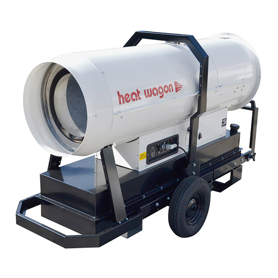
Installation and Maintenance Manual
Please retain this manual for future reference.
HVF110, 210, 310, 410HD
Construction
Heaters
C
US
For your safety: Do not use this heater in
a space where gasoline or other liquids
having flammable vapors are stored.
Revision 12-11
Advertisement

Related Manuals for Heat Wagon HVF210HD


Summary of Contents for Heat Wagon HVF210HD
- Page 1 342 N. Co. Rd. 400 East Valparaiso, IN 46383 219-464-8818 • Fax 219-462-7985 www.heatwagon.com Installation and Maintenance Manual Please retain this manual for future reference. HVF110, 210, 310, 410HD Construction Heaters For your safety: Do not use this heater in a space where gasoline or other liquids having flammable vapors are stored.
- Page 2 CONSTRUCTION HEATER GENERAL HAZARD WARNING TECHNICIAN. WARNING WARNING WARNING We cannot anticipate every use which may be made for our heaters. CHECK WITH YOUR LOCAL FIRE SAFETY AUTHORITY IF YOU HAVE QUESTIONS ABOUT LOCAL REGULA- TIONS. Other standards govern the use of fuel gases and heat producing products in specific applica- tions.
- Page 3 Accessories ..........25 WARRANTY All new Heat Wagon and Sure Flame heaters and fans are guaranteed against defective materials and work- manship for one (1) year from invoice date.
- Page 4 HVF110 HVF210 HVF310 HVF410HD 412/272 1020 3250 89.5 88.0 94.8 183.5 264.0 354/231 1.48 2.17 2.89/1.86 10.47 5.73 15.37 1,820 4.05 7.65 11.40 0.55-80º W 2.0-80º W 240/120 0.118 A=3.5, .196 5.90 0.05 0.05 0.05 0.05 17.2 27.7 35.7 49.3x20x33.3 56.5x21.9x38 83x33x48 56.5x21.9x38...
- Page 6 Reset Button Room Thermostat Plug Control Lamp Power Cord Main Switch Regulation of Electrodes HVF110 HVF210 HVF310 HVF410HD Note: 1/16” = 1.6 mm...
- Page 7 pg. 6 For additional details see advanced troubleshooting (page 8).
- Page 8 ADVANCED TROUBLESHOOTING Motor and transformer do not operate. Causes: 1. Incorrect or low voltage supplied to the heater. 2. Fuse in heater is blown. 3. Thermostat defective, or not turned up to call for heat. 4. Control board is defective. 5.
- Page 9 Motor runs, spark is present, but there is no fuel spray Causes: 1. Spray nozzle clogged. 2. Fuel pump is defective/or broken pump coupling 3. Air entering the fuel pump thru the inlet line. 4. Solenoid valve is defective. 5. Control board is defective. 6.
- Page 10 Motor runs, fuel sprays, but no spark is observed Causes: 1. Electrodes damaged or gapped incorrectly. 2. Transformer defective. 3. Control board defective. Solutions: 1. Electrodes damaged or gapped incorrectly. Inspect the electrode tips for melting. Make sure there are no cracks in the porcelain insulation. Check the electrodes with the manufacturer’s specifications for gapping and spacing.
- Page 11 Heater ignites, runs less than one minute and shuts down Causes: 1. Photocell is dirty, misaligned or defective. 2. Control board is defective. 3. Fuel pump defective. 4. Fuel filter dirty. Solutions: 1. Photocell is dirty, misaligned or defective. Check that the photocell is aimed correctly and is free of dirt. If necessary, clean the photocell “eye” with a soft, dry cloth.
- Page 12 5. Venting is improper. Follow the manufacturer’s recommendations concerning proper venting. Failure to do so can result in heat building up in the heater until the safety thermostat contacts open and shut the heater off. 6. Nozzle is dirty. If dirt reaches the nozzle, the spray can be adversely affected and cause a shut down. If possible observe the spray pattern and clean the nozzle as needed.
- Page 13 Heater ignites but flame is excessive Causes: 1. Fuel pump pressure is too high. 2. Nozzle is worn. 3. Incorrect fuel. Solutions: 1. Fuel pump pressure is too high. Attach a high pressure fuel gauge to the fuel pump and check the pump pressure. Adjust the pressure to the manufacturer’s specifications with the adjustment on the fuel pump.
- Page 15 HVF110 Electrical Schematic For SN 21100801 and Beyond...
- Page 16 HVF110 Breakdown Prior to SN 21100801...
- Page 17 HVF110 Parts List Prior to SN 21100801...
- Page 18 HVF110 Breakdown SN 21100801 to SN 21101000...
- Page 19 HVF110 Parts List SN 21100801 to SN 21101000 Photoresistence protection Box fixing bracket Switch support 100 Pa switch RV3 (110) Wiring Schematic For RV1 (210,310) Digital Thermostat RV (410) (Hot) RV1 (110) RV3 (210,310) Term #2 on Brahma (410)
- Page 20 HVF110 Breakdown For SN 21101001 and Beyond...
- Page 21 HVF110 Parts List For SN 21101001 and Beyond BFA01 R3 M20412 C30355 Photoresistence protection Box fixing bracket Switch support* I30696 100 Pa switch Solenoid valve cable 02AC508 G06361 * Note For SN 21101501 and Beyond Pos 38 - Base, PN G06405 - 9010 Pos 93 - Switch support, PN G06406-9010...
- Page 22 HVF210 Electrical Schematic For SN 21200801 to SN 21201201...
- Page 23 HVF310 Electrical Schematic Prior to SN 2131201 HVF210 Electrical Schematic Prior to SN 21200801 HVF110 Electrical Schematic Prior to SN 21100801...
- Page 24 HVF310 Electrical Schematic for SN 21301201 and Beyond HVF210 Electrical Schematic for SN 21201201 and Beyond...
- Page 25 Accessories EXTERNAL FUEL KIT THERMOSTAT FUEL CADDY (28 GALLONS) (allows access to #THIDF #PFC28 external fuel source) #TK300 DUCT ADAPTERS (ONE WAY) DUCT ADAPTERS (TWO WAY) DUCTING HVF110 #AR110 HVF210 #AR212 HVF110 - #WD1225 (12”X25’) HVF210 #AR210 HVF310 #AR312 HVF210 (2 WAY) - #WD1225 (12”X25’) HVF310 #AR310 HVF410HD #AR402 HVF310 (2 WAY) - #WD1225 (12”X25’)
- Page 26 HVF210 Breakdown Prior to SN 21200801...
- Page 27 HVF210 Parts List Prior to SN 21200801...
- Page 28 HVF210 Breakdown For SN 21200801 and Beyond...
- Page 29 HVF210 Parts List For SN 21200801 and Beyond Photoresistence protection Switch support* 100 Pa switch Solenoid valve cable C30323 Cable Protection * Note For SN 21201201 and Beyond Pos 40 - Base, PN G06407 - 9010 Pos 92 - Switch support, PN G06406-9010...
- Page 30 HVF310 Breakdown Prior to SN 21301201...
- Page 31 HVF310 Parts List Prior to SN 21301201 G06266 C30355 P20180-9005 I30698 G06107-9005 I25020 C30375 E10514...
- Page 32 HVF310 Breakdown SN 21301201 and Beyond...
- Page 33 HVF310 Parts List Photoresistence Protection Switch Support 100 Pa Switch...
- Page 34 HVF410HD Electrical Schematic Prior to SN 21800800...
- Page 35 HVF410HD Breakdown Prior to SN 21800800...
- Page 36 HVF410HD Parts List Prior to SN 21800800 Connection channel Photoresistence Protection Switch support 100 Pa switch...
- Page 37 HVF410HD Electrical Schematic SN 21800800 and Beyond...
- Page 38 HVF410HD Breakdown SN 21800800 and Beyond...
- Page 39 HVF410HD Parts List SN 21800800 and Beyond...
- Page 40 342 N. Co. Rd. 400 East Valparaiso, IN 46383 219-464-8818 • Fax 219-462-7985 www.heatwagon.com...
Need help?
Do you have a question about the HVF210HD and is the answer not in the manual?
Questions and answers