Advertisement
Quick Links
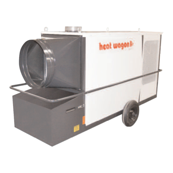
VG600
VF600
Construction
Heater
Revision 11-16
Installation and Maintenance Manual
Please retain this manual for future reference.
CAUTION: Do not use this heater in a
space where gasoline or other liquids
having flammable vapors are stored.
342 N. Co. Rd. 400 East
Valparaiso, IN 46383
888-432-8924 • Fax 219-462-7985
www.heatwagon.com
Advertisement

Subscribe to Our Youtube Channel
Related Manuals for Heat Wagon VG600


Summary of Contents for Heat Wagon VG600
- Page 1 342 N. Co. Rd. 400 East Valparaiso, IN 46383 888-432-8924 • Fax 219-462-7985 www.heatwagon.com Installation and Maintenance Manual Please retain this manual for future reference. VG600 VF600 Construction Heater CAUTION: Do not use this heater in a space where gasoline or other liquids having flammable vapors are stored.
- Page 2 If you need assistance or heater information such as an instruction manual, labels, etc., contact your local Heat Wagon dealer or the manufacturer. Fire, burn, inhalation, and explosion hazard. Keep solid combustibles, such as build- ing materials, paper or cardboard, a safe distance away from the heater as recom- mended by the instructions.
-
Page 3: Table Of Contents
Riello Burner ..........17-23 WARRANTY This heater is guaranteed against defective materials and workmanship for one (1) year from Heat Wagon invoice date. -
Page 4: Safety & Caution
• IF NOT OPERATED WITHIN GUIDELINES OF THESE OPERATING INSTRUCTIONS, MANUFACTURER WILL NOT BE HELD RESPONSIBLE AND WARRANTY WILL BECOME VOID. SPECIFICATIONS Model No. VG600 Fuels: Vapor Propane or Natural Gas Capacity: 600,000 BTU/HR Blower: 5400 CFM 3/4”... -
Page 5: Operating Instructions
OPERATING INSTRUCTIONS INSTALLATION • When transporting, use both lifting eyes located on sides of heater. • Place the unit on a level and non-combustible surface. • Minimum clearances from combustibles: - outlet, minimum 10 feet - sides, minimum 3 feet - top, minimum 3 feet - flue pipe exhaust minimum 2 feet •... - Page 6 FUEL SUPPLY (CONTINUED) • For proper propane tank sizing see page 9. • Visually inspect the hose assembly and ensure that it is protected from traffic, building materials, and contact with hot surfaces. If it is evident that there is excessive abrasion or wear, or the hose is cut, replace it immediately.
- Page 7 START UP • Only people trained in the operation and supervision of this heater should operate and maintain the unit. • Check the unit to make sure that there are no visible defects on the control and safety devices and that the unit has been installed correctly. 1.
-
Page 8: Maintenance
To ensure the proper function of the unit, it must be serviced on regular basis. Maintenance can be performed, excluding the control devices and safety limit controls, by an authorized trained & certified Heat Wagon dealer. The control devices and safety limit controls do not need routine maintenance. If these items fail they must be replaced. - Page 9 SERVICE • The complete unit, including heat exchanger, combustion chamber and burner should be cleaned from dust and dirt after every heating period, at a minimum of once per year. -Removal of combustion chamber/heat exchanger: For proper cleaning of the unit, manufacturer recommends removal of the access panel of the heat exchanger.
-
Page 10: Reference Charts
REFERENCE CHARTS... - Page 11 Propane Orifice Kit PN BIE 3000886 Natural Gas Orifice PN BIE 3006703...
-
Page 12: Exhaust Flue Pipe Guidelines
EXHAUST FLUE PIPE GUIDELINES VENT DIAMETER (D) INCHES CAPACITY OF TYPE B DOUBLE-WALL TOTAL VENTS SERVING A SINGLE DRAFT LATERAL VENT LENGTH HEIGHT( ( H H ) ) F HOOD-HEATER x 1000 BTU'S ( ( L L ) ) FEET 1170 FOR INDOOR APPLICATIONS 1320... - Page 13 WIRING CHART...
- Page 14 PARTS BREAKDOWN...
- Page 15 PARTS LIST ITEM # PART # DESCRIPTION 2077-10 BURNER CHAMBER ASSEMBLY 2077-50 BURNER PANEL 2077-51 BLOWER WALL 2077-52 WHEEL SHAFT 2077-53 HANDLE, SIDE 2077-63 ELECTRICAL BOX 2077-64 BURNER HOUSING COVER 2077-65 CONTROL PANEL 2077-71 BLOWER FLANGE 2077-72 SURFACE PLATE INLET NOzzLE NOT SHOWN 2077-130 BOTTOM PLATE BURNER 2077-135...
- Page 16 SPARE PARTS BREAKDOWN...
- Page 17 SPARE PARTS LIST Gas Pipe Train - Not Shown C5852400 Maxitrol Regulator (RV61) C5850607 ASCO Solenoid C5850017 Dungs Valve...
-
Page 18: Riello Burner
RIELLO BURNER - WIRING either 120V or 240V control systems. - Page 19 RIELLO BURNER - COMBUSTION HEAD...
- Page 20 RIELLO BURNER - AIR GATE...
- Page 21 RIELLO BURNER - COMBUSTION CHAMBER...
- Page 22 RIELLO BURNER - START-UP...
- Page 23 RIELLO BURNER - DIAGNOSTICS...
- Page 24 RIELLO BURNER - TROUBLESHOOTING...
- Page 25 VF600 OIL FIRED BURNER ELECTRODE SETTING...
- Page 26 VF600 OIL FIRED BURNER AIR ADJUSTMENT...
- Page 27 VF600 OIL FIRED BURNER PARTS BREAKDOWN...
- Page 28 342 N. Co. Rd. 400 East Valparaiso, IN 46383 219-464-8818 • Fax 219-462-7985 www.heatwagon.com...
Need help?
Do you have a question about the VG600 and is the answer not in the manual?
Questions and answers