
Related Manuals for Nu-Way MGN800-LN M3D


Summary of Contents for Nu-Way MGN800-LN M3D
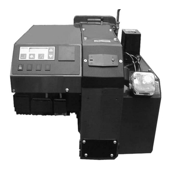
- Page 1 Installation & Maintenance Manual MGN 800 – LN SC Modulating Gas Burner Tel: +44 (0) 1905 794331 Fax: +44 (0) 1905 794017 Email: info@nu-way.co.uk Web: www.nu-way.co.uk...
-
Page 2: Table Of Contents
Contents General information ........................3 Checking scope of delivery and electrical data ................3 Maintenance and customer service ................... 3 Operating instructions ........................ 3 Instruction of operating personnel....................3 Filter/Strainer ..........................3 Key for code designation ......................4 Technical specifications ......................4 Boiler connection dimensions .................... -
Page 3: General Information
The boiler room must be ventilated accordingly with ventilation air. Nu-Way MGN800-LN M3D Series gas burners are suitable for combustion of natural gas or liquid gas in accordance with EN 437 and are in compliance with the EN 676 European standard. -
Page 4: Key For Code Designation
Burner output max Natural gas LL + E ="N" Series 8 Technical specifications Burner type Technical specifications MGN800-LN M3D Burner output in kW 225 - 860 Gas type Natural gas LL + E = "N" Mode of operation Progressive two-stage or modulating... -
Page 5: Mounting The Gas Jacket On The Boiler
10 Mounting the gas jacket on the boiler Air pressure connection Use adhesive to affix the gas-jacket gasket to the gas jacket. The boiler connection plate has to be prepared in ac- cordance with the sizes as stated in „9. Boiler connec- tion dimensions“. - Page 6 Cover See Circuit diagram The cover has to be removed and set to the service po- sition in order to permit access to the control unit. Re- move the securing screws (1) and fold the cover down to the left. Two-stage or modulating operation IMPORTANT ! The coding plug X85 with jack X86 must be connected...
-
Page 7: Air Flap Positioning Motor
13 Air flap positioning motor The air flap positioning motor is designed for air flap adju- stment on progressive two-stage burners or modulating burners. The motor is activated electronically via the microprocessor-controlled control box. Do not open the air flap positioning motor. The optics can become damaged irreparably. -
Page 8: Adjustment Of The Ignition Electrodes
17 Adjustment of the ignition electrodes MG1/MG2-LN The ignition electrodes are preset at the factory. Stauscheibe Zündelektrodenhalter Richtrohr Keramikkörper 2,5 - 3 mm (80) Abstand Keramikkörper 18 Flame control with Ionisation monitor In the presence of an alternating-current voltage between burner and ionisation rod, the rectifying effect of the flame causes a direct current to flow. -
Page 9: Control Unit Mpa 22
20 Control unit MPA 22 The MPA 22 is a microprocessor-controlled intermittent- duty control box for controlling and monitoring pneumatic modulating forced-air burners with an actuator drive. For operation as an automatic gas burner control with integral valve proving system. The MPA 22 has e-BUS connectivity. -
Page 10: Gas Train Kev Ii 1 ½" , Kev 2" And Kev Dn65
23 Gas train KEV 1 ½" , KEV 2" and KEV DN65 Installing the gas train Installation position only in horizontal line, not tilted. Minimum distance to walling 20 mm Screw the combustion chamber pressure measuring nipple into the gas jacket at the top (see "10 Mounting the gas jacket on the boiler"). -
Page 11: Gas Train Kev25 1", Kev30 1½", Kev45 2" And Kev45 Dn 65
23.a Gas train KEV25 1½" and KEV30 1" Installing the gas train Installation position only in horizontal line, not tilted. Minimum distance to walling 20 mm Screw the air pressure measuring nipple into the gas jacket at the top (see "10 Mounting the gas jacket on the boiler"). Route the connecting hose between the measuring nipple for combustion chamber pressure and the gas train in a loose loop. -
Page 12: Adjustment Mode - Pneumatic Gas-Fired Operation
24 Adjustment mode - pneumatic gas-fired operation To enter this adjustment mode, the burner must be on standby. Standby means that the burner is connected to the power supply, but no hea- ting request has been issued. If OFF appears on the display on MPA 22, the unit is running in standby mode and has already been configured. - Page 13 Step 6: After you have set P9, press the plus key to set P1. 1Gas appears on the dis- 1GAS play. The min load operating point can be adjusted to values between 0° and 90 ° by holding down key 2 and optionally pressing the plus or minus key. For basic setting values, please refer to the adjustment table.
-
Page 14: Calculation Principles For Gas Burner Adjustment
25 Calculation principles for gas burner adjustment The values given in the tables are setting values for start-up. The necessary system adjustment must be newly determined in each case. General: the calorific value (H ) of fuel gases is generally specified for the normal state (0°C, 1013 mbar). Natural gas type E = 10.4 kWh/m Natural gas type LL... -
Page 15: Adjustment Tables
The maximal burner output can only be achieved in mixing head position 0. Due to the variable mixing head position, the operating behaviour of the burner can be optimized for different heat generators.. MGN800-LN M3D = 9,3 [kWh/m Natural gas LL: H... -
Page 16: Troubleshooting
27 Troubleshooting Defect determined: Cause: Remedy: Fault code Burner motor does not start Electric supply lead faulty Rectify faults in electrical installation Fuse faulty Replace Safety thermostat locked Unlock 42 h Temperature of controller setting is Renewed start attempt after temperature exceeded drop MPA 22 faulty... - Page 17 Service mode - pneumatic gas-fired operation The service mode serves to display the set parameters and to read out the fault memory. It can be invoked in any operating state of the burner. Important: setting values cannot be changed in service mode. If no key is pressed for longer than 20 sec., the display returns to standby mode.
- Page 18 Troubleshooting the MPA Code Description 04 h Internal hardware fault 05 h Internal hardware fault 06 h Internal hardware fault 07 h Internal hardware fault 09 h Internal hardware fault 10 h Internal hardware fault 11 h Internal hardware fault 12 h Internal hardware fault 13 h...
-
Page 19: Troubleshooting / Process Description
Code Description Internal hardware fault Internal hardware fault Internal hardware fault Internal hardware fault 63 h Internal hardware fault 64 h Internal hardware fault 65 h Internal hardware fault 67 h Internal hardware fault 68 h Incorrect feedback from air flap positioning drive (check connector and cable, actuator drive mounting and air flap mechanism) Air-flap actuator position is out of tolerance (check connector and cable, actuator drive mounting and air flap mechanism) -
Page 20: Adjustments Log
28 Adjustments log Please enter the measured values into the Adjustments log. Boiler type Gas fitting Measured values min. max. Date P0 (start point) P1 (min load) P9 (max load) Flue gas temperature °C Carbon dioxide (CO level) content CO level Flue mbar Nozzle pressure... -
Page 22: Overall Dimensions
Enertech Limited, P O Box 1, Vines Lane Droitwich, Worcestershire, WR9 8NA Tel: +44 (0) 1905 794331 Fax: +44 (0) 1905 794017 Email: info@nu-way.co.uk Web: www.nu-way.co.uk...
Need help?
Do you have a question about the MGN800-LN M3D and is the answer not in the manual?
Questions and answers