
Related Manuals for Nu-Way MDFL 3300


Summary of Contents for Nu-Way MDFL 3300
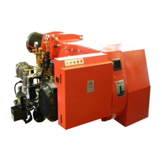
- Page 1 Installation & Maintenance Manual MDFL 3300 MDFL 4000 Dual Fuel Burner 11/12 Tel: +44 (0) 1905 794331 Fax: +44 (0) 1905 794017 Email: info@nu-way.co.uk Web: www.nu-way.co.uk...
-
Page 2: Table Of Contents
CONTENTS BURNER & COMPONENT INDENTIFICATION FOR MDFL 3300 & 4000 ………………………………… INTRODUCTION …………………………………………………………………………………………………... FEATURES ………………………………………………………………………………………………………… Burner Capacity ……………………………………………………………………………. Fuel ……………………………………………………………………………. Air Fan Size ……………………………………………………………………………. Controls and Safety Systems ……………………………………………………………………………. Operating Mode ……………………………………………………………………………. SITE CONDITIONS AND SERVICES ……………………………………………………………………………. Flue and Chimney Requirements ……………………………………………………………………………. - Page 3 In the UK it is a legal requirement that these engineers should also be CORGI registered. Nu-way cannot be held responsible for any consequential damage, loss or personal injury as a result of customers failing to follow these instructions, or as a result of misuse.
-
Page 4: Burner & Component Indentification For Mdfl 3300 & 4000
Single Spill-back Oil Nozzle Burners Models MDFL 3300 and 4000 Dimensions (mm) Model 1240 1196 MDFL 3300-36 1240 1196 MDFL 3300-41 1240 1210 MDFL 4000-36 1240 1210 MDFL 4000-41 1240 1210 MDFL 4000-44 MDFL 3300 & MDFL 4000 Issue 2 08/08 Page 3... - Page 5 BURNER MOUNTING ARRANGEMENT MGN 3300 & MGN 4000 Page 4 MODELS MDFL 3300 & 4000 BURNER MOUNTING ARRANGEMENT Hole Diameter: 350mm MDFL 3300 & MDFL 4000 Issue 2 08/08 Page 4...
-
Page 6: Introduction
(low and high) whilst gas firing. Continuous flame supervision is provided by an ultraviolet (UV) cell and automatic programming control unit. Operating Mode The MDFL 3300 and 4000 burners operate in fully modulating mode when firing on gas, and 2 stage (high/low) mode when firing on oil. Oil Firing – 2 stage Operation MDFL 3300 and 4000 burners are supplied with a system designated ‘Sliding High/Low’... -
Page 7: Site Conditions And Services
The gas supplier should be asked to recommend the size of pipework between the meter and the booster to ensure that the required pressure and flow are available. MDFL 3300 & MDFL 4000 Issue 2 08/08 Page 6... -
Page 8: Electrical Power Supply
Fuel Handling Temperatures (°C) (At Inlet to Burner Oil Pump) Viscosity Minimum Burner Fuel Class Atomising kg/cm (Seconds) From Tank Inlet Minimum 5 recommended 0.35 to 0.70 5.0 to 10.0 MDFL 3300 & MDFL 4000 Issue 2 08/08 Page 7... -
Page 9: Pumped Oil Ring Main
MUST also be fitted to prevent damage should the shut-off valve be inadvertently left closed during the burner start-up cycle. The relief valve must be set at 0.70 kg/cm (10 psi) above the normal supply pressure. MDFL 3300 & MDFL 4000 Issue 2 08/08 Page 8... -
Page 10: Unpacking And Assembly
These diagrams also show the external auxiliary control connections which must be made. If the burner is supplied as part of a packaged appliance/burner unit, refer to the appliance manufacturer’s instructions. MDFL 3300 & MDFL 4000 Issue 2 08/08 Page 9... -
Page 11: Burner Control And Operation
A manual isolation valve must be fitted at the inlet to the gas train during installation. This valve must be in the closed position when firing the burner on oil. MDFL 3300 & MDFL 4000 Issue 2 08/08 Page 10... -
Page 12: Air Damper Motor
5. The cam assembly can be rotated manually by disconnecting it from the drive motor using the disengagement lever. The cams are adjusted with the special ‘C’ spanner provided. MDFL 3300 & MDFL 4000 Issue 2 08/08 Page 11... -
Page 13: Gas Train
TYPICAL GAS TRAIN Item Description Item Description Manual Gas Interlock Valve Control Valve Low Gas Pressure Switch Pilot Solenoid Valve Main Valve Pilot Governor Valve Proving System High Gas Pressure Switch MDFL 3300 & MDFL 4000 Issue 2 08/08 Page 12... - Page 14 If necessary, a water trap must be provided. MDFL 3300 & MDFL 4000 Issue 2 08/08 Page 13...
- Page 15 Valve Proving System Valve proving systems are standard on all MDFL 3300 and 4000 burners. The standard model fitted is the Landis & Staefa LDU11. (See page 15) When the burner operating sequence is initiated the burner control box energises the proving system,...
- Page 16 VALVE PROVING SYSTEM : LDU 11 (Standard fitting) MDFL 3300 & MDFL 4000 Issue 2 08/08 Page 15...
-
Page 17: Oil Controls - Single Spill-Back Nozzle
MDFL burners use a single oil nozzle (see drg) within the inner assembly (refer to the Appendix). This nozzle is factory-specified to deliver optimum performance under the specified operating conditions. Any queries regarding the size of the nozzle should be referred to Nu-way. Fluidics W1 Nozzle The nozzle is held in position by the inner assembly lance, through which oil flows from the manifold block to the nozzle and recirculated through the spill regulating valve. - Page 18 OIL PUMPING SET FOR DISTILLATE FUELS Connection Sizes Size Item Description (inches) Main Inlet Connection Main Return Connection (Optional) Burner Feed ¾ Burner Return ¾ Mounting Dimensions Burner Model MDFL 3300 & MDFL 4000 MDFL 3300 & MDFL 4000 Issue 2 08/08 Page 17...
- Page 19 ¾” Vacuum gauge & ¼” Pressure gauge ¼” Regulator cap nut Washer Regulator screw Locknut Suntec TA Series Oil Pump Descriptions and sizing as for Series T pump shown above MDFL 3300 & MDFL 4000 Issue 2 08/08 Page 18...
- Page 20 2. Solenoid valves are shown as either NO (normally open) or NC (normally closed). 3. Pipework connections between the burner oil system and the separate pumping set are not supplied by Nu-way. See Note on Page 16. MDFL 3300 & MDFL 4000 Issue 2 08/08 Page 19...
-
Page 21: Control Panel
CONTROL PANEL On MDFL 3300 and MDFL 4000 burners the enclosure mounted on the left side of the burner serves mainly as a housing for electrical connections, although it also contains the ignition transformers and carries the burner On/Off switch, the Hand/Auto switch, and the Inching switch required by modulating burners. - Page 22 Lockout caused by the loss of the flame signal during normal operation. Lockout caused by flame signal (either real or due to extraneous light) or flame supervision circuit fault after completion of shutdown. MDFL 3300 & MDFL 4000 Issue 2 08/08 Page 21...
-
Page 23: Burner Operating Sequence
Note: The pre-purge times shown refer to the control box only. The time taken for the air damper to move to the appropriate position will extend the total purge time up to a maximum of 157 seconds, depending on the firing rate and air requirements of the appliance. MDFL 3300 & MDFL 4000 Issue 2 08/08 Page 22... -
Page 24: Modulating Controls
IP42. It is necessary to mount the water trap pipe supplied. General The detector must not be covered by lagging. Mounting instructions are printed on the packing. MDFL 3300 & MDFL 4000 Issue 2 08/08 Page 23... -
Page 25: Commissioning : General
In the UK, it is a legal requirement that anyone working on gas installations, as defined in the “Gas Safety (Installation and Use) Regulations 1994”, is CORGI registered. Nu-way can accept no responsibility for consequential loss, damage or injury which results from a failure to follow the commissioning instructions provided or from commissioning procedures being undertaken by unqualified personnel. -
Page 26: Initial Settings
IT MUST BE NOTED IN ALL CASES THAT WHEN OIL IS AVAILABLE TO THE BURNER THE UNIT MUST BE RE-COMMISSIONED ON BOTH FUELS. NOTICE SHOULD BE MADE OF THIS FACT, BOTH AT THE BURNER AND WITHIN THE BURNER HANDBOOK AND APPLIANCE LOG BOOK. MDFL 3300 & MDFL 4000 Issue 2 08/08 Page 25... -
Page 27: Commissioning : Oil
COMMISSIONING : OIL Burner Dry Run – MDFL 3300 & MDFL 4000 The following procedure should be followed. It is important that a complete and flawless dry run be completed before fuel is supplied to the system: Check that the gas, oil and electrical supplies to the burner are turned off. Turn the fuel selector switch on the control panel to the oil position. -
Page 28: Burner Live Run
Burner Live Run – MDFL 3300 & MDFL 4000 The instructions in this section are presented as a continuous sequence. No separate set of actions (for example, checking the flame signal) should be followed in isolation without paying particular attention to any safety precautions such as isolating the electrical supply to the burner which should precede such actions. - Page 29 When a satisfactory setting has been achieved, lock the air cam thumbscrews with the grubscrews fitted in the side face of the cam body. Refit the modulating cam unit access cover. Switch off the burner and the electricity supply to the burner. MDFL 3300 & MDFL 4000 Issue 2 08/08 Page 28...
- Page 30 MODULATING CAM BOX MDFL 3300 & MDFL 4000 Issue 2 08/08 Page 29...
-
Page 31: Commissioning : Gas
COMMISSIONING : GAS Burner Dry Run – MDFL 3300 & MDFL 4000 The following procedure should be followed. It is important that complete and flawless dry run be completed before fuel is supplied to the system: IT IS RECOMMENDED THAT THE BURNER SHOULD BE COMMISSIONED FOR OIL FIRING IN THE FIRST INSTANCE. -
Page 32: Burner Live Run
Burner Live Run – MDFL 3300 & MDFL 4000 The instructions in this section are presented as a continuous sequence. No separate set of actions (for example, checking the flame signal) should be followed in isolation without paying particular attention to any safety precautions such as isolating the electrical supply to the burner which should precede such actions. - Page 33 Adjust the low fire adjusting screw (2) to bring the CO level to an acceptable level. MDFL 3300 & MDFL 4000 Issue 2 08/08 Page 32...
- Page 34 Turn the adjusting dial on the pressure switch clockwise one small step at a time until the switch trips, causing the burner to shut down. Turn the adjusting dial anti-clockwise until main flame can be established. MDFL 3300 & MDFL 4000 Issue 2 08/08 Page 33...
-
Page 35: Final Commissioning Stages - Oil And Gas
Switch off the burner and the electrical power supply to the burner. Remove the manometer, if fitted. Replace the pressure switch cover. Remove the control panel cover and replace the low fire hold link. Replace the cover. MDFL 3300 & MDFL 4000 Issue 2 08/08 Page 34... -
Page 36: Modulating Control : Siemens Rwf 40
Switch on Hys 1 threshold Reduce value Increase value Upper off Hyst 3 99.9 999.9 threshold PGM key Exit key Detector: EXIT range start Detector: Landis & Staefa RWF40 range end MDFL 3300 & MDFL 4000 Issue 2 08/08 Page 35... -
Page 37: Final Checks
The actions to be taken in the event of a fault condition. Clear light-up and shutdown procedures are displayed on the plant and that the pipes, valves and switches involved are clearly marked. CLEAR AND CONCISE EMERGENCY SHUTDOWN PROCEDURES ARE DISPLAYED. MDFL 3300 & MDFL 4000 Issue 2 08/08 Page 36... -
Page 38: Full Changeover Procedure
Re-tighten the screw in the pressure test point and reset the lockout button on the valve proving system. MDFL 3300 & MDFL 4000 Issue 2 08/08 Page 37... -
Page 39: Routine Maintenance
If the filter element is re-usable it should be cleaned at appropriate intervals. After filter cleaning operations it will be necessary to remove air from the system by bleeding the pump. MDFL 3300 & MDFL 4000 Issue 2 08/08 Page 38... -
Page 40: Fault Finding
Clean or replace 2. Check that the booster drive belt is fitted. Nozzle blocked Clean or replace 3. Verify that the booster motor is rotating correctly. Carbon on diffuser Clean MDFL 3300 & MDFL 4000 Issue 2 08/08 Page 39... -
Page 41: Start Flame Failure
Air setting incorrect Reset SPARE PARTS For spare parts contact Nu-way’s Parts and Components Division at the address and telephone number listed on the rear cover of this manual. To avoid delays, please provide the burner model, serial and specification numbers. -
Page 42: Appendix
Blank ‘Notes’ page to allow the user to make any relevant notes, comments or other relevant information. Burner Head Details Burner Head Dimensions Dimensions Model No. E MDFL 3300-36 12.7 MDFL 3300-41 12.7 MDFL 4000-36 12.7 MDFL 4000-41 12.7 MDFL 4000-44 12.7 MDFL 3300 & MDFL 4000 Issue 2 08/08 Page 41... -
Page 43: Electrode Setting Detail
Electrode Setting Details All dimensions in mm MDFL 3300 & MDFL 4000 Issue 2 08/08 Page 42... -
Page 44: Performance Envelopes
Performance Envelopes : MDFL 3300 and MDFL 4000 MDFL 3300 MDFL 4000 MDFL 3300 & MDFL 4000 Issue 2 08/08 Page 43... -
Page 45: Oil Commissioning Sheet
Basis °C or Flue Temp. °F °C or Ambient Temp. °F °C or Temp. Difference °F Efficiency Note: where a choice of measurement units is shown, delete those not applicable, MDFL 3300 & MDFL 4000 Issue 2 08/08 Page 44... -
Page 46: Gas Commissioning Sheet
Basis °C or Flue Temp. °F °C or Ambient Temp. °F °C or Temp. Difference °F Efficiency Note: where a choice of measurement units is shown, delete those not applicable, MDFL 3300 & MDFL 4000 Issue 2 08/08 Page 45... -
Page 47: Burner Service Record
BURNER SERVICE RECORD The details below are to be completed by the Servicing Engineer This sheet to be completed and signed following each service/adjustment Date Details of Service Signature MDFL 3300 & MDFL 4000 Issue 2 08/08 Page 46... -
Page 48: Notes
NOTES MDFL 3300 & MDFL 4000 Issue 2 08/08 Page 47... - Page 49 Enertech Limited, P O Box 1, Vines Lane Droitwich, Worcestershire, WR9 8NA Tel: +44 (0) 1905 794331 Fax: +44 (0) 1905 794017 Email: info@nu-way.co.uk Web: www.nu-way.co.uk...
Need help?
Do you have a question about the MDFL 3300 and is the answer not in the manual?
Questions and answers