
Subscribe to Our Youtube Channel
Related Manuals for Nu-Way MOL 3400-410


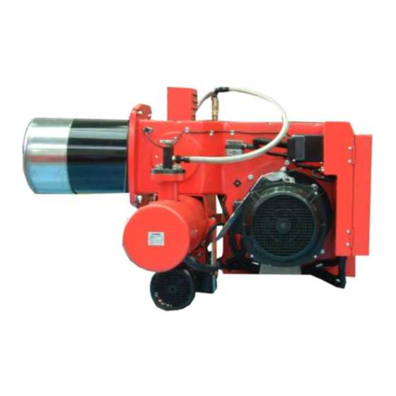
Summary of Contents for Nu-Way MOL 3400-410
- Page 1 Installation & Maintenance Manual MOL 3400-4100 Oil Burner Tel: +44 (0) 1905 794331 Fax: +44 (0) 1905 794017 Email: info@nu-way.co.uk Web: www.nu-way.co.uk...
-
Page 2: Table Of Contents
CONTENTS BURNER & COMPONENT IDENTIFICATION FOR MOL 3400 & 4100 BURNERS …………………………… INTRODUCTION …………………………………………………………………………………………………... FEATURES …………………………………………………………………………………………………………… Burner Capacity ……………………………………………………………………………. Controls and Safety Systems ……………………………………………………………………………. Operating Mode ……………………………………………………………………………. Fuel ……………………………………………………………………………. SITE CONDITIONS AND SERVICES ………………………………………………………………………………. Flue and Chimney Requirements ……………………………………………………………………………. Plant Room Ventilation ……………………………………………………………………………. - Page 3 In the UK it is a legal requirement that these engineers should also be CORGI registered. Nu-way cannot be held responsible for any consequential damage, loss or personal injury as a result of customers failing to follow these instructions, or as a result of misuse.
-
Page 4: Burner & Component Identification For Mol 3400 & 4100 Burners
BURNER AND COMPONENT IDENTIFICATION FOR HIGH/LOW BURNERS All dimensions are in mm * Standard projections 240, 340, 430 Oil pump unit Item Description Burner Casing Flame Tube Fan Motor Air Inlet Control Panel Fan Inspection Cover Ignition Transformer 545 / 640 (See Note) Note: 545 for MOL 3400-36 only) These dimensions are intended for general assessment of the overall sizes of the burners and should not be used... - Page 5 BURNER AND COMPONENT IDENTIFICATION FOR MODULATING BURNERS All dimensions are in mm MOL 3400-4100 Issue 2 10 /08 Page 4...
- Page 6 BURNER AND COMPONENT IDENTIFICATION FOR MODULATING BURNERS Burner Mounting Details Item Description Burner Casing Hinged Extension Flame Tube Fan Motor Air Inlet Modulating Control Motor Control Panel Modulating Cam Unit Oil Spill Control Valve Burner Head Oil Inlet Quick Release Connection Burner Head Return Oil On request, MOL modulating burners can Quick Release Connection...
- Page 7 Electrical Data MOL 3400 & 4100 Modulating and High/Low Burners Control MCB is 6 Amp in all cases Control Fan Motor Main Burner MCB Size Fan Motor MCB Size Overload Cable Size MOL 3400-36 6 Amp 7.5 kW 3 x 20 Amp 11-16 Amp MOL 3400-41 6 Amp...
-
Page 8: Introduction
INTRODUCTION This manual has been produced to enable users to install, commission and use MOL modulating burners safely and efficiently. The manual covers two types of burner: High/Low and Modulating (Class D fuel). At each stage the conditions which should be met and the adjustments and other actions which should be carried out are detailed and the locations of the various components and adjustment mechanisms are identified. -
Page 9: Combustion Chamber Conditions
(PRV) should be fitted to control the supply pressure. Burner Pump Capacities The oil pumps used on Nu-way modulating oil burners are listed in the table on page 26. It is essential that the full swept volume of the pump be considered when oil supply lines or ring main systems are calculated. -
Page 10: Unpacking And Assembly
UNPACKING and ASSEMBLY To safeguard against damage in transit, MOL modulating burners may be supplied in partly assembled form in one of three alternative modes: Mode 1: The complete burner unit fully assembled. Mode 2: Burner body complete with control panel. Combustion head hinged extension and flame tube assembly. -
Page 11: Modulating Burner Oil System
BURNER OIL SYSTEM Pumped Systems – All Modulating Burners All interconnecting pipework to be minimum 19mm and pressure rated for 42 kg/cm (600 psi). All burners require a pump inlet pressure of 0.35 to 0.70 kg/cm (5 to 10 psi). If a shut-off valve is fitted in the inlet line, a pressure relief valve set at 0.7 kg/cm (10 psi) above the supply pressure must be fitted to prevent damage should the valve be left shut during burner. -
Page 12: Installation
INSTALLATION General Ensure that the appliance is suitable for the heat input of the burner. If there is any doubt in this area, reference shall be made to the appliance manufacturer. Detailed burner performance data are presented in the appendix of this handbook. Fitting to the Appliance If the burner is to be fitted to a new appliance refer to the appliance manufacturers recommendations. -
Page 13: Burner Control Operation - Modulating & High/Low
BURNER OPERATION - MODULATION Burner Description Nu-way MOL modulating series fully automatic oil burner units are of packaged design and meet relevant National and International standards based on the ISO system of measurement and fastening. A system of pressure atomisation employing a single spill-back nozzle is used throughout the range. If the burner is equipped with the Nu-way Electronic Cam Modulating (ECM) system, then reference should also be made to the supplementary documentation supplied with this handbook. -
Page 14: Burner Controls
BURNER CONTROLS Burners are supplied with an integral control panel containing a sequencing control unit and the burner switchgear. On steam boiler applications an auxiliary control panel containing boiler feed pump controls, water level interlocks and alarms is available. Oil Pumping Units Standard burners are supplied with a floor-mounted pumping unit. -
Page 15: Commissioning : General
In the case of MOL modulating burners, commissioning engineers should be experienced in pressure jet oil burner commissioning. Nu-way can accept no responsibility for consequential loss, damage or personal injury which results from a failure to follow the commissioning instructions provided or from commissioning procedures being undertaken by unqualified personnel. -
Page 16: Pre-Firing Checks
Pre-firing Checks and Dry Run With the oil and power switched off, carry out the following checks: Check the nozzle size and position relative to the diffuser plate. (The burner head dimensional details are given in the appendix of this handbook). Check that the electrode positions and HT leads are correct. -
Page 17: Commissioning : Modulating
THE BURNER IS NOW READY TO BE COMMISSIONED COMMISSIONING - MODULATING BURNER Hand Auto Selector Switch This switch must always be in the ‘Auto’ position when the burner is required to start. The ‘Hand’ selection can be made immediately the burner has started to fire. Should the burner be left in the ‘Hand’... -
Page 18: Modulating Unit
MODULATING UNIT (Cams shown in the Low Flame Position) MOL 3400-4100 Issue 2 10/08 Page 17... - Page 19 Check the oil consumption. If this is not correct for the full burner rating, the oil cam must be adjusted as follows:- a. Inch the burner to low flame and note the spill pressure b. To increase the minimum rate, adjust as shown in fig.1. c.
-
Page 20: Commissioning : High/Low
COMMISSIONING - HIGH/LOW BURNER LOW FLAME Switch on electricity supply. If controls are correctly set, burner fan will start, followed by oil pump, providing air pressure switch changes over. Check rotation of each. Air pressure switch is works set at 50mm wg, but may have to be adjusted to suit installation. After pre-purge period has elapsed the low flame solenoid valve will open allowing oil to spray through the low flame nozzle only and be ignited by the HT spark which is already present. -
Page 21: Final Checks - Commissioning
FINAL CHECKS Check that all covers have been replaced and that all locking devices are secure. Check the operation of the appliance control instruments and safety interlocks. Ensure that the appliance safety controls and any other interlocks are set to safe limits. COMMISSIONING IS NOW COMPLETE. -
Page 22: Routine Maintenance
ROUTINE MAINTENANCE OF MOL BURNERS General It is vitally important that personnel responsible for the day to day operation and maintenance of the plant are instructed by the commissioning engineer on the basic function of the burner, as well as the need for routine maintenance and daily checking of burner operations. -
Page 23: Inner Assembly Removal - Modulating
Inner Assembly Removal – Modulating Burners Switch off the electricity supply to the burner and disconnect the flexible oil lines at the burner head quick release couplings. Remove the hinge plate retaining nuts and swing open the burner. Disconnect the HT leads and remove the two long cap head screws retaining the inner assembly, from the face of the oil manifold block on the side of the hinged extension. -
Page 24: Fault Finding
FAULT FINDING If the Burner Fails to Start Make sure that all the thermostats and switches in the control circuit are in the ‘made’ position and that the oil pre-heater ‘excess limit’ thermostat has not tripped. Reset if required. Check that the low oil temperature thermostat is set correctly for the appropriate fuel. -
Page 25: Burner Head Details & Electrode Setting
BURNER HEAD DETAILS & ELECTRODE SETTING MODULATING HIGH/LOW MOL 3400-4100 Issue 2 10/08 Page 24... -
Page 26: Fuel Pumps - Suntec
FUEL PUMPS Suntec Series TV Pressure Regulating Valve (For use with Suntec series ‘T’ pumps) The TV valve is designed for use with the Suntec series ‘T’ fuel pumps, see diagrams. This separate pressure-regulating valve, which is installed in the nozzle line, is designed to keep constant pressure even if the output capacity is changed. -
Page 27: Hp Technik
HP TECHNIK VBGR OIL PUMP Technical data Special Model with SC quick-release *e2 nozzle connection R, S & A pipe connections = ½” BSP Note VBGR is for two-pipe application. Used as one-pipe pump with positive feed pressure an external bypass has to be made between the return port and the suction port. -
Page 28: Flame Failure & Sequence Control & Modulating Control Systems
FLAME FAILURE & SEQUENCE CONTROL – Siemens LAL.1 Burner Control The unit is designed to provide control and supervision for atomising oil burners of medium to large capacity. They are suitable for use on multi-stage and modulating burners. For safety reasons, at least one controlled shutdown must be provided within each 24-hour period of continuous operation. - Page 29 Control Program under Fault Conditions and Lockout Indication In the event of fault conditions the sequence switch stops and simultaneously the lockout indicator. The symbol appearing above the reading mark indicates the kind of fault encountered. a - b Start-up sequence b - b’...
- Page 30 Modulating Control : Siemens RWF 40 Basic display The diagram below shows the RWF40 after switching on the supply voltage. This conditions is called the basic display. The actual valve and the currently active set-pint are shown here. Manual operation, self- optimisation, the operating parameter and configuration levels can be activated from here.
- Page 31 FLAME FAILURE & SEQUENCE CONTROL – Satronic TMO 720-4 Burner Control The unit is designed to provide control and supervision for atomising oil burners of medium to large capacity. For safety reasons, at least one controlled shutdown must be provided within each 24-hour period of continuous operation.
-
Page 32: Burner Oil Nozzle
Should it become necessary to order replacement parts, it is important to quote the burner model, specification and serial numbers to ensure correct expedition of your order. Nu-way Limited is able to offer ‘on site’ Commissioning, Service and Repair through its worldwide network of authorised distributors and sales offices. -
Page 33: Appendix
APPENDIX Burner Performance Graph All outputs quoted are based on nett CV The performance graph shown above plots burner input against the appliance running resistance. The appliance starting resistance is derived from a combination of the combustion chamber shape, volume, start rate and flue conditions. -
Page 34: Commissioning Sheet
COMMISSIONING SHEET The details below are to be completed by the Commissioning Engineer Installers Name: ___________________________________________________________________________ Address: ____________________________________________________________________________ ____________________________________________________________________________ Site Address: ____________________________________________________________________________ ____________________________________________________________________________ Appliance: Type:___________________ Rating:____________________ Serial No:________________ Burner: Type:___________________ Rating:____________________ Spec No:_________________ Serial No:_______________ Nozzles:___________________ Oil Pump:________________ Commissioning date: ______________________ Guarantee Expiry Date: _______________________ Oil type: _________________________________ Point... - Page 35 NOTES...
- Page 36 NOTES...
- Page 37 Enertech Limited, P O Box 1, Vines Lane Droitwich, Worcestershire, WR9 8NA Tel: +44 (0) 1905 794331 Fax: +44 (0) 1905 794017 Email: info@nu-way.co.uk Web: www.nu-way.co.uk...
Need help?
Do you have a question about the MOL 3400-410 and is the answer not in the manual?
Questions and answers