
Subscribe to Our Youtube Channel
Related Manuals for Nu-Way ST 40


Summary of Contents for Nu-Way ST 40
- Page 1 Installation & Maintenance Manual ST 40 Oil Burner 11/12 Tel: +44 (0) 1905 794331 Fax: +44 (0) 1905 794017 Email: info@nu-way.co.uk Web: www.nu-way.co.uk...
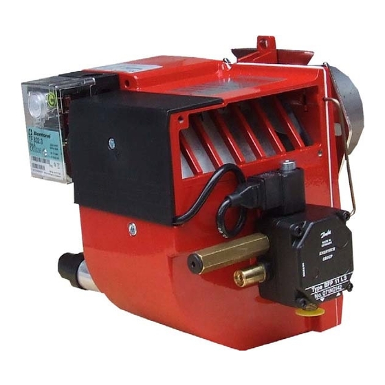
- Page 2 DESCRIPTION COMPONENTS 1. Reset button 8. Blast tube 14. Drive coupling 2. Control box 9. Ignition electrodes 15. Indication, air damper 3. Ignition transformer 10. Connecting pipe 16. Fan wheel 4. Ignition cables 11. Air damper 17. Adjustment, air damper 5.
-
Page 4: Technical Data
TECHNICAL DATA DIMENSIONS Flange C Flange A ø89,7 ø90 130-150 Flange D Flange B ø90 ø89,5 136-150 125-150 171 215 76 99-01... -
Page 5: General Instructions
GENERAL INSTRUCTIONS GENERAL RULES MAINTENANCE Increase the oil quantity The installation of an oil burner should The boiler/burner should be exami- Raise the flue gas temperature by be carried out in accordance with local ned regularly for any signs of malfunc- removing turbulators, if any, in the regulations. - Page 6 MAINTENANCE OF OIL BURNER Warning: Before doing any service switch off power at the main switch and cut off the oil supply. SERVICE OF BURNER HEAD AND NOZZLE ASSEMBLY 171 305 68 94-01...
- Page 8 INSTRUCTIONS PUMP TYPE DANFOSS BFP11 TECHNICAL DATA Viscosity range: 1,3-12,0 mm Pressure range: 7-15 bar Oil temperature: -10 to +70°C COMPONENTS 1. Nozzle port R 1/8" 2. Pressure gauge port 3. Pressure adjustment, 4mm allen key 5. Vacuum gauge port R 1/8" 6.
- Page 9 FUNCTION DANFOSS BFP11 When the oil pump is started, oil is drawn from the suction connection (S) through the filter (H) to the suction side of the gear wheel (C). The gear wheel then pumps oil to the pressure side and the oil is put under pressure.
- Page 10 Pump pressure bar NOZZLE TABLE kg/h kW Mcal/h kg/h kW Mcal/h kg/h kW Mcal/h kg/h kW Mcal/h kg/h kW Mcal/h kg/h kW Mcal/h kg/h kW Mcal/h kg/h kW Mcal/h 0,40 1,33 1,41 1,49 1,56 1,63 1,70 1,76 1,82 0,50 1,66 1,76 1,86 1,95...
-
Page 11: Fault Location
FAULT LOCATION BURNER FAILS TO START Situation Possible causes Remedies Motor runs Flame instabillity Check nozzle to burner head dimension and Incorrect head settings Burner pre-purges electrode position Check oil pressure Low oil pressure Adjust air damper Flame occurs Excess air Burner locks out Photocell not seeing light Check that photocell is clean and unobstructed... - Page 12 NOTES...
- Page 13 NOTES...
- Page 14 Enertech Limited, P O Box 1, Vines Lane Droitwich, Worcestershire, WR9 8NA Tel: +44 (0) 1905 794331 Fax: +44 (0) 1905 794017 Email: info@nu-way.co.uk Web: www.nu-way.co.uk...
Need help?
Do you have a question about the ST 40 and is the answer not in the manual?
Questions and answers