
Related Manuals for Nu-Way MDFL 1880


Summary of Contents for Nu-Way MDFL 1880
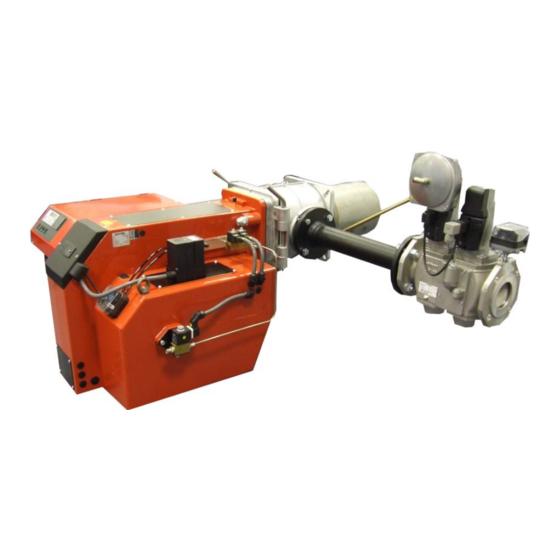
- Page 1 Installation & Maintenance Manual MDFL 1510 MDFL 1880 MDFL 2505 MDFL 2705 Dual Fuel Burner 11/12 Tel: +44 (0) 1905 794331 Fax: +44 (0) 1905 794017 Email: info@nu-way.co.uk Web: www.nu-way.co.uk...
-
Page 2: Table Of Contents
Contents 1. General information ......................3 2. Scope of delivery ........................3 3. Maintenance and customer service..................3 4. Operating instructions ......................3 5. Instruction of operating personnel ..................3 6. Filter/Strainer ........................3 7. Key for code designation ..................... 4 8. -
Page 3: General Information
European standard EN 676 and EN 267. 2. Scope of delivery Before installing the Nu-Way Series MDFL1510/2705 dual fuel, please check that all the items included in the scope of delivery are present. Scope of delivery: burner, mounting kit, separate operating instructions, technical information, separate circuit diagram, flange seal, one 7- pin connector and one 4- pin plug connector (Wieland connector). -
Page 4: Key For Code Designation
7. Key for code designation MDFL1510 Burner output max. Series 8. Technical specifications Burner type Technical specifications MDFL1510 MDFL1880 MDFL2505 MDFL2705 Burner output in kW 441 - 1510 738 - 1880 620 - 2505 887 - 2705 (in gas-fired operation) Burner output (in oil-fired operation) in kg/h 46.2 - 127.3... -
Page 5: Ignition Electrode
10. Ignition electrode The following clearances between the nozzle and ignition electrode should be observed: The given dimensions are intended for checking purposes after making necessary corrective adjustments or replacing an electrode. ignition electrode gas ignition electrode oil 11. Flame failure controller Operating Indicator LED: LED is OFF: KLC is not switched on –... -
Page 6: Oil Connection
If any of these safety checks do not function as described i.e. they should always result in burner shutdown and control box lock-out; then it is essential to replace the flame detector with a new KLC flame detector. For safety and trouble free burner operation, we recommend that the flame detector should be replaced after every 10,000 hours of burner operation or approximately every 30months for a burner operating on an average of 10 hours per day. - Page 7 Single-pipe system Nozzle 14 (gph) 20 (gph) 30 (gph) 45 (gph) .∅ mm H (m) L (m) L (m) L (m) L (m) L (m) L (m) L (m) L (m) L (m) L (m) L (m) L (m) L (m) L (m) L (m) -0.5...
-
Page 8: Oil Pump
13. Oil pump Oil lines must be routed to the burner as far as necessary to allow the oil hoses to be connected without tension. Care must be taken to ensure that the burner can easily be moved into the service position. Important: an oil filter must be installed before the oil pump. -
Page 9: Front Panel
15. Front panel Controller (option) On/Off Display and operating unit AM01 Selector switch Oil operation/gas-fired operation 16. Air flap positioning motor The air flap positioning motor is designed for air flap adjustment on progressive two-stage burners or mod- ulating burners. The motor is activated electronically via the microprocessor-controlled control box. -
Page 10: Air Pressure Switch
18. Air pressure switch The air pressure switch is a differential pressure switch and monitors pressure at the forced-air burner. The air pressure switch is preset at the factory to 8 mbar. 19. Gas pressure monitor The gas pressure monitor serves to monitor the gas inlet pressure. The burner is shut down if the gas inlet pressure drops below the set minimum value (preset at factory). - Page 11 21. Commissioning: Adjustment mode - oil-fired operation To enter this adjustment mode, the burner must be on standby. Standby means that the burner is connected to the power supply, but no heat- ing request has been issued and the burner is switched to oil-fired operation. If OFF appears on the display on MPA 22, the unit is running in standby mode and has already been configured.
- Page 12 Step 6: 3 OIL After you have set Stage 3, press the plus key to set Stage 2 . 3OIL appears on the display. The Stage 2 operating point can be adjusted to values between 0° and 90° by holding down key 2 and optionally pressing the plus or minus key. For basic setting values, please refer to the adjustment table.
- Page 13 Adjustment mode - gas-fired operation To enter this adjustment mode, the burner must be on standby. Standby means that the burner is connected to the power supply, but no heat- ing request has been issued and the burner is switched to gas-fired operation. If OFF appears on the display on MPA 22, the unit is running in standby mode and has already been configured.
- Page 14 Step 6: 1GAS After you have set P9, press the plus key to set P1. 1 Gas appears on the dis- play. The min load operating point can now be set to a value between 0° and 90° by holding down key 2 and optionally pressing the plus or minus key. For basic setting values, please refer to the adjustment table.
-
Page 15: Troubleshooting / Process Description
22. Troubleshooting / process description Defect determined: Cause: Remedy: Fault code Burner motor does Electric supply lead faulty Rectify faults in electrical installation not start up Fuse faulty Replace Safety thermostat locked Unlock 42 h Temperature of controller setting is Renewed start attempt after temperature exceeded drop... - Page 16 Service mode - pneumatic gas-fired operation The service mode serves to display the set parameters and to read out the fault memory. It can be invoked in any operating state of the burner. Important: setting values cannot be changed in service mode. If no key is pressed for longer than 20 sec., the display returns to standby mode.
- Page 17 Troubleshooting the MPA Code Description 04 h Internal hardware fault 05 h Internal hardware fault 06 h Internal hardware fault 07 h Internal hardware fault 09 h Internal hardware fault 10 h Internal hardware fault 11 h Internal hardware fault 12 h Internal hardware fault 13 h...
- Page 18 Code Description Internal hardware fault Internal hardware fault Internal hardware fault Internal hardware fault 63 h Internal hardware fault 64 h Internal hardware fault 65 h Internal hardware fault 67 h Internal hardware fault 68 h Incorrect feedback from air flap positioning drive (check connector and cable, actuator drive mounting and air flap mechanism) Air-flap actuator position is out of tolerance (check connector and cable, actuator drive mounting and air flap mechanism)
-
Page 19: Control Unit
23. Control unit MPA 22 The MPA 22 is a microprocessor-controlled intermittent- duty control box for controlling and monitoring pneumatic modulating forced-air burners with an actuator drive. For operation as an automatic gas burner control with integral valve proving system. The MPA 22 has e-BUS connectivity. -
Page 20: Calculation Principle For Gas Burner Adjustment
25. Calculation principles for gas burner adjustment The values given in the tables are setting values for start-up. The necessary system adjustment must be newly determined in each case. General: the calorific value (H ) of fuel gases is generally specified for the normal state (0°C, 1013 mbar). -
Page 21: Gas Train Kev Ii 1 ½" , Kev 2" And Kev Dn65
26. Gas train KEV 1 ½" , KEV 2" and KEV DN65 Installing the gas train Installation position only in horizontal line, not tilted. Minimum distance to walling: 20 mm Screw the measuring nipple for combustion chamber pressure into the gas jacket at the top. Route the connecting hose between the measuring nipple for combustion chamber pressure and the gas train in a loose loop. -
Page 22: Gas Train Kev25 1" And Kev30 1½
27. Gas train KEV25 1" and KEV30 1½" Installing the gas train Installation position only in horizontal line, not tilted. Minimum distance to walling: 20 mm Screw the air pressure measuring nipple into the gas jacket at the top. Route the connecting hose between the air pressure measuring nipple and the gas train in a loose loop. The air pressure connection nipple must be screwed into the gas jacket at the top. -
Page 23: Nozzle Selection Diagram
28. Nozzle selection diagram If the desired output deviates from the values specified in the tables, the nozzle size and the pump pressure can be determined on the basis of the following diagram. Öl- Nozzle Burner durch- Brenner- Düsen- size throughput output satz... -
Page 24: Adjustment Tables
29. Adjustment table... -
Page 26: Exploded Views / Spare Parts Lists
30. Exploded views / spare parts lists Oil pump unit MDFL Item Designation Art. No. Motor 1.1 kW 50 Hz 36-90-11538 Coupling compl. for pump unit MDFL 47-90-27103 Pressure switch compl. with cable 47-90-25363 T-piece compl. for pump unit 44-90-23080 Sealing washer AL 14 x 10 x 2 37-50-10788 Pressure pipe nipple... - Page 27 Combined gas/oil burner MDFL1510, MDFL1880...
- Page 28 Item Designation Art. No. Burner pipe MDFL1510, MDFL1880 47-90-25392 Burner pipe MDFL1510, MDFL1880, extended 200 mm 47-90-25442 Mixing head MDFL1510, MDFL1880 welded 47-90-27091 Mixing head MDFL1510, MDFL1880 welded, extended 200 mm 47-90-27092 Baffle plate MDFL1510, MDFL1880 47-90-25088 Oil ignition electrodes compl. 47-90-26213 Oil / gas ignition cable set 47-50-25003...
- Page 29 Item Designation Art. No. Base CR-PLSx 47-90-26713 Relay CR-P230AC2 47-90-25199 Base CR-M4LS 47-90-26731 Relay CR-M230AC4 47-90-25181 Remote-manual switch 47-90-25040 Thermal overload relay for pump unit 2.4 - 4 A 47-90-25172 Mini motor contactor B7-30-10 for pump unit 47-90-25171 Ignition transformer Fida Mod. 26/35 incl. ignition cable 200 mm lg. 47-90-26790 Ignition transformer Fida Mod.
- Page 30 Combined gas/oil burner MDFL2505, MDFL2705...
- Page 31 Item Designation Art. No. Burner pipe MDFL2505, MDFL2705 47-90-25393 Burner pipe MDFL2505, MDFL2705, extended 200 mm 47-90-25443 Mixing head MDFL2505, MDFL2705 welded 47-90-27097 Mixing head MDFL2505, MDFL2705 welded, extended 200 mm 47-90-27098 Baffle plate MDFL2505, MDFL2705 47-90-25238 Oil ignition electrodes compl. 47-90-26213 Oil / gas ignition cable set 47-50-25003...
- Page 32 Item Designation Art. No. Relay CR-P230AC2 47-90-25199 Base CR-PLSx 47-90-26713 Base CR-M4LS 47-90-26731 Relay CR-M230AC4 47-90-25181 Remote-manual switch 47-90-25040 Thermal overload relay for pump unit 2.4 - 4 A 47-90-25172 Mini motor contactor B7-30-10 for pump unit 47-90-25171 Ignition transformer Fida Mod. 26/35 incl. ignition cable 200 mm lg. 47-90-26790 for MDFL2505, MDFL2705 Ignition transformer Fida Mod.
-
Page 33: Adjustments Log
31. Adjustments log Please enter the measured values into the Adjustments log. Boiler type Gas fitting Measured values min. max. Date P0 (start point) P1 (min load) P9 (max load) Flue gas temperature °C Carbon dioxide (CO level) content CO level Flue mbar Nozzle pressure... -
Page 34: Declaration Of Conformity For Dual-Fuel Burner For Heating Oil And Natural Gas Or Liquid Gas
32. Declaration of conformity for dual-fuel burner for heating oil EL and natural gas or liquid gas We, Enertech GmbH, D-58675 Hemer, hereby declare on its own responsibility that the products MDFL ... are in conformity with the following standards and regulations: EN 267 EN 676 EN 50081... -
Page 36: Overall Dimensions
Enertech Limited, P O Box 1, Vines Lane Droitwich, Worcestershire, WR9 8NA Tel: +44 (0) 1905 794331 Fax: +44 (0) 1905 794017 Email: info@nu-way.co.uk Web: www.nu-way.co.uk...
Need help?
Do you have a question about the MDFL 1880 and is the answer not in the manual?
Questions and answers