Table of Contents
Advertisement
Quick Links
Advertisement
Table of Contents

Related Manuals for Nu-Way G100


Summary of Contents for Nu-Way G100
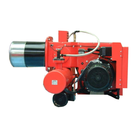
- Page 1 G100 Universal Oil Burner Installation & Maintenance Manual...
-
Page 2: Table Of Contents
Contents General information ........................3 Checking scope of supply and electrical ratings ................ 3 Operating instructions ........................ 3 Instruction ..........................3 Maintenance and customer service ................... 3 Technical specifications ......................4 Functional description ........................ 4 Air/oil flow schematic........................4 Installing flange and burner......................5 Connecting to power supply....................... -
Page 3: General Information
General information 1. General information An oil-fired system must be installed in compliance with a number of regulations and requirements. It is therefore the duty of the installer to be familiar with all applicable regulations and requirements. Installation, start-up and maintenance must be performed with utmost care. The burner must not be operated in rooms with high levels of air humidity (laundry rooms), dust or corrosive vapours. -
Page 4: Technical Specifications
Technical specifications 6. Technical specifications Burner type Technical specifications G100 Output, fuel oil 70 - 132 Output, rapeseed oil 65 - 101 Oil throughput kg/h Compressor output 11.5 Primary air connection 0.4 - 1.5 Motor output Heating element 1100 Voltage... -
Page 5: Installing Flange And Burner
Install flange and burner 9.Install flange and burner Attach the burner flange and the seal to the heat generator. 10. Connect to power supply 7-pin • Connect the burner to the power supply using the supplied connector unit as indicated in the wiring diagram. -
Page 6: Oil Pump
Oil pump 12. Oil pump The oil pumps serve as delivery units, pumping oil into the burner tank. The atomisation of the oil is not dependent on the oil pressure. Suntec oil pump: = feed = return = pressure pipe connection = pressure measuring connection = vacuum measuring connection = pressure adjustment... -
Page 7: Control Unit
Function testing the control unit 15. Function testing the control unit Carry out the following checks after start-up and after the burner has been serviced: • Restarting with a covered flame detector: the control unit must go into fault mode on expiration of the safety period. •... -
Page 8: Table Of Settings
If the oil level is too high, the float switch will switch off the burner. If the oil level is too low, the heating cartridge will become encrusted or damaged. Adjustment table for rapeseed oil Burner type G100 Output in kW Oil throughput in kg/h 10.1... -
Page 9: Settings For Primary Airflow
Settings for primary airflow 17. Settings for primary airflow The primary airflow should be set using the pressure regulator (1) according to the required burner output. The information given in the diagram can be used as guide values. Higher-viscosity fuels require higher air pressures. 18. -
Page 10: Flue Connection
Flue connection 19. Flue connection The prerequisite for perfect operation of the furnace is a correctly dimensioned flue. Dimensioning is effected in accordance with DIN 4705 in consideration of DIN 18160 and based on the boiler and burner outputs. For operation on a sliding basis, provide flues as per DIN 18160 part, group 1. The flue gas mass flow of the total rated heat output must be factored into the calculation. -
Page 11: Wiring Diagram
Circuit diagram 22. Circuit diagram Boiler controller Flame detector MZ770 = blue Heating coil 1100 W br = brown Ext. fuse ge = yellow Control thermostat gr = grey Ext. temperature control grü = green Ext. safety temperature limiter sw = black Safety thermostat (STB) = red Ext. -
Page 12: Possible Errors
Troubleshooting 23. Troubleshooting Observation Cause Remedy Open the water drain cock on the burner tank, Oil not combustible due to sludge and / or water drain off sludge and water or use a higher-grade heating oil Refill tank with oil Oil tank empty Oil level in burner tank too high Correct the oil level by draining off oil by means... -
Page 13: Exploded View Drawing / Parts List
Exploded view drawing / spare parts list 24. Exploded view drawing / spare parts list... - Page 14 Drain valve 47-90-10472 Intake tube compl. 47-90-24514 Heating coil 1100 W 47-90-24505 Oil tank G100 compl. 47-90-26177 Oil tank cover 47-90-24520 Oil tank - nozzle assembly connecting tube part 1 37-90-10370 Oil tank - nozzle assembly connecting tube part 2 37-90-10371 Control housing shroud, compl.
-
Page 16: Burner Dimensions / Boiler Connecting Dimensions
G100 Universal Oil Burner 07/11 Enertech Limited, P O Box 1, Vines Lane Droitwich, Worcestershire, WR9 8NA tel: +44 (0) 1905 794331 • fax:+44 (0) 1905 794017 email: info@nu-way.co.uk • web: www.nu-way.co.uk...
Need help?
Do you have a question about the G100 and is the answer not in the manual?
Questions and answers