Teltonika RUT104 User Manual
3g
Hide thumbs
Also See for RUT104:
- Quick start manual (2 pages) ,
- Quick start manual (2 pages) ,
- User manual (51 pages)
Table of Contents
Advertisement
Advertisement
Table of Contents

Related Manuals for Teltonika RUT104


Summary of Contents for Teltonika RUT104
-
Page 2: Legal Notice
TELTONIKA Ltd is prohibited. The manufacturer reserves the right to modify the product and manual for the purpose of technical improvement without prior notice. -
Page 3: Table Of Contents
SAFETY INFORMATION ........................5 PRODUCT OVERVIEW ..........................6 Introduction ............................. 6 Package contents ............................. 6 System requirements ..........................6 RUT104 Hardware, LED's and connections ..................7 2.4.1 Back panel ............................7 2.4.2 Front panel ............................ 7 GETTING STARTED ..........................8 Initial setup ............................... - Page 4 Appendix A Configuring PC wireless security ..................35 Appendix B Changing router IP address ....................37 Appendix D Accessing RUT from the WEB ..................38 Appendix E SIM card public or private IP address ................39 P a g e...
-
Page 5: Safety Information
1 SAFETY INFORMATION In this document you will be introduced how to use 3G Mobile Router safely. We suggest you to adhere to following recommendations to avoid any damage to person or property. You have to be familiar with the safety requirements before starting to use the device! 3G Mobile Router is used to provide a mobile Internet access using a GSM network. -
Page 6: Product Overview
2 PRODUCT OVERVIEW 2.1 Introduction Teltonika 3G Mobile Router provides WAN connectivity to wired and wireless clients using the 3G cellular data network. It allows multiple users to get IEEE 802.11 compliant connection within your wireless broadband network with a single 3G data access account and SIM card. 3G Mobile Router is extremely useful for mobile work teams or emergency crews that need access to the broadband Internet but have no permanent base. -
Page 7: Rut104 Hardware, Led's And Connections
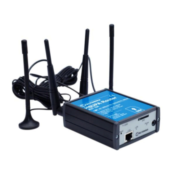
2.4 RUT104 Hardware, LED's and connections 2.4.1 Back panel Figure 1. Router back panel view. 1. Main GSM antenna connection. 2. Wireless LAN antenna connection. 3. Aux GSM antenna connection. 4. Wireless LAN antenna connection. 2.4.2 Front panel Figure 2. Router front panel view. -
Page 8: Getting Started
3 GETTING STARTED 3.1 Initial setup 3G Mobile Router enables to access network using a wireless connection from virtually anywhere within the operating range of wireless network. Some things should be considered before finding place to set up access point: 1. -
Page 9: Router Configuration
4 ROUTER CONFIGURATION 4.1 Connect to router WEB configuration page using wired connection Step 1 Connect 3G Mobile Router to your PC using LAN cable. Step 2 Setup Local Area Network adapter on your computer (Go to Start > Settings > Network Connections Right click on Local Network Connection select Properties) Step 3 Setup the Local Area network adapter’s IP address. -
Page 10: Connect To Router Web Configuration Page Using Wireless Connection
Right click on Wireless Network Connection and chose Enable. Step 4 Choose the wireless network (default: www.teltonika.lt) from the list of available wireless networks. Step 5 Open the Web browser and type the device IP address (default 192.168.0.1) and enter the 3G Mobile Router administrator login details to access the Web management. -
Page 11: Web Configuration Page Interface Structure
4.3 WEB configuration page interface structure The main Web management menu is displayed after successful login into the system (Figure 3). From this menu all essential configuration pages are accessed. Figure 3. Main Management Menu By default the Quick Setup menu is activated. The web management menu has the following structure: Quick Setup –... -
Page 12: Quick Setup
4.4 Quick Setup Use Quick Setup to quickly configure basic 3G Mobile Router settings. The configuration is made in four steps (this is the default page when accessing the administration web management interface). To start quick setup wizard click button QUICK SETUP. Step 1. -
Page 13: Status
Step 4. After successful configuration please click button and then click the button. The router will reboot and start up with new settings. The process will take several minutes. 4.5 Status 4.5.1 System Information System Information menu displays general devices status. Figure 4. -
Page 14: Hardware Information
4.5.2 Hardware information Figure 5. Hardware information Uptime – displays the time since the system was last rebooted. Firmware version – displays current version of the firmware. Average system load – displays the average load of the device processor in the period of the last 1 minute, 5 minutes and 15 minutes (a larger value means a larger average load on the processor: <1.0 –... -
Page 15: Configuration
4.6 Configuration 4.6.1 Mobile Network Settings To set up the GSM connection SIM card is required. SIM card is not supplied with the router. It may be purchased from internet service provider. The following information to connect to the internet is required: 1. -
Page 16: Network Settings
4.6.2 Network Settings This section will allow you to change the local network settings of the router and to configure the DHCP settings Figure 9. Network settings. Router IP address. The IP address of the router. The default IP address is 192.168.0.1. Subnet mask. -
Page 17: Wireless Settings
4.6.3 Wireless Settings 4.6.3.1 Hardware wireless settings Figure 11. Wireless network settings. Enable radio. Check the box to enable the wireless function. If you do not want to use wireless network, uncheck the box to disable the wireless function. IEEE mode. Specify the wireless network mode [B, G, mixed B/G, G Dynamic Turbo]. Channel. -
Page 18: Dynamic Dns Settings
Encryption. Choose the authentication method for wireless network: No Encryption. It will let anyone within range and with the proper equipment to connect onto your network within the router operating range. WEP Open System – choose the 64 bit WEP security with one of four pre-shared keys. WEP Shared Key–... -
Page 19: Services
4.6.5 Services In this section HTTP, SSH services which are important for remote control monitoring and management may be enabled and disabled. 4.6.5.1 Figure 14. SSH service configuration Enable SSH. Check the box to enable SSH service. Port. Set port value of the SSH service. Enable access form WAN. -
Page 20: Vpn
4.7 VPN 4.7.1 OpenVPN (site to site ) OpenVPN site to site graphical user interface (GUI) implementation allows connecting two remote networks via point-to-point encrypted tunnel. OpenVPN implementation offers a cost-effective simply configurable alternative to other VPN technologies. The OpenVPN security model is based on SSL, the industry standard for secure communications via the internet. -
Page 21: Server Configuration
4.7.1.1 Server configuration Figure 18. Server configuration Enable. Check box to enable the OpenVPN. Tun/Tap. Select tunneled or bridged connection. Protocol. Select UDP or TCP protocol. Port. Set the OpenVPN port. Default port 1194. LZO. Check box to enable the LZO compression. Default: disabled. Debug level. -
Page 22: Client Configuration
4.7.1.2 Client configuration Figure 19. Client configuration Enable. Check box to enable the OpenVPN. Tun/Tap. Select tunneled or bridged connection. Protocol. Select UDP or TCP protocol. Port. Set the OpenVPN port. Default port 1194. LZO. Check box to enable the LZO compression. Default: disabled. Debug level. -
Page 23: Gre Tunnel
4.7.2 GRE Tunnel GRE (Generic Routing Encapsulation RFC2784) is a solution for tunneling RFC1812 private address-space traffic over an intermediate TCP/IP network such as the Internet. GRE tunneling does not use encryption it simply encapsulates data and sends it over the WAN. WAN IP: WAN IP: A.A.A.A... -
Page 24: Ipsec
4.7.3 IPsec The IPsec protocol client enables the router to establish a secure connection to an IPsec peer via the Internet. IPsec is supported in two modes - transport and tunnel. Transport mode creates secure point to point channel between two hosts. Tunnel mode can be used to build a secure connection between two remote LANs serving as a VPN solution. -
Page 25: Automatic Ipsec Key Exchange
4.7.3.2 Automatic IPSec Key exchange Figure 23. Authentication header settings Enable IPSec. Check box to enable IPSec IPSec key exchange mode. Select the Manual or Automatic Key exchange. Enable NAT traversal. Enable this function if client-to-client applications will be used. Peers identifier type. -
Page 26: Admin
4.8 Admin Use the Admin menu to define access settings to the device, or to use the following system utilities: Account – change administrator’s password. NTP – Manage system time and date. Firmware upgrade – new firmware upgrade. ... -
Page 27: Firmware Upgrade
Offset frequency. Frequency adjustment for the local clock. Delete – click to remove selected NTP servers from the device system. Add – click Add button to add time server. The new field with server will appear. 4.8.3 Firmware upgrade To update your device firmware use the Firmware upgrade section, select the firmware file and click the Firmware upgrade button: Figure 26. - Page 28 Description. Describe the rule for your convenience. Note: After pressing Save button wait for confirmation before executing next command. Example 1: Block all incoming connection requests Example 2: Allow incoming telnet (port 23) requests from host 84.12.145.17 to IP address 192.168.0.10.
- Page 29 29 | P a g e...
-
Page 30: Port Forwarding
4.9.1 Port forwarding This section will let to manage port forwarding. Figure 28. Port forwarding settings. Application name. Set the name of the application. Input port range. Set incoming port value or range. Protocol. Select TCP, UDP, or BOTH Destination IP address Enter the IP address of the computer on your local network that you want to allow the incoming service to be forwarded. -
Page 31: Tools
Figure 30. DMZ settings Enable - Click to enable or disable the DMZ. Destination IP address - Type a host IP address for the DMZ. All remaining incoming packets will be sent to this IP address. 4.10 Tools 4.10.1 Site Survey The Site Survey test shows overview information for wireless networks in a local geographic area. -
Page 32: Diagnostics
Ping interval – specify the monitoring time period in seconds Time scale – set ping interval time scale in minutes or hours Retry count – specify the number of failed reach ability checks Enable reboot if no echo received– enable reboot the router if no echo to sent ICMP requests is received. -
Page 33: Technical Specification
Detachable reverse SMA Management User-friendly Web GUI Wired and wireless network status Site survey test Traffic monitoring Firmware upgradeable IPsec pass through, GRE Tunnel pass through GRE tunnel, IPsec client RUT104 Quad Band (850/900/1900/2100 MHz) 33 | P a g e... - Page 34 GSM/EDGE/GPRS/HSUPA/HSDPA/UMTS RUT104 Power Class: Power Class 4 (2 W, 33 dBm) for GSM/GPRS 850/900 MHz bands Power Class 1 (1 W, 30 dBm) for GSM/GPRS 1800/1900 Mhz bands Power Class E2 (0.5 W, 27 dBm) for EDGE 850/900 MHz bands Power Class E2 (0.4 W, 26 dBm) for EDGE 1800/1900 MHz bands...
-
Page 35: Appendix A Configuring Pc Wireless Security
6 Appendix A Configuring PC wireless security 1. Click Start => Settings => Control Panel (The Control Panel should be in Classic view). Double click on the Network Connections icon. 2. Right click on the Local Area Connection for wired or Wireless Network Connection for wireless connection and select Properties. - Page 36 7. Click Refresh network list 8. Choose the network with SSID witch was configured on the router (default www.teletonika.lt) and click connect. The window asking for the key should appear. The Network key is the passphrase which was typed in the router settings. 36 | P a g e...
-
Page 37: Appendix B Changing Router Ip Address
7 Appendix B Changing router IP address Step 1 Connect to router WEB configuration page. Then go CONFIGURATION then Maintenance. Step 2 Change router IP address: In the field Router IP address write new router address. (eg. 192.168.123.1) Step 2 Change router DHCP server assigned IP address range: Type the fields IP address from and IP address to type new range Example: Router IP address:... -
Page 38: Appendix D Accessing Rut From The Web
8 Appendix D Accessing RUT from the WEB There are two ways to connect the router from internet: 1. Using SIM card with public static IP address 2. Using SIM card with public dynamic IP address witch will be linked to static hostname using DDNS service. -
Page 39: Appendix E Sim Card Public Or Private Ip Address
9 Appendix E SIM card public or private IP address Step 1 Connect PC to router and check if it is possible to browse Internet. If you are not able then there is problem with MOBILE NETWORK SETTINGS. If you are able then go to next step.
Need help?
Do you have a question about the RUT104 and is the answer not in the manual?
Questions and answers
Will my 104 router still work when g3 is shut down
The Teltonika RUT104 router relies on a 3G cellular data network for WAN connectivity. If 3G networks are shut down, the router will no longer be able to connect to the internet via cellular data. However, it may still function as a local network device for wired and wireless connections if alternative internet access is available.
This answer is automatically generated