Table of Contents
Advertisement
Advertisement
Table of Contents

Related Manuals for Kranzle 11/130


Summary of Contents for Kranzle 11/130
- Page 1 Hot Water-High Pressure Cleaners 11/130 12/150 15/120...
-
Page 2: Dear Customer
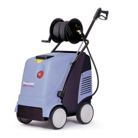
- containers - flagstones - sheds e.g.: food processing - removing of old paint etc. - machines industry therm CA 11/130 therm CA 12/150 therm CA 15/120 Technical data 30 - 130 bar 30 - 150 bar 30 - 120 bar... - Page 3 Description Connections and functional parts Water inlet connection with filter Storage bin for spray gun and pipe Power cable Brake Winder for cable 10 Fuel tank Suction hose for detergent 11 Filler aperture for fuel High pressure hose 12 High pressure outlet Spray gun 13 Hose drum (special accessories) Spray pipe attachment...
-
Page 4: Water System
Description Water system The water flows into a tank. A float valve (a) regulates the water intake. The water is then directed to the safety spray pipe under pressure from the high pressure pump. The high pressure spray is formed through the nozzle on the spray pipe. - Page 5 Description Spray pipe with spray gun The spray gun only allows the machine to be operated when the safety trigger is pulled. The spray gun can be used when the safety trigger is pulled. The machine is started and the liquid transported to the nozzle. Spray pressure builds up and quickly reaches the selected operating pressure.
-
Page 6: Heat Exchanger
Description Heat exchanger Heating coil: 34 m long - Content: 5 l of water – Heating capacity: 70 k W The heat exchanger is heated by a high pressure fan heater. A ventilator (1) draws in the cold, fresh air from the bottom end of the machine and forces it upwards between the outer mantle (2) and the inner mantle (3). -
Page 7: Safety Information
Safety Information Brake The Kränzle therm is fitted with a brake that prevents the machine from rolling away on flat ground. Always apply the brakes firmly when working with the machine !!! Brake applied Brake not applied If you want to move the Now you can high pressure cleaner move the cleaner... - Page 8 Safety Information Safety Information Important !!! The machine must be disconnected from the power supply when servicing work is being carried out. The master switch should be in position "0" and the plug out of the socket. Do not use the cleaner if electrical connections or other safety-relevant parts (e.g.
- Page 9 Safety Information The machine may not be set up and used in rooms where there is a danger of fire or explosion. The machine may not be used under water. Air is required for combustion, and exhaust fumes are generated. If the machine is used in closed rooms, make sure that the exhaust fumes can escape and that there is adequate ventilation.
- Page 10 This is prohibited! Never direct the water jet at people or animals! Do not damage the power cable or repair it incorrectly! Never pull the high pressure hose if it has formed kinks or “nooses”! Never pull the hose over sharp edges!
- Page 11 This is prohibited! Never allow children to use the high pressure cleaner! Never direct the water jet at the machine itself! Never direct the water jet at a power socket!
-
Page 12: Electrical Connection
Commissioning Commissioning Secure the machine by applying the brake (see page 8) and check the oil level of the high pressure pump. Do not start the machine if there is no oil on the dipstick. Fill oil if necessary. See page 18. Fill the fuel tank with light heating oil prior to use. -
Page 13: High Pressure Connection
Commissioning High pressure connection Connect the high pressure hose to the handgun. Unwind the hose so that it is free of loops and connect it to the handgun and the machine. Check that all screw-type connections are pressure-tight. Leaks from gun, high pressure hose or hose drum must be eliminated immediately. -
Page 14: Adjusting The Pressure
Commissioning Commissioning - Switch off the ignition. Rocker switch (16) to „0“. - Set the pressure control (4) valve to maximum pressure (see below) and close the detergent valve (20). - Open the gun and switch the master switch (15) on. The high pressure pump now presses the air out of the lines, and after a short time the high pressure spray is formed and the operating pressure is reached. -
Page 15: Usage As A Cold Water High Pressure Cleaner
Commissioning Usage as a cold water high pressure cleaner - Leave the ignition "OFF". Rocker switch (1A) to „0“. - Start cleaning Usage as a hot water high pressure cleaner - Set the target temperature on the thermostat to min. 40 °C and than switch the ignition "ON"... -
Page 16: Anti-Freeze Protection
Decommissioning Decommissioning - Switch off the master switch (position "0"). - Pull the plug out of the power socket. - Turn off the water supply. - Open the gun until the pressure is gone. - Lock the gun. - Disconnect the water hose. - Slacken the connections of the high pressure hose and gun and unscrew the high pressure hose from the machine (appliances without hose drum). -
Page 17: Care And Maintenance
Care and Maintenance Care and Maintenance Care and maintenance is required to keep the machine in good working order, and to allow you to enjoy the machine for as long as possible. IMPORTANT!!! Always remove the plug before working on the machine! Only use original Kränzle spare parts What to do! - Weekly, or after approx. -
Page 18: Oil Leakage
Care and Maintenance Oil leakage If oil leaks out, go to the nearest customer service (dealer) immediately. (Environmental damages, transmission damages, loss of guarantee.) Type of oil: Formula RS of Castrol - Quantity: 1.0 l Adjusting ignition electrodes For a smooth ignition, the setting of the ignition electrode must be controlled regularly. -
Page 19: Decalcifying The Heating Coil
Care and Maintenance Decalcifying the heating coil Calcified machines use an unnecessary amount of energy because the water can only be heated slowly and the excess pressure valve feeds a part of the water back into the pump circuit. Calcified machines can be recognised by increased pipeline resistance. Check pipeline resistance by disconnecting the high pressure lance from the gun and switching the machine on. - Page 20 Care and Maintenance Rules, directives, inspections Inspections performed by Kränzle - measurement of earth line resistance - measurement of voltage and current - inspection of tension consistency with +/- 1530 V - pressure check of heating coil at 300 bar - visual and functional check as per the inspection sheet provided - exhaust fume analysis (see test strips provided) Guidelines for liquid sprayers...
- Page 21 Description of function -Troubleshooting IMPORTANT!!! Always remove the plug before working on the machine! Master switch Ignition “ON/OFF Brief operating instructions Thermostat 5 Hand wheel for pressure adjustment 14 Fuel manometer 6 High pressure pump 15 Fuel filter 7 Pressure switch black (start solenoid 16 Ignition transformer valve) 17 Thermosensor water...
- Page 22 Description of function -Troubleshooting Cold water mode 1. Connect to water supply and determine whether the water tank fills up completely and the float valve stops. 2. Ignition (2) to OFF. 3. Main switch (1) to ON. 4. Open high pressure gun. The apliance started, the pump sucks water from the water tank and moves the water through the heating coil to the lance, the pressure is increased.
- Page 23 Description of function -Troubleshooting The thermostat (4) is controlled via a thermo-sensor (18) mounted at the outlet of the heaiting coil. In the switchbox (below the operating panel), a fuse (F1) is installed on the board protecting the motor (11) of the fuel pump and the ventilator. If the motor is overloaded the fuse trips.
-
Page 24: Troubleshooting
Troubleshooting IMPORTANT!!! Always remove the plug before working on the machine! Malfunction Cause of malfunction / Trouble shooting W ater supply Water tank runs over. Float valve is dirty. Float valve is defect. Water tank does not fill completely. Float valve is defect Water filter soiled. - Page 25 Troubleshooting Malfunction Ca use of malfunction / Trouble shooting Machine does not switch off Ch eck return body and O-ring in unloader of the valve housing. Ch eck pressure switch (red). Test: Jumper (red) pressure switch Ch eck micro switch. Ch eck cable connections.
- Page 26 Troubleshooting Malfunction Cause of malfunction / Trouble shoooting Solenoid valve on the fuel pump Check pressure switch (black). does not open Solenoid valve is defect or dirty. Test: Pressure switch (black) Bridge in terminal box between terminal 3 +4 Clean filter, clean supply line, clean fuel pump. Setting is wrong.
-
Page 27: Pipeline Plan
Pipeline plan High pressure connection Water inlet Safety valve, number 5 must be set approx. 15 % higher than the unloader valve on the HP pump 1 Float valve, water inlet Pressure switch Burner release 2 Water tank 7 Safety valve for heating coile 3 Control valve, detergent 8 Flow controller 4 High pressure pump... - Page 28 Master switch Switch Heating Ord.-No: 44.952 Excess current actuator 15 A Interf. suppr. for ignition transformer A.C. motor installed on board High pressure pump Connection via grounding plug 230 V / 50 Hz Burner Ignition motor transformer Fuel valve Sensor line F1 F2 Thermostat Flow controller...
- Page 29 Master switch Switch Heating Ord.-No: 44.952 Excess current actuator 8,5 A Interf. suppr. for ignition transformer Three-Phase motor installed on board High pressure pump Connection via CEE 4x 16 A 380 V 50 Hz +MP Burner Ignition motor transformer Fuel valve Sensor line F1 F2...
-
Page 30: Complete Assembly
Complete Assembly... - Page 31 Sc hraube M 8 x 110 DIN931 44.826 Brennstofftank sc hwarz 44.806 1 Sc heibe D40x19x1,5 46.533 Haube hinten 44.812 36.1 Motor-Pumpe für therm CA 11/130 44.960 Sc hraube M5x14 DIN7985 40.536 36.2 Motor-Pumpe für therm CA 12/150 44.961 Haube vorn 44.813 36.3...
-
Page 32: Electronics Switchbox
Electronics switchbox... - Page 33 Qty. Order No. Elektrokasten 44.807 1 Sc hraube 3,5 x 14 44.525 Deckel für Elek trokasten therm CA 11/130 1 44.808 6 Netzanschlußleitung Drehstrom 44.036 Deckel für Elek trokasten therm CA 12/150 1 44.808 7 8,0m, 4x 1,5 mm², H07RNF Deckel für Elek trokasten therm CA 15/120 1...
- Page 34 Water supply and brake Description Qty. Order No. Wassertank 44.805 1 Schwimmerventil 46.250 Moosgummidichtung 46.261 Mutter R3/4“ 46.258 Kunststoffschraube 5x14 43.426 Scheibe 5,3 DIN9021 50.152 Zugfeder 46.020 Deckel Bremse 46.016 Hebel Bremse 44.804 Zylinderschraube M 8 x 20 41.480 Innensechskantschraube M4x10 46.002 Schelle 43.431...
-
Page 35: Fuel Supply
Fuel supply Description Qty. Order No. Deckel Brennstoffversorgung 44.011 Flansch mit Brennstoffleitungen 44.842 Gummidichtung 44.012 PA-Schlauch DN6 0,4 m 44.403 PA-Schlauch DN6 0,3 m 44.403 PA-Schlauch DN6 0,4 m 44.403 Steckverbinder 6 - 6 44.404 Schraube 5,0 x 25 41.414 1 Steckverbinderstutzen 1/8“... -
Page 36: Combustion Chamber
Combustion chamber... - Page 37 Kränzle therm CA Spare parts list KRÄNZLE therm CA Combustion chamber Description Qty. Order No. Gebläsegehäuse 44.802 Schraube M 5 x 10 43.021 Schraube 3,9 x 9,5 41.079 F ederring A 8 44.222 Edelstahlmutter M 8 14.127 2 T iefenanschlag 44.088 Brennstoffleitung „Düsenstock“...
- Page 38 Combustion chamber...
- Page 39 44.079 Innendeckel mit Kamin und Flammrohr 44.861 Außendeckel 44.862 Brennstoffdüs e 60° B 1,35 gph 44.077 2 (CA 11/130; CA 12/150) Brennstoffdüs e 60° B 1,5 gph 44.077 (CA 15/120) Blockelek trode 44.854 Düsenstock Ø 25 mm, 6 Schl. 44.076 4 Düsenhalter...
-
Page 40: Unloader And Pressure Switch
Unloader and pressure switch Description Qty. Order No. Guide piston compl. 40.490 Output piece for red switch, compl. 15.009 3 Pressure switch (red) compl. with cable 0,49 m 44.120 1 Ventilgehäuse kpl. 44.320 Pressure switch (black) compl. with cable 0,59 m 44.120 Output piece for black switch, comp. - Page 41 Kränzle therm CA Spare parts list KRÄNZLE therm CA Unloader and pressure switch Description Qty. Order No. O-Ring 16 x 2 13.150 O-Ring 13,94 x 2,62 42.167 O-Ring 12.256 Edelstahlsitz 14.118 Sicherungsring 13.147 Edelstahlkugel 8,5 mm 13.148 Edelstahlfeder 14.119 Verschlussschraube 14.113 Steuerk olben 14.134...
-
Page 42: Heating Coil
Safety valve for heating coil Safety valve for heating coil (Adjustment must be approx. 15% above the operating pressure) Description Qty. Order No. Ventilkörper 14.145 Ermetoverschraubung R 3/8" x 12 mm 40.076 Ermetowinkel 12 mm x 12 mm Mutter 44.865 Stopfen R1/4"... - Page 43 Plunger 18mm (AM-Pumpe) 40.455 Sprengring 41.035 Wellenscheibe 40.043 Axial-Rollenkäfig 40.040 AS-Scheibe 40.041 11.1 Taumelscheibe 9,0° (therm CA 11/130) 40.473-9,0 11.2 Taumelscheibe 9,85° (therm CA 12/150) 40.473-9,85 11.3 Taumelscheibe 12,25° (therm CA 15/120) 40.473-12,25 Schraube DIN912 M 8 x 30 41.036 3 Ölschauglas 42.018 1...
-
Page 44: Valve Housing
Valve housing... - Page 45 Kränzle therm CA Spare parts list KRÄNZLE therm CA Valve housing AM for plunger diameter 18 mm Description Qty. Ord.-No Ventilgehäuse AM-Pumpe 40.451 O-Ring 15 x 2 41.716 Ventile (grün) für APG-Pumpe 41.715 1 O-Ring 16 x 2 13.150 Ventilstopfen 41.714 Ventilstopfen mit R1/4"...
-
Page 46: Pump Motor
Pump motor Description Qty. Order No. Motorgehäuse mit Stator Wechselstrom 43.826 Motorgehäuse mit Stator Drehstrom 43.827 Rotor mit Motorwelle 43.316 Passfeder 6 x 6 x 20 41.483 1 Motor-Lager B-Seite 6205 - 2Z 43.317 Motor-Lager Kegelrollenlager 31304 40.472 Toleranzhülse 43.330 1 Öldichtung 25 x 35 x 7 41.024 Lüfterrad BG 90... -
Page 47: Terminal Box
44.814 Deckel Klemmkasten 44.815 Dichtung Deckel 44.816 Schraube 5,0 x 14 43.426 Kunststoffschraube 3,5 x 20 43.415 Lüsterklemme 5-pol. 43.326 1 PG9-Verschraubung (CA 11/130) 43.034 PG9-Verschlusstopfen (CA12/150) 44.142 PG9-Gegenmutter 41.087 1 PG16-Verschraubung 41.419 1 PG16-Gegenmutter 44.119 Kondensator 70 µF 43.322 Flac hdichtung 43.030... -
Page 48: Hose Drum
Hose drum (Special accessory) Upgrade kit: 44.152 2... - Page 49 Spare parts list KRÄNZLE therm CA Hose drum Description Qty. Order No. Description Qty. Order No. Seitensc hale Schlauchführung 40.302 Haltebügel 44.143 Seitensc hale Wasserführung 40.301 Gummistopfen 40.208 1 Trommel Unterteil 40.304 Sc hlossschraube M 8 x 35 41.408 Trommel Oberteil 40.303 Elastic-Stop-Mutter M 8 41.410...
- Page 50 23.1 Flachstrahldüs e 25070 D25070 Rep.-Kit 12.158 Pos: 3, 4, 5, 8, 9, 12, 15, 16; 21 Griff komplett 12.164 Midi-gun with extension 12.164 1-25045 and HP-nozzle 25045 (CA 11/130; CA 12/150) Midi-gun with extension 12.164 1-25070 and HP-nozzle 25070 (CA 15/120)
-
Page 51: Ec Declaration Of Conformity
Art. 13, High-pressure water jet machines Appendix 3, part B, chapter 27 Sound power level measured: CA 11/130: 88 dB (A); CA 12/150: 90 dB (A); CA 15/120: 90 dB (A); guaranteed: CA 11/130: 90 dB (A); CA 12/150: 92 dB (A);... -
Page 52: Inspection Sheet
Inspection sheet Customer ..........All lines connected Hose clamps tight Screws all installed and tightened Ignition cable plugged in Visual check carried out Brake function checked Leak test Water tank filled and checked Water inlet checked for tightness Float valve function checked Machine checked for tightness under pressure Electrical check Earth line checked... - Page 53 Kränzle therm CA ________ Result of flue gas analysis Steam phase checked Chemical valve checked Start/Stop automatic and re-run delay checked Fuel shortage switch checked Thermostat function checked Burner function checked Water inlet temperature 8 9 10 13 14 15 °C Water temperature reached °C...
-
Page 54: Inspection Report For Hp Cleaners
Inspection report for HP cleaners Inspection report on annually carried out Labour Safety Inspection (UVV) according to the Guidelines for Liquid Spray Equipment. (This inspection sheet serves as proof for the completion of the retest and must be kept carefully!) Owner: _____________________ Type: therm CA ____ Built: ________ Address:... - Page 55 Inspection report for HP cleaners Inspection report on annually carried out Labour Safety Inspection (UVV) according to the Guidelines for Liquid Spray Equipment. (This inspection sheet serves as proof for the completion of the retest and must be kept carefully!) Owner: _____________________ Type: therm CA ____ Built: ________ Address:...
- Page 56 Reprint only allowed with the authorization of As date of 15. 04. 2009...
Need help?
Do you have a question about the 11/130 and is the answer not in the manual?
Questions and answers