
Related Manuals for SII RP-D10 Series


Summary of Contents for SII RP-D10 Series
- Page 1 USER'S GUIDE Thermal Printer RP-D10 SERIES Read this USER'S GUIDE carefully before using the printer. Keep this USER'S GUIDE in a place where it can be accessed quickly.
- Page 2 Copyright 2013 by Seiko Instruments Inc. All rights reserved. The information contained herein is the property of SII and shall not be reproduced in whole or in part without prior written approval of SII. SII reserves the right to make changes in the specifications and materials contained herein without notice and shall not be responsible for any damages (including consequential) caused by reliance on the materials presented, including but not limited to typographical, arithmetic, and listing errors.
- Page 3 Federal Communications Commission (FCC) compliance statement This equipment has been tested and found to comply with the limits for a Class A digital device, pursuant to part 15 of the FCC Rules. These limits are designed to provide reasonable protection against harmful interference when the equipment is operated in a commercial environment.
-
Page 4: Table Of Contents
1. INTRODUCTION This manual describes how to handle RP-D10 thermal printer (hereinafter referred to as printer), specified AC adapter, specified AC cable, and other accessories. Read through the "2. SAFETY PRECAUTIONS" and "3. OPERATING PRECAUTIONS" carefully before using the printer, and handle it safely and properly. Keep this manual in a place where it can be accessed quickly. -
Page 5: Safety Precautions
2. SAFETY PRECAUTIONS In this SAFETY PRECAUTIONS, the following symbols are used to ensure safe and proper use of products and prevent from damaging devices. Failure to follow the instructions marked with this symbol could WARNING result in severe personal injury or death. Failure to follow the instructions marked with this symbol could CAUTION result in minor personal injury or property damage. - Page 6 OPERATING PRECAUTIONS WARNING Never attempt the followings. Failure to follow the instructions leads to fire, electric shock, or accident. Do not insert any foreign objects such as a piece of metal or any liquid into the products. Do not touch the metal parts of the terminal, AC plug, and DC plug. To avoid short circuits, prevent terminals of the products, AC plug, and DC plug from touching any conductor such as metal.
- Page 7 Procedures to take when in trouble Follow the instructions in the cases below. Failure to follow the instructions may lead to fire, electric shock, or accident. Turn the power off and unplug the AC plug from an outlet in any of the cases below: ◆...
-
Page 8: Operating Precautions
3. OPERATING PRECAUTIONS Follow the precautions below to use the printer properly in order to deliver and maintain the full performance of the printer. Using the Printer ◆ Be careful not to drop or bump the printer on a hard surface. ◆... -
Page 9: Precautions On Discarding
◆ DO NOT drop or insert any foreign objects such as a clip, a pin, or a screw in the internal parts or slot of the printer. ◆ DO NOT drop any liquid or spray a solvent to the printer. ◆... - Page 10 Notations The following two types of notations are used throughout this manual to denote operating precautions and items to remember: NOTE ◆ Operating Precautions This box contains items that, when not followed, may lead to a malfunction or to a deterioration of performance. HINT •...
-
Page 11: Preparation
4. PREPARATION When you open the carton, make sure it contains the printer and its accessories. Sample thermal paper SAFETY PRECAUTIONS (one sheet) Partition plate R Printer USER'S GUIDE/ Various Software (CD-ROM, one piece) Partition plate L... - Page 12 Models including the AC adapter, AC cable, and interface cable are also available. Keep the package and packing materials for future transportation or long-term storage. The available accessories are shown below. See "5. IDENTIFYING THE MODEL TYPE" for the models which include accessories. Specified AC cable (the figure shows CB-US03-20A) Specified AC adapter...
-
Page 13: Identifying The Model Type
When the printer is incorporated into your equipment and then supplied electric power from the equipment, follow the rated value of input voltage for RP-D10 described in the specifications of "17. SPECIFICATION", and "2.3 POWER SUPPLY SPECIFICATIONS" in "RP-D10 SERIES THERMAL PRINTER TECHNICAL REFERENCE". -
Page 14: Each Part Of Printer
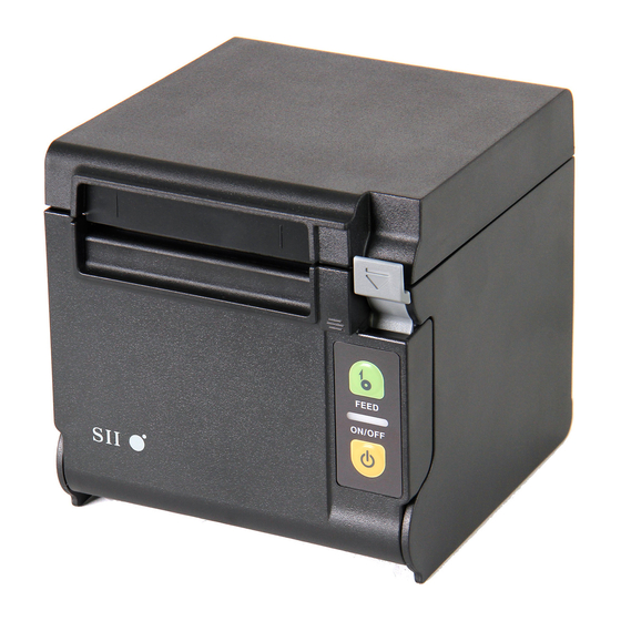
6. EACH PART OF PRINTER USB model Serial model USB + Serial model Ethernet model... - Page 15 1 POWER Switch 8 Thermal head The POWER Switch turns the printer on or off. The The thermal head prints data on the thermal paper. LED lights when turning the power on. To turn the NEVER touch the thermal head immediately after power off, hold down the switch for longer than three printing because it gets hot.
-
Page 16: Led Display
LED Display LED Indication LED (Color) (Lighting Pattern) Power off Power on (print-ready) Green Printing Green Output buffer full Green Blink-1 Out-of-paper error Orange Blink-2 Cover open error Orange Blink-1 Hardware error Head temperature error Blink-1 Vp voltage error Blink-2 Cutter error Blink-3... -
Page 17: Power Connection
7. POWER CONNECTION This printer can be powered with an AC adapter. Be sure to see "17. SPECIFICATION" for the AC adapter. Connecting the AC Adapter (1) Connect the AC cable to the AC adapter. (2) Insert the DC plug of the AC adapter to the power connector of the printer. (3) Insert the AC plug of the AC cable to an outlet. -
Page 18: Thermal Paper Setting
8. THERMAL PAPER SETTING The printer uses the paper roll (hereinafter referred to as thermal paper). The Function Setting of the printer differs depending on the used thermal paper. See "11. FUNCTION SETTING" for details. Thermal Paper Setting (1) Operate the release lever to the direction of the arrow shown in the figure to open the paper cover. ... - Page 19 (2) Take the glued end from the thermal paper. (3) Set the thermal paper from directly above to the paper holder. At the time, set the thermal paper direction as shown in the figure. Top eject Printing side Front eject Printing side...
- Page 20 (4) Pull the thermal paper straight. Make sure that the thermal paper does not slant. Top eject No good Good Front eject No good Good...
- Page 21 (5) Push firmly the part indicated by the arrow in the figure below to close the paper cover to avoid one side lock defect. Top eject Front eject NOTE ◆ Pull the thermal paper straight. ◆ Push the paper cover firmly to close and avoid one side lock defect. (6) After closing the paper cover, paper feed and paper cutting are performed automatically.
- Page 22 Thermal Paper Shape Good No Good No Good NOTE ◆ DO NOT use deformed thermal paper. Doing so may damage the printer. Good No Good NOTE ◆ In case of using loosened thermal paper, rewind it before using.
-
Page 23: Prevention And Treatment Of Paper Jam
9. PREVENTION AND TREATMENT OF PAPER JAM Do not touch the thermal paper when ejecting or before paper cutting. Covering the paper outlet or pulling out the thermal paper when ejecting may cause a paper jam, a cut failure, or line feed failure. Never open the paper cover during paper cutting. - Page 24 Cutter Error Treatment When the motor is locked during paper cutting due to a cutter error and the paper cover does not open, recover the printer according to the following procedures. (1) Turn the power off. NOTE ◆ Be sure to turn the power off before handling a cutter error. (2) Operate the release lever repeatedly to the end while holding the paper cover to retract the cutter blade.
-
Page 25: Test Print
10. TEST PRINT The printer has a test print function. In test print, the Function Setting of the printer and character strings for testing are printed. (1) Make sure that the thermal paper is set in the printer and the power is turned off. When the thermal paper is not set, set the thermal paper as instructed in "8. -
Page 26: Function Setting
The Function Setting of the printer are stored in the FLASH memory. They are effective until rewriting them again. You can set these functions by using the Memory Switch (hereinafter referred to as MS) MS1 to 7, 13, 15 to 17, and 40. See "RP-D10 SERIES THERMAL PRINTER TECHNICAL REFERENCE" for details. -
Page 27: Connecting To The Host Device
The Function Setting of the printer differs depending on the communication method used. See "RP-D10 SERIES THERMAL PRINTER TECHNICAL REFERENCE" for detail. An interface cable is required separately for the serial, USB, or Ethernet communication. See "17. - Page 28 Interface Cable for Serial Communication Interface Cable for Ethernet Communication NOTE ◆ When connecting an interface cable to the interface connector, push it until it clicks. ◆ NEVER connect plugs of other cables including drawer kick cable or phone line to the interface connector.
-
Page 29: Connecting To The Drawer
Connecting to the Drawer (1) Turn the power off. (2) Connect the plug of drawer kick cable to the drawer kick connector on the back side of the printer. (3) Turn the power on. NOTE ◆ When connecting or disconnecting the drawer kick cable, hold the plug and never pull the cable. -
Page 30: Settings When Using 58Mm Paper Width
13. SETTINGS WHEN USING 58mm PAPER WIDTH (1) Turn the power off. (2) Operate the release lever to open the paper cover. (3) Put the attached partition plate R or partition plate L into the paper holder with slanting position as shown in the figure below. - Page 31 (5) Put the hook which is located on the upper side of the partition plate R or partition plate L on the hole of paper holder as shown in the figure below. Hook Hook (6) Push the partition plate R or partition plate L to the direction of the arrow shown in the figure below with placing them along the side surface of the paper holder, and then put the projection which is located at the bottom of the partition plate in the hole of the paper holder.
- Page 32 (7) Turn the printer over, and make sure that the projection of the partition plate R or partition plate L is fit properly into the hole of the paper holder (the arrow shown in the figure below). See "RP-D10 SERIES THERMAL PRINTER TECHNICAL REFERENCE" to set the MS4-4 (Paper Width Selection) to 58mm. NOTE ◆...
-
Page 33: Wall Mounting Kit (Wlk-B01-1)
14. WALL MOUNTING KIT (WLK-B01-1) (1) Preparation Make sure that the product and its accessories are contained. Printer attachment screw (four pieces) (Tapping screw 3×6) Wall hanging bracket Wall hanging bracket attachment screw Printer bracket (six pieces) (Wood screw 3.8×18) - Page 34 (2) Installation of Printer Bracket Firmly attach printer bracket with four printer attachment screws as shown in the figure below. The tightening torque should be 39.2cN•m (4kgf•cm). NOTE ◆ Turn the power off before the operation. Remove the AC cable of the AC adapter and the interface cable.
- Page 35 (4) Installation of the Printer Slide the printer into the wall hanging bracket from the top to the bottom to insert the printer bracket into the wall hanging bracket, as shown in the figure. NOTE ◆ Check the place and the material/structure of the wall, and then install the printer securely.
-
Page 36: Printer Maintenance
15. PRINTER MAINTENANCE The thermal head of the printer does not require user maintenance. When paper powder accumulates, clean the thermal head to maintain maximum print quality for an extended period of time. Cleaning Thermal Head/Platen/Rubber Feet (1) Turn the power off. (2) Unplug the AC plug of the AC adapter from an outlet. -
Page 37: Troubleshooting
16. TROUBLESHOOTING Check the following points before requesting for repair: The power does not turn on • Is specified AC adapter being used? • Are the AC cable and AC adapter connected correctly? • Is the AC adapter connected to the printer correctly? ... -
Page 38: Specification
17. SPECIFICATION Printer Specifications Item Specification Model RP-D10 Printing method Thermal printing Number of characters per line Paper width 80 mm: 24 dots × 12 dots 48 digits (42 digits 16 dots × 8 dots 72 digits (64 digits Paper width 58 mm: 24 dots ×... -
Page 39: Interface Specifications
Interface Specifications Serial interface specifications Item Specification Synchronization method Asynchronous Baud rate 9600, 19200, 38400, 115200 bps Data length 7 or 8 bits Parity None, Even, or Odd Flow control Hardware control, Xon/Xoff USB interface specifications Item Specification Version Ver 2.0 conformity Printer data transmission mode Bulk transfer (12 Mbps) - Page 40 Russia Ask your SII sales representative when you want to operate the products in other countries than listed above. The compliant AC cable differs from country to country. See the Specified AC Cable Table below. Specified AC Cable Table...
-
Page 41: Accessories And Consumable Parts
18. ACCESSORIES AND CONSUMABLE PARTS Accessories Name Model Specified AC adapter PW-E2427-W1 Specified AC cable For Japan CB-JP03-20A For USA, Canada, Mexico CB-US03-20A For EU (except United Kingdom), EFTA, Russia CB-CE03-20A For United Kingdom CB-UK02-20A Wall mounting kit WLK-B01-1 Specified USB cable IFC-U02-1 Specified Serial cable... - Page 42 Seiko Instruments Inc. 1-8, Nakase, Mihama-ku, Chiba-shi, Chiba 261-8507, Japan Print System Division Telephone:+81-43-211-1106 Facsimile:+81-43-211-8037 Seiko Instruments USA Inc. Thermal Printer Div. 21221 S. Western Avenue, Suite 250, Torrance, CA 90501, USA Telephone:+1-310-517-7778 Facsimile:+1-310-517-7779 Seiko Instruments GmbH Siemensstrasse 9, D-63263 Neu-lsenburg, Germany Telephone:+49-6102-297-0 Facsimile:+49-6102-297-222 Seiko Instruments (H.K.) Ltd.
Need help?
Do you have a question about the RP-D10 Series and is the answer not in the manual?
Questions and answers