Table of Contents
Advertisement
Quick Links
Advertisement
Table of Contents

Related Manuals for SII DPU-S245


Summary of Contents for SII DPU-S245
- Page 1 DPU-S245 SERIES THERMAL PRINTER TECHNICAL REFERENCE U00117152801...
- Page 2 Copyright © 2009, 2010 by Seiko Instruments Inc. All rights reserved. Seiko Instruments Inc. (hereinafter referred to as “SII”) has prepared this technical reference for use by SII personnel, licensees, and customers. The information contained herein is the property of SII and shall not be reproduced in whole or in part without the prior written approval of SII.
- Page 3 PREFACE This technical reference describes the DPU-S245 series thermal printer. (hereinafter referred to as “printer”) Read the User’s Guide supplied with the printer for details regarding basic operation and maintenance procedures. DPU-S245 series have the following models. ・DPU-S245-00A-E (Standard model) ・DPU-S245-01A-E...
- Page 4 【Manual Configuration】 CHAPTER 1: TERMS USED IN THIS MANUAL ・ This chapter describes the basic terms that are frequently used in this technical reference. CHAPTER 2: SPECIFICATIONS ・ This chapter describes the printer main body and thermal paper specifications. CHAPTER 3: INTERFACE ・...
-
Page 5: Table Of Contents
TABLE OF CONTENTS Section Page CHAPTER 1 TERMS USED IN THIS MANUAL CHAPTER 2 SPECIFICATIONS PRINTER SPECIFICATIONS..................... 2-1 SPECIFIED THERMAL PAPER SPECIFICATIONS............2-3 2.2.1 Dimensions of Timing Mark Position................2-4 SPECIFIED BATTERY PACK SPECIFICATIONS ............. 2-6 PRECAUTIONS FOR USE....................2-7 CHAPTER 3 INTERFACE SERIAL INTERFACE SPECIFICATIONS (RS-232C CONFORMITY) ...... - Page 6 COMMAND DESCRIPTION ..................... 6-18 6.5.1 Command Format ....................... 6-18 6.5.2 Formatting Commands....................6-19 6.5.3 Line Spacing Commands .................... 6-23 6.5.4 Tab Setting Commands....................6-25 6.5.5 Print and Paper Feed Commands................6-27 6.5.6 Print Position Commands.................... 6-29 6.5.7 1-byte Character Set Selection Commands..............6-31 6.5.8 1-byte Characters Definition Commands ..............
- Page 7 Table 1-1 Character Types and Relationship between 1-byte and 2-byte Characters ....1-1 Table 2-1 Printer Specifications....................2-1 Table 2-2 Thermal Paper Provided by SII ..................2-3 Table 2-3 Specified Thermal Paper Specifications ............... 2-3 Table 4-1 Function Settings (SWDIP1) ..................4-2 Table 4-2 Function Settings (SWDIP2) ..................
- Page 8 Section Page FIGURES Figure 1-1 Relationship between Input Buffer and Line Buffer ............ 1-1 Figure 1-2 Line Spacing ....................... 1-2 Figure 1-3 Character Spacing ...................... 1-2 Figure 2-1 Dimensions ......................... 2-2 Figure 2-2 Dimensions of Timing Mark Position (Back of thermal paper)........2-4 Figure 6-1 Program Sample 1 ....................
-
Page 9: Table 1-1 Character Types And Relationship Between 1-Byte And 2-Byte Characters
This chapter describes the terms used in this manual. INPUT BUFFER AND LINE BUFFER When the DPU-S245 (hereinafter it is referred to as “printer”) receives data (character codes and commands) from the host devices, it stores the data in the printer input buffer. The input buffer has a capacity of 4K bytes (4096 bytes). -
Page 10: Figure 1-2 Line Spacing
Line Spacing Line spacing is the space between the lines of printed characters (See Figure 1-2). Line Spacing Figure 1-2 Line Spacing This printer use a line thermal print mechanism, therefore, a paper feed step is necessary before printing characters or bit images. The line feed command with printing feeds the paper for height of characters or bit images. -
Page 11: Specifications
Safety CE (LVD) Countries under the regulations Japan, USA, Canada, EU, EFTA *1: Using AC adapter, printing ratio is 7.5% or lower, thermal head temperature is 25°C. *2: SII Japanese font set installed (at shipping). *3: Only for Bluetooth-supporting model. -
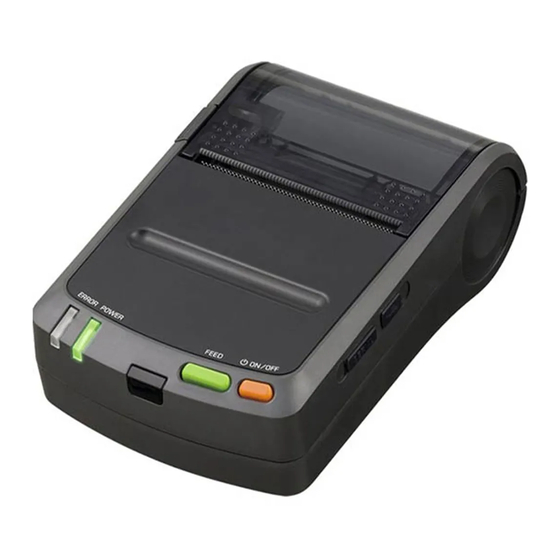
Page 12: Figure 2-1 Dimensions
Dimensions Paper Outlet 63.5 Unit : mm Figure 2-1 Dimensions... -
Page 13: Specified Thermal Paper Specifications
2.2 SPECIFIED THERMAL PAPER SPECIFICATIONS Table 2-2 Thermal Paper Provided by SII Item Specifications Model TP-S245L-1 Type Normal paper roll Paper width 58 mm 1 - Outside diameter 38mm max. Paper thickness 59±5μm Printing surface of Paper roll Outside Table 2-3 Specified Thermal Paper Specifications... -
Page 14: Dimensions Of Timing Mark Position
2.2.1 Dimensions of Timing Mark Position 58 +0/-1.0 Unavailable pre-print area b. Cut Position a. Print start position Unit : mm Figure 2-2 Dimensions of Timing Mark Position (Back of thermal paper) - Page 15 (1) Example of use of the marked paper roll An examples of use of the marked paper roll shown Figure 2-2 is explained as below. (a) Set the function setting of Paper Mode to “Mark Roll Paper”. (b) Insert the thermal paper. (c) Set the page length as the length from the beginning of the current mark to the beginning of the next mark.
-
Page 16: Specified Battery Pack Specifications
2.3 SPECIFIED BATTERY PACK SPECIFICATIONS Item Specification Model BP-L0715-A1-E Available printing lines 20000 lines min. Battery Cycle Life 300 cycles *1: 25C, character spacing is 4 dots, line spacing is 34 dots, TF50KS-E2D selection, print density is 100%, continuous printing with 'H' 1-byte characters, serial communication, fully charged with 8.4 V by specified battery charger. *2: 25C, charged in the printer with specified AC adapter, print ratio is 12.5%, charged with 70%* or more of fully charged. -
Page 17: Precautions For Use
2.4 PRECAUTIONS FOR USE Always print the two-dimensional bar code and ladder bar code (its bar is to be printed verticality to the printer) within 0 to 40°C to ensure the bar code's reading accuracy. The two-dimensional bar code and ladder bar code printing always requires the low speed mode to ensure its reading accuracy. - Page 18 When handling this product, be aware of static electricity. If the static electricity is discharged, this could case communication failure. When this problem occurs, disconnect the USB connector that is connected to the host device and wait few seconds before connect it again. ...
-
Page 19: Interface
CHAPTER 3 INTERFACE This chapter describes 4 types of the interface specifications which are required to connect the host device with the printer. Irrespective of the interface used, amount of the input buffer in the printer is 4k bytes, and transmission buffer is 768 bytes. - Page 20 (3) Connector 3260-8S3: HIROSE ELECTRIC CO., LTD. or equivalent (4) Examples of connection with the host device (a standard personal computer) Printer Host device Printer Host device N.C. 1 1 F.G N.C. 1 TXD 2 2 TXD TXD 2 2 RXD RXD 3 3 RXD RXD 3...
- Page 21 (6) Data transmission Busy control In Busy Control, the conditions which transmit status information to the host device from the printer are as follows; When CTS Control of function setting sets to Enable, the printer sends data from TXD after confirming CTS status as SPACE.
-
Page 22: Usb Interface Specifications
3.2 USB INTERFACE SPECIFICATIONS (1) General specifications Item Specification USB Version Ver 2.0 conformity USB Printing class specification Communication speed Full speed(12Mbps) Communication protocol Bulk transfer (2) Pin assignment Pin No. Name Function Vbus USB power supply USB data signal USB data signal N.C. -
Page 23: Infrared Interface Specifications
3 to 40 s (2) Services supported by IrLAP 1. Connect service 2. Data service 3. Disconnect service IrLAP does not support a transfer for non-number and sniffing services. The printer does not initiate connections. Service Hint Printer, IrCOMM Device Nickname DPU-S245... - Page 24 (3) Services supported by IrLMP 1. Connect service 2. Disconnect service 3. Data service A single LSAP address does not support multiple connections. Furthermore, LSAP address 7 and 9 can not share the connection state. If multiple connections are requested, a disconnect request is transmitted and the printer waits until it receives a disconnect command.
- Page 25 (6) IrCOMM Supports 3-Wireraw, IrLPT, 3-Wire and 9-Wire. Flow control is performed only by the IrLAP layer when connecting with 3-Wireraw or IrLPT. Flow control is performed by the TinyTP layer when connecting with 3-Wire or 9-Wire. Xon/off control and line status control are not supported. (7) Command response processing during IrDA transmission If the printer receives a command that requires transmission of data from the remote station during IrDA transmission, and then stores the data in the transmission buffer and transfers them at transmit timing to...
-
Page 26: Bht-Ir Specifications
3.3.3 BHT-Ir Specifications The printer also supports BHT-Ir communication specified by DENSO CORPORATION. The printer can receive data from the 'BHT-6500' made by DENSO CORPORATION when Data Input Mode SWDIP2-1 and SWDIP2-2 is selected to BHT-Ir. The inherent processing of the printer for BHT-Ir communication is shown below: See BHT-Ir protocol specification for details of the protocol. -
Page 27: Bluetooth Interface Specifications
Profile PIN code None (default) Device name DPU-S245 (default) *1: can be changed by the command (2) Security The printer does not set with PIN code or the Link Key in default. Bluetooth device uses security mode 1, so no encryption is used. -
Page 28: Function Settings
CHAPTER 4 FUNCTION SETTINGS 4.1 FUNCTION SETTING The communication method, a paper types, and so on can be preset in this printer. Preset these functions before using the printer. The function settings of the printer are stored in FLASH memory. Once these are set, these are stored until changing again. -
Page 29: Function Settings(Swdip1)
4.1.1 Function Settings(SWDIP1) Table 4-1 Function Settings (SWDIP1) Value SWDIP Function Data Control Xon/Xoff Busy Stop Bit 2 bits 1 bit Parity See table below Bit Length 7 bits 8 bits Baud Rate See table below Data Control selection Select flow control in serial communication as BUSY (hardware) control or Xon/Xoff control. -
Page 30: Baud Rate Selection
Baud Rate selection Select Baud Rate of communications as Serial and BHT-Ir. Baud Rate SWDIP1-3 SWDIP1-2 SWDIP1-1 1200* 2400 4800* 9600 19200 38400 57600 115200 * This setting is enabled only when Serial is selected as the communication mode. When BHT-Ir is selected as the communication mode, the baud rate is set to 2400 bps automatically. -
Page 31: Function Settings(Swdip2)
4.1.2 Function Settings(SWDIP2) Table 4-2 Function Settings (SWDIP2) Value SWDIP Function Auto Status Output Enable Disable Kanji Code Shift-JIS Code JIS Code Font Size 16 dots 24 dots Auto Power Off Enable Disable Character Set IBM Compatible Reserved Fix to 1 Data Input Mode See below ... - Page 32 Data Input Mode selection Select the communication method. Refer to CHAPTER 3 INTERFACE for more detail. Data Input Mode SWDIP2-2 SWDIP2-1 BHT-Ir/USB Serial/USB IrDA/USB Bluetooth/USB * * This setting is enabled for Bluetooth-supporting model only. Bluetooth-supporting model is shipped with this setting value (Bluetooth/USB).
-
Page 33: Function Settings(Swdip3)
4.1.3 Function Settings(SWDIP3) Table 4-3 Function Settings (SWDIP3) Value SWDIP Function Paper Mode See table below Print Density See table below Paper Select See table below Paper Mode selection Select Paper Mode as the thermal paper in use. Paper Mode SWDIP3-8 Roll Paper Mark Roll Paper... - Page 34 Print Density selection Normally, select the print density as 100%. Print Density SWDIP3-7 SWDIP3-6 100% 105% 110% (NOTE) If too much energy is applied to the thermal head, it would shorten its life span and cause the paper feed problem. Set an accurate thermal paper selection and print density.
-
Page 35: Function Settings(Swdip4)
4.1.4 Function Settings(SWDIP4) Table 4-4 Function Settings (SWDIP4) Value SWDIP Function Bluetooth Link Key Selection Enable Disable (Bluetooth Link Key) Reserved Fix to 1 Busy Output When Error Unbusy Busy Occurs (Error) Mark Position Correct Enable Disable Bluetooth Baud Rate See below CTS Control Enable... - Page 36 Bluetooth Baud Rate selection Select Bluetooth Baud Rate in Bluetooth communication. Usually, select Bluetooth baud rate to 230400bps. Bluetooth Baud Rate SWDIP4-4 SWDIP4-3 230400 bps 57600 bps 115200 bps 230400 bps CTS Control selection When CTS Control selection sets to Enable and Data Control SWDIP1-8 is selected to Busy, the printer transmits data after identifying CTS of the host device as SPACE.
-
Page 37: Function Settings By Switch Operation
4.1.5 Function Settings by Switch Operation A function setting can be performed by switch operation. Use the function settings by switch operation in the function settings mode of the printer. Operate the following procedures to enter the printer to the function settings mode. (a) Be sure that the thermal paper is set to the printer and the printer is turned off. - Page 38 (1) Initializing SWDIP switch settings (a) When the following message is printed in the function setting mode, press the FEED switch. Load Default Setting? Yes: Feed SW / No: Power SW (b) When the following message is printed, the printer turns off. The settings are set to defaults.
-
Page 39: Function Settings By Commands
Operation 2: SWDIP switch setting (a) When the message shown at the following is printed, set the bits from the most significant bit (SWDIP*-8) to the least significant bit (SWDIP*-1). Input 8 bits. 1: Feed SW / 0: Power SW To set 1: Press the FEED switch. -
Page 40: Test Print
4.2 TEST PRINT The printer has a test print function that prints the contents of the Function Settings and character strings for test. (a) Be sure that the thermal paper is set to the printer and the printer is turned off. If the thermal paper is not set, set the thermal paper to the printer. -
Page 41: Hex Dump Mode
4.3 HEX DUMP MODE This function can be used to check whether the host device transmits data to the printer correctly. Perform the following steps. (a) Be sure that the thermal paper is installed to the printer and the printer is turned off. (b) Keep on pressing the POWER and FEED switches in six seconds. - Page 42 Press the POWER switch to exit the HEX dump printing. Hint Some BASIC use a PR# statement instead of PRINT#. Refer to the computer manual for details on BASIC. 4-15...
-
Page 43: Lamp Display And Switch Function
CHAPTER 5 LAMP DISPLAY AND SWITCH FUNCTION This chapter explains printer status by lamp display and functions of switches. 5.1 PRINTER STATE LAMP DISPLAY Table 5-1 lists states of the printer, display that by two lamps (POWER and ERROR lamps). Table 5-1 Printer Status Signals Display Printer status... -
Page 44: Error Recovery Procedure
5.2 ERROR RECOVERY PROCEDURE When an error occurs, the printer stops printing operation. Moreover, when Busy Output When Error Occurs is enabled in the Function Settings, the status of data reception becomes busy. However, some errors can be recovered to a status just before a printing stop after clearing errors. Error recovery procedure is shown below. -
Page 45: Power Switch
5.3 POWER SWITCH Turning ON / OFF the printer and changing the mode to the print-ready can be performed by the POWER switch. (NOTE) Always use the POWER switch to turn off the printer. Do not power off the printer by removing the AC adapter or the battery pack. If doing so, the memory may be damaged. -
Page 46: Command Descriptions
CHAPTER 6 COMMAND DESCRIPTIONS This chapter describes the functions of the commands supported by the printer. 6.1 THE SUMMARY OF COMMAND FUNCTION The commands of DPU-S245 conform to the ESC/P. Table 6-1 Command Summary (1/4) Command Function Page ESC 'C'... - Page 47 Table 6-1 Command Summary (2/4) Command Function Page ESC 'R' Select International Character 6-31 ESC 't' Select Character Code Table 6-31 DC2 'y' Euro Character Specify 6-32 ESC '%' Set/Cancel Download Character Set 6-34 ESC '&' Define Download Characters 6-34 DC2 'D' Download Characters Area Operation 6-35...
- Page 48 Table 6-1 Command Summary (3/4) Command Function Page DC3 '+ Ruler Line ON 6-62 DC3 '-' Ruler Line OFF 6-62 DC3 'A' Ruler Line Buffer A 6-62 DC3 'B' Ruler Line Buffer B 6-62 DC3 'C' Ruler Line Buffer Clear 6-63 DC3 'D' Define Ruler Line by Dot...
- Page 49 Table 6-1 Command Summary (4/4) Command Function Page DC2 '$' '1' Rectangle Print 6-88 DC2 '$' '2' Line Type Property 6-89 DC2 '$' '3' Line Width Property 6-89 DC2 '$' '4' Fill Property 6-89 DC2 'e' Enable/Disable Automatic Status Transmission 6-91 DC2 'r' Send Remaining Memory Capacity...
-
Page 50: Function Codes
6.2 FUNCTION CODES One of the following control codes is attached to the beginning of each command. These control codes are also called function codes. HT(09H), LF(0AH), VT(0BH), FF(0CH), CR(0DH), SO(0EH), DC2(12H), DC3(13H), DC4(14H), CAN(18H), ESC(1BH), FS(1CH), GS(1DH) Function codes may or may not have parameters or image data. The number of bytes per command differs based on the type of command. - Page 51 - Second byte (If the first byte is 00H) 20H - 7EH: The codes are processed as 1-byte character in the Kanji ROM. 80H - FEH: The codes are processed as 1-byte character in the Kanji ROM. FFH: It differs from each character set. If the extended graphics character set or the katakana character set are selected, they are ignored with the first byte.
-
Page 52: Shift Jis Code System
(If the first byte is A1H to FDH) A1H - FEH: The codes are processed as the second byte of Korean. If the codes other than the above are not commands, these codes are ignored with the first byte. The next data to be received is processed as the first byte. 6.3.2 Shift JIS Code System If the Shift JIS Code System is selected with the Kanji Code System Select command, Kanji characters can be printed with 2-byte character codes without entering the Kanji Mode Specify command. - Page 53 (3) 2-byte character codes when mounting Korean character 2-byte character codes specify Korean or User-defined characters. - First byte A0H: User-defined character area. A1H - FDH: Korean characters area when selecting Korean. The codes other than the above are ignored and processed as 1-byte character. - Second byte (If the first byte is A0H) A1H - FEH:...
-
Page 54: Memory
6.4 MEMORY Check remaining memory size when using optional fonts, routine command or stamp. Refer to this section to use those functions. 6.4.1 External RAM Memory (1) Memory area The printer has 232280 bytes of memory for User-defined characters, downloaded characters, optional fonts, routine command and stamp. -
Page 55: Table 6-4 Commands For Allocating Or Freeing Memory Area
(2) Capacity of memory size Allocated memory size depend on used function. User-defined character and downloaded character is allocated size of 9784 and 6248 bytes respectively. Optional fonts, routine function or stamp is allocated size of (number of data + Memory control Information). Moreover, registration of routine function and stamp requires the above-mentioned size per registration data. -
Page 56: Table 6-5 Gs 'P' 0 Used Memory Capacity Of Pdf417 Print Command
When the command is normal and memory area has been allocated, but the bar code cannot be printed within printable area: The command is ignored. When the command is normal, memory area has been allocated and the bar code can be printed within printable area: The two-dimensional bar code is printed. -
Page 57: Table 6-6 Gs 'P' 1 Used Memory Capacity Of Qr Code Print Command
(b) Used Memory Capacity of QR Code The total empty area of area1 to 3 shown in Table 6-6 is necessary for QR Code print. For an example, when number of bar code data byte=30, model=2, and version=4; Area1 = 302+560 = 620 bytes Area2 = 8006 bytes ... -
Page 58: Table 6-7 Gs 'P' 2 Used Memory Capacity Of Data Matrix Print
(c) Used Memory Capacity of Data Matrix The total empty area of area1 to 4 shown in Table 6-7 is necessary for Data Matrix print. For an example, when number of bar code data byte =20 and symbol size=22 (vertical) 22 (horizontal);... -
Page 59: Table 6-8 Data Matrix Symbol Sizes
Table 6-8 Data Matrix Symbol Sizes Symbol size Map matrix size Number of the Code Word Vertical Horizontal Vertical Horizontal Data Error correction 1050 1304 1558 6-14... -
Page 60: Table 6-9 Gs 'P' 3 Used Memory Capacity Of Maxicode Print
(d) Used Memory Capacity of MaxiCode The total empty area of area1 to 2 shown in Table 6-9 is necessary for MaxiCode print. For an example, when number of bar code data byte=33; Area 1 = 33+1 = 34 bytes Area 2 = 7684 bytes Total = 7718 bytes (Empty area size is an even byte number.) -
Page 61: Flash Memory
6.4.2 FLASH Memory The printer stores data such as User-defined character, downloaded character, optional font, routine function, stamp and template data into FLASH memory. Of these data, User-defined character, downloaded character, optional font and template data can be used dedicated memory area. Moreover, FLASH memory has shared memory area as 256K byte user area for routine function and stamp. - Page 62 When data storage and release are repeated, the memory state turns to the [4] state. To use the “Released state (Erasable state)” area again, execute the User Area Defragment (DC2 '*' '1') command. The [5] shows the memory state after the command is executed. Executing Remaining User Area Response (DC2'*' '2') command to check the current remaining area.
-
Page 63: Command Description
6.5 COMMAND DESCRIPTION Each command for the printer is described respectively. This section explains each command. 6.5.1 Command Format Each command is described in the following format. 6-18... -
Page 64: Formatting Commands
6.5.2 Formatting Commands ESC 'C' n Set Page Length at n Lines Code 1BH 43H n 1 n 127 Function Set page length at n lines. The page length is (current line spacing x n) dot lines. If the line spacing is zero, this command is ignored. The current position becomes the beginning of the page. - Page 65 ESC 'O' Cancel Bottom Margin Code 1BH 4FH Function Cancels bottom margin. If the page length is not specified in the initial state in the Roll Paper mode, this command is ignored. Default The bottom margin is canceled. Top of the page Printable area The defined page length...
- Page 66 ESC 'I' n Set Left Margin Code 1BH 6CH n 0 n 255 Function Sets the left margin at n columns from the left edge (first column). Column n (current character pitch x n) from the left edge becomes the left margin. The character width includes character spacing.
-
Page 67: Figure 6-1 Program Sample 1
100 OPEN "COM1:9600,N,8,1" FOR OUTPUT AS #1 110 PRINT #1,"Page Length : 5 line" 120 PRINT #1,"Skip Length : 2 line" 130 PRINT #1,"Right Margin : 17 char" 140 PRINT #1,"Left Margin : 5 char" 150 PRINT #1,CHR$(&H0D); 160 PRINT #1,CHR$(&H1B);"C";CHR$(5); 'Page Length : 5 line 170 PRINT #1,CHR$(&H1B);"N";CHR$(2);... -
Page 68: Line Spacing Commands
6.5.3 Line Spacing Commands ESC '0' Set 1/8-inch Line Spacing Code 1BH 30H Function Sets the line spacing amount to 1/8 of an inch (26 dots lines). If the line buffer contains data and the line spacing amount is smaller than the character height, the data in the buffer is printed and line feeding is performed by the character height. -
Page 69: Figure 6-3 Program Sample 2
100 OPEN "COM1:9600,N,8,1" FOR OUTPUT AS #1 110 PRINT #1,CHR$(&H1B);"0"; 120 PRINT #1,"1/8 inch line space" 130 PRINT #1,CHR$(&H1B);"2"; 140 PRINT #1,"1/6 inch line space" 150 FOR I=0 TO 96 STEP 24 160 PRINT #1,CHR$(&H1B);"3";CHR$(I); 170 PRINT #1,";I;"dot-line line space" 180 NEXT I 190 PRINT #1,"---------------------------------------"... -
Page 70: Tab Setting Commands
6.5.4 Tab Setting Commands ESC 'B' {DATA} NUL Set Vertical Tab Positions Code 1BH 42H {p1 p2••• pk} 00H 1 p 255 0 k 16 Function Sets the vertical tab position. The tab position is the (current line spacing × p lines) dot position with respect to the page starting position. - Page 71 ESC 'D' {DATA} NUL Set Horizontal Tab Positions Code 1BH 44H {p1 p2•••pk} 00H 1 p 255 1 k 32 Function Sets horizontal tab positions. The tab position is the (current character with × p columns) position with respect to the left margin.
-
Page 72: Print And Paper Feed Commands
6.5.5 Print and Paper Feed Commands Print and Carriage Return Code Function Functions the same as an LF command. If the line buffer contains data and the line spacing amount is smaller than the character height, the data in the buffer is printed and line feeding is performed by the character height. Print and Line Feed Code Function After data in the line buffer is printed out, the printer feeds one line. - Page 73 ESC 'J' n Print and Feed paper Code 1BH 4AH n 0 n 255 Function Prints the data in the print buffer and feeds the paper one dot line. If the line buffer contains data and n is smaller than the character height, the data in the line buffer is printed and one line is fed by the character height.
-
Page 74: Print Position Commands
6.5.6 Print Position Commands Execute Horizontal Tab Code Function Moves the print position to the next horizontal tab position. This command is ignored if the next horizontal tab position is not set. This command is ignored if the next horizontal tab position exceeds the right margin. The horizontal tab position is set using the ESC 'D' command. -
Page 75: Figure 6-5 Program Sample 3
100 OPEN "COM1:9600,N,8,1" FOR OUTPUT AS #1 110 PRINT #1,CHR$(&H1B);"2"; 120 PRINT #1,CHR$(&H1B);"C";CHR$(25); 130 PRINT #1,CHR$(&H1B);"B";CHR$(3);CHR$(6);CHR$(9);CHR$(12);CHR$(0); 140 PRINT #1,CHR$(&H1B);"D";CHR$(10);CHR$(20);CHR$(0); 150 PRINT #1," Page top " 160 PRINT #1,"Carrige Return + CR";CHR$(&H0D); 170 PRINT #1,"Line Feed + LF";CHR$(&H0A); 180 PRINT #1,"100 dot-line feed + ESC+J";CHR$(&H1B);"J";CHR$(100); 190 PRINT #1,"Vertical Tab + VT";CHR$(&H0B);... -
Page 76: 1-Byte Character Set Selection Commands
6.5.7 1-byte character Set Selection Commands ESC 'R' n Select International Character Code 1BH 52H n 0n12 Function n selects an international character set from the following table. Country U.S.A. France Germany U.K. Denmark I Sweden Italy Spain Japan Norway Denmark II Spain II Latin America... - Page 77 DC2 'y' n Euro Character Specify Code 12H 79H n n=0, 32 n 254 (except 127) Function Exchanges the font of character code n of the one-byte system to Euro characters. When n is 0, the exchange to the Euro characters is released and the font returns before selection.
-
Page 78: Figure 6-7 Program Sample 4
100 OPEN "COM1:9600,N,8,1" FOR OUTPUT AS #1 110 PRINT #1,CHR$(&H1B);"$";CHR$(&HD8);CHR$(0);"23 24 40 5B 5C 5D 5E 60 7B 7C 7D 7E" 120 FOR I=0 TO 12 130 RESTORE 310 140 FOR J=0 TO I READ CNTRY$ 160 NEXT J 170 PRINT #1,CNTRY$;CHR$(&H1B);"$";CHR$(&HA8);CHR$(0);:GOSUB 250 180 NEXT I 190 FOR I=0 TO 1 200 PRINT #1,CHR$(&H1B);"t";CHR$(I);... -
Page 79: 1-Byte Characters Definition Commands
6.5.8 1-byte characters Definition Commands ESC '%' n Set/Cancel Download Character Set Code 1BH 25H n Function Sets or cancels the download character set. Only the least significant bit of n is valid. n = 0: Cancel the download character set. n = 1: Set the download character set. - Page 80 •24-dot font •16-dot font 16 dots 8 dots 16 dots 24 dots DC2 'D' n Download Characters Area Operation Code 12H 44H n Function Allocates or frees the download character area. Only the least significant bit (LSB) of n is valid. n = 0 : Frees the download character area.
-
Page 81: Character Decoration Commands
6.5.9 Character Decoration Commands Select Expanded Character Mode with Automatic Cancellation Code Function Prints 1-byte characters and 2-byte characters following this code in double-width characters. This mode is canceled by DC4, LF, VT, FF, ESC 'W', GS '<' or CR, or by buffer-full printing. When the line buffer is cleared, the expanded character mode is canceled. - Page 82 ESC 'F' Cancel Emphasized Print Mode Code 1BH 46H Function Cancels the emphasized print mode for 1-byte characters and 2-byte characters. The emphasized print mode can also be selected or canceled with ESC '!', but the most recently processed command is effective. The double print mode is also canceled.
- Page 83 ESC '!' n Set Print Mode Code 1BH 21H n Function Sets a print mode for 1-byte characters. Each bit of n is used as follows: Function Undefined Undefined Undefined Emphasized printing Canceled Double printing Canceled Double-width Canceled Undefined Underline Canceled The underline is attached to all character widths, including character right-side spacing.
- Page 84 DC2 'Y' n Character Rotation Code 12H 59H n Function Selects the direction of rotation of 1-byte characters and 2-byte characters. Only two low-order bits are valid. n = 0: Cancel character rotation. n = 1: Rotate the character 90° clockwise. n = 2: Rotate the character 90°...
-
Page 85: Character Pitch Adjustment Command
6.5.10 Character Pitch Adjustment Command ESC SP n Set Character Spacing Code 1BH 20H n 0 n 127 Function Sets the character right-side spacing for 1-byte characters in dot units (n). If a character code is input after this command, it is printed with (character width + set character spacing). -
Page 86: Figure 6-9 Program Sample 5
100 OPEN "COM1:9600,N,8,1" FOR OUTPUT AS #1 110 PRINT #1,CHR$(&H12);"F0"; '16 dots font 120 PRINT #1,CHR$(&H1B);"&";CHR$(0);"DD"; 130 RESTORE 460 : N=16 : GOSUB 430 140 PRINT #1,CHR$(&H12);"F1"; '24 dots font 150 PRINT #1,CHR$(&H1B);"&";CHR$(0);"oo"; 160 RESTORE 480 : N=48 : GOSUB 430 170 PRINT #1,CHR$(&H1B);"%1";... -
Page 87: Figure 6-10 Print Sample 5
Figure 6-10 Print Sample 5 6-42... -
Page 88: Kanji Character Set Selection Commands
Function Selects Kanji mode. In Kanji mode, only 2-byte character codes are accepted. 1-byte character in SII Japanese font set (at shipping) can be printed by entering 00H + 1-byte code. This command is ignored when Shift-JIS is selected as the Kanji code system. - Page 89 The Kanji quarter size character mode can be canceled with the Cancel Kanji Mode (FS '.') command. For character font, see the Appendix A.4 Kanji quarter size character set. This command is valid for SII Japanese font set (at shipping) mounted. Default Cancel Kanji Quarter Size Character Mode.
-
Page 90: Kanji Character Definition Commands
6.5.12 Kanji Character Definition Commands FS '2' c1 c2 {DATA} Define User-defined Character Code 1CH 32H c1 c2 {d1 d2•••dk} Function Defines a Kanji User-defined character pattern for the character code specified by c1 and c2. c1 and c2 indicate a Kanji code for the User-defined character to be defined. c1 indicates the first byte, and c2, the second byte. - Page 91 DC2 'G' n User-defined Character Area Operation Code 12H 47H n Function Allocates or frees up the User-defined character area. Only the least significant bit (LSB) of n is valid. n = 0: Frees up the User-defined character area. n = 1: Allocates the User-defined character area. When the User-defined character area is freed up, the User-defined character is erased and the User-defined character definition commands are ignored.
-
Page 92: Kanji Character Decoration Commands
6.5.13 Kanji Character Decoration Commands FS 'J' Select Vertical Writing Code 1CH 4AH Function Selects vertical writing. Valid in Kanji mode only. Character decoration applies to a line. If the vertically written character is doubled vertically, it is doubled in the Y direction (character widths are doubled). If the width is doubled, the character is doubled in the X direction (characters are doubled vertically). - Page 93 FS '-' n Select/Cancel Kanji Underline Mode Code 1CH 2DH n Function Select or cancel underline mode. Only the low two bits of n is valid. n = 0: Cancel underline mode. n = 1: Select 1-dot underline mode. n = 2: Select 2-dot underline mode. n = 3: Ignore the command.
- Page 94 FS '!' n Set Kanji Print Mode Code 1CH 21H n Function Sets a print mode for 2-byte characters. Each bit of n is used as follows: Function Printing direction selection Horizontal writing Vertical writing Undefined Double-width Canceled Double height Canceled Kanji quarter size character Canceled...
-
Page 95: Kanji Character Pitch Adjustment Command
6.5.14 Kanji Character Pitch Adjustment Command FS 'S' nl nr Set Kanji Left- and Right-side Spacing Code 1CH 53H nl nr 0 nl 127 0 nr 127 Function Sets the left-side spacing nl and the right-side spacing nr of 2-byte characters. Only the seven least significant bits of nl and nr are valid. -
Page 96: Figure 6-11 Program Sample 6
100 OPEN "COM1:9600,N,8,1" FOR OUTPUT AS #1 110 GJ$=CHR$(&H77)+CHR$(&H21) 120 PRINT #1,CHR$(&H12);"F0"; '16 dots font 130 PRINT #1,CHR$(&H1C);"2";GJ$; '7721H 140 RESTORE 570 : N=32 : GOSUB 540 150 PRINT #1,CHR$(&H12);"F1"; '24 dots font 160 PRINT #1,CHR$(&H1C);"2";GJ$; '7721H 170 RESTORE 600 : N=72 : GOSUB 540 180 FOR I=&H30 TO &H33 '2330 ~... -
Page 97: Figure 6-12 Print Sample 6
Figure 6-12 Print Sample 6 6-52... -
Page 98: Image Command
6.5.15 Image Command ESC '*' m nl nh {DATA} Set Bit Image Mode Code 1BH 2AH m nl nh {d1 d2•••dk} m: 0,1,32,33 (mode setting) 0 nh×256 + nl 4095 Function Sets the bit image mode and prints bit image. m indicates the bit image mode. - Page 99 •8-dot mode •24-dot mode Bit image data Bit image data Print data Print data 6-54...
- Page 100 GS 'v' '0' m xl xh yl yh {DATA} Raster Bit Image Print Code 1DH 76H 30H m xl xh yl yh {d1 d2•••dk} m=0 or 48 0 xh x 256 + xl 65535 0 yh x 256 + yl 65535 Function Prints raster format dot images.
-
Page 101: Figure 6-13 Program Sample 7
100 OPEN "COM1:9600,N,8,1" FOR OUTPUT AS #1 110 D=408:N=D 120 PRINT #1,"8 dots Single-density 130 PRINT #1,CHR$(&H1B);"*";CHR$(0);CHR$(D MOD 256);CHR$(D\256); 140 GOSUB 260 150 N=D : PRINT #1,"8 dots Double-density 160 PRINT #1,CHR$(&H1B);"*";CHR$(1);CHR$(D MOD 256);CHR$(D\256); 170 GOSUB 260 180 N=D*3 : PRINT #1,"24 dots Single-density 190 PRINT #1,CHR$(&H1B);"*";CHR$(32);CHR$(D MOD 256);CHR$(D\256);... - Page 102 6.5.16 Stamp Stamp function does overlap characters with predefined bit images and to print out them simultaneously. Since the memory stores the defined stamps unless initializing the user area of the memory or clearing the stamp, repeating print of the same stamp is possible without entering a large amount of data repeatedly. Create bit image in the rectangular area which is specified by a number of bytes in the horizontal direction and a number of dot lines in the vertical direction.
- Page 103 DC2 'T' n x yl yh {Image Data} Stamp Define Code 12H 54H n x yl yh {d1 d2•••dk} 0 n 127 1 x 127 1 yhx256+yl 2047 Function Specify the stamp images. Specify the stamp number between 00H and 7FH (0 to 127) to n. The stamp number is any number.
- Page 104 DC2 'S' n x Stamp Select Code 12H 53H n x 0 n 127 0 x 255 Function Selects stamp and specifies the printing position to the horizontal direction. n: Stamp number (00H to 7FH) x: Printing position in the horizontal direction (by 8 dots) (00H to FFH) x specifies the printing position to the horizontal direction.
-
Page 105: Stamp
100 Open "COM1:9600,N,8,1" For Random As #1 110 S$ = String$(20, Chr$(&HFF)) + String$(6, Chr$(0)) + String$(20, Chr$(&H55)) 120 Print #1, Chr$(&H12); "T"; Chr$(10); Chr$(20); Chr$(160); Chr$(0); 130 For i = 1 To 20: For j = 0 To 7 140 Print #1, Mid$(S$, i + j, 20);... -
Page 106: Other Commands
6.5.17 Other Commands Cancel Print Data in Buffer Code Function Clears the data in the line buffer. The next print starting position is the beginning of the line (left margin). 100 OPEN "COM1:9600,N,8,1" FOR OUTPUT AS #1 110 PRINT #1,CHR$(&H1B);"Q";CHR$(40); 'Right Margin 40 char 120 PRINT #1,CHR$(&H1B);"l";CHR$(10);... -
Page 107: Ruler Line Commands
6.5.18 Ruler Line Commands DC3 '+' Ruler Line ON Code 13H 2BH Function Turns on ruler line printing. After this command is input, the printer prints the contents of the ruler line buffer with a character print or paper feed command until the DC3 '-' command or DC3 'C' command is input. When characters are printed, characters and ruler lines are overlapped with each other in the mode specified by DC2 '#'. - Page 108 DC3 'C' Ruler Line Buffer Clear Code 13H 43H Function Clears all bits in the selected line buffer to zero. If all bits in the selected line buffer are set to zero, the data is not printed even when the ruler line printing is turned on.
- Page 109 DC3 'V' {DATA} Ruler Line LSB/MSB Image Code 13H 56H {d1 d2••• dk} 0 d 255 Function Writes one dot line of the image data into the selected ruler line buffer. The image data k corresponds to the line of dots in a ruler line buffer. When the page mode is not selected, number of image data is 48 bytes.
-
Page 110: Figure 6-19 Program Sample 10
100 Open "COM1:9600,N,8,1" For Output As #1 110 Print #1, Chr$(&H13); "A"; 120 Print #1, Chr$(&H13); "V"; 130 Print #1, String$(24, Chr$(&H88)); 140 For I = 1 To 24: Print #1, Chr$(I);: Next I 150 Print #1, Chr$(&H13); "+"; 160 Print #1, "RULED LINE OR" 170 Print #1, Chr$(&H12);... -
Page 111: Optional Font Commands
6.5.19 Optional Font Commands DC2 'P' s e x y {DATA} Define Optional Font Code 12H 50H s e x y {d1 d2•••dk} 20H s e FEH s 7FH, e 7FH 8 x 127 1 ... - Page 112 20 dots 20 dots * shadow area is ignored Order of Optionnal font data input (x=20、y=20) Default No definition. DC2 'O' n Select Optional Font Code 12H 4FH n Function Selects an optional font. Only the least significant bit of n is valid. n = 0: Cancel the optional font.
-
Page 113: Figure 6-21 Program Sample 11
100 OPEN "COM1:9600,N,8,1" FOR OUTPUT AS #1 110 SCD=&H41:ECD=&H45 120 PRINT #1,CHR$(&H12);"P";CHR$(SCD);CHR$(ECD);CHR$(16);CHR$(8); 'A~E 130 FOR I=0 TO ECD-SCD 140 RESTORE 280 : N=16 : GOSUB 250 150 NEXT I 160 FOR I=0 TO 1 170 PRINT #1,CHR$(&H12);"O";CHR$(I); 180 FOR J=0 TO 1 PRINT #1,CHR$(&H1B);"W";CHR$(J);... -
Page 114: Bar Code Commands
6.5.20 Bar Code Commands GS 'H' n Select HRI Character Print Position Code 1DH 48H n Function Selects the print position of the HRI character when printing a bar code. Only the two low-order bits of n are valid. n = 0: Does not print n = 1: Above the bar code n = 2: Below the bar code n = 3: Above and below the bar code... - Page 115 GS 'k' n {DATA} Print Bar Code Code 1DH 6BH n {d1 d2•••dk} 0 n 255 Function Selects a bar code system and prints a bar code. n: Bar code system (Only the 4 least significant bits of n are valid.) Function UPC-A UPC-E...
- Page 116 GS 'w' n1 n2 Set Width of Bar Code Code 1DH 77H n1 n2 0 n1 255 0 n2 255 Function Specifies the bar code narrow width and wide width in dots. The two low-order bits of n1 and n2 are valid. They are set as follows: Narrow width Wide width Dots...
- Page 117 GS 'o' n PDF Row Height Code 1DH 6FH n 2 n 85 Function Sets a PDF row height by dot. n:PDF417 row height in a dot number. Sets PDF417 row height n dots. When a small value is set as the row height, some bar code reader may not read. Normally, set 3 dots or more.
- Page 118 DC2 ';' n QR Code and Data Matrix Module Sizes Code 12H 3BH n 2≤n≤11 Function Sets QR Code and Data Matrix module sizes by dot. Number of dots on one side of the module. Sets module sizes of QR Code and Data Matrix to n dots. When a small value is set as the module size, some bar code readers may not read.
- Page 119 When the position of bar code end is not placed within the page length and exceeds the print area set by bottom margin setting, the printer prints bar code after executing Form Feed. The bar code print position setting is valid. The quiet zone width is fixed to four modules.
- Page 120 GS 'p' 3 mode ….n {DATA} MaxiCode Print Code 1DH 70H 03H 02H sc cc pc n {d1 d2•••dk} (mode2) 1DH 70H 03H 03H sc cc pc n {d1 d2•••dk} (mode3) 1DH 70H 03H 04H n {d1 d2•••dk} (mode4) 1DH 70H 03H 05H n {d1 d2•••dk} (mode5) Function Prints the MaxiCode data based on the specified contents.
-
Page 121: Figure 6-23 Program Sample 12
110 OPEN "COM1:9600,N,8,1" FOR OUTPUT AS #1 120 PRINT #1,"***** BARCODE TEST *****" 130 FOR I=0 TO 7 140 RESTORE 380 150 FOR J=0 TO I READ CODE$ 'Get Code Name 170 NEXT J 180 RESTORE 400 190 FOR J=0 TO I READ DAT$ 'Get Bar Data 210 NEXT J 220 PRINT #1,CHR$(&H1D);"w";CHR$(I MOD 3);CHR$(I MOD 4);... -
Page 122: Figure 6-24 Print Sample 12
Figure 6-24 Print Sample 12 6-77... -
Page 123: Figure 6-25 Program Sample 13
100 OPEN “COM1:9600,N,8,1” FOR OUTPUT AS #1 110 PRINT #1, "*****PDF417*****" 120 PRINT #1, CHR$(&H1D);"n";CHR$(3); 'Nominal narrow element width setting 130 PRINT #1, CHR$(&H1D);"o";CHR$(6); 'PDF step height setting 140 PRINT #1, CHR$(&H1D);"P";CHR$(0); 'Barcode print position setting (left end) 150 PRINT #1, CHR$(&H1D);"p";CHR$(0); 'Print of PDF417 160 PRINT #1, CHR$(0);CHR$(2);CHR$(0);CHR$(0);CHR$(50);CHR$(0);... -
Page 124: Figure 6-27 Program Sample 14
100 OPEN “COM1:9600,N,8,1” FOR OUTPUT AS #1 110 FOR I=2 TO 3 120 READ MODE$,SERVICE$,COUNTRY$,POSTAL$ 130 PRINT #1, "*****MaxiCode ";MODE$;"*****" 140 PRINT #1, CHR$(&H1D);"P";CHR$(I MOD 2); 'Barcode print position setting 150 PRINT #1, CHR$(&H1D);"p";CHR$(3); 'Print of MaxiCode (modes 2 & 3) 160 PRINT #1, CHR$(I);SERVICE$;COUNTRY$;POSTAL$;CHR$(50);... -
Page 125: Figure 6-28 Print Sample 14
Figure 6-28 Print Sample 14 6-80... -
Page 126: Routine Commands
6.5.21 Routine Commands The routine commands put character strings and commands in memory and prints data in routine formats. They are a type of macro processes. The routine commands begin with DC2 'E' m and are divided into four types according to the value of m. Only the two low-order bits of m are valid. - Page 127 'V' {d1 d2 ••• dk} NAME : Sets routine image (Same function as DC3 'V' {DATA}) FUNCTION : Stores image data in the selected ruled line buffer. 'P' n NAME : Prints routine dot line (parameter print) n=Repetitive dot lines (0 n 255) FUNCTION : Prints data in the line buffer.
- Page 128 DC2 'E' 1 n dl dh {DATA} Set Routine Parameter Data Code 12H 45H 01H n dl dh {d1 d2•••dk} 0 n 127 0 dhdl 65525 Function Sets character data to be printed in a routine format. n is a routine parameter number.
- Page 129 DC2 'E' 2 n Execute Routine Format Code 12H 45H 02H n 0 n 127 Function Executes a routine format. n is the number of a routine format to be executed. If n is not in the above range, the command is ignored.
-
Page 130: Figure 6-29 Program Sample 15
100 OPEN "COM1:9600,N,8,1" FOR OUTPUT AS #1 110 'Format Set 120 PRINT #1,CHR$(&H12);"E0";CHR$(0);CHR$(7);CHR$(0); 'Format No.0 130 PRINT #1,"ACF";CHR$(&HFF);CHR$(&HFF);"P";CHR$(2); 140 FOR I=1 TO 3 150 PRINT #1,CHR$(&H12);"E0";CHR$(I);CHR$(29);CHR$(0); 'Format No.1-3 160 PRINT #1,"BCL";CHR$(0);CHR$(0);CHR$(1);CHR$(0); 170 PRINT #1,"L";CHR$(79);CHR$(0);CHR$(80);CHR$(0); 180 PRINT #1,"L";CHR$(159);CHR$(0);CHR$(160);CHR$(0); 190 PRINT #1,"L";CHR$(383);CHR$(0);CHR$(384);CHR$(0); 200 PRINT #1,"$";CHR$((I-1)*80);CHR$(0);... -
Page 131: Page Mode
6.5.22 Page Mode The page mode function maintains a rectangular area with an arbitrary size, deploys the printed data there, and prints characters in the normal direction or rotated 90° clockwise. The page mode function allows the user to layout printing material more freely thanks to the above features. DC2 'z' 0 n x yl yh Page Mode Select Code... - Page 132 DC2 'z' 1 Page Mode Print Code 12H 7AH 01H Function Prints the contents of the page area. The printer returns to the standard mode after processing the page mode print. Printing deploys in direction according to Page Mode Select (DC2 'z' 0) command. If the printer is not in the page mode, this command is ignored.
- Page 133 DC2 '$' '1' xsL xsH ysL ysH xeL xeH yeL yeH mode Rectangle Print Code 12H 24H 31H xsL xsH ysL ysH xeL xeH yeL yeH mode 0 xsH × 256+xsL 65535 0 ysH × 256+ysL 65535 0 ...
- Page 134 DC2 '$' '2' n Line Type Property Code 12H 24H 32H n 0 n 2 Function Specifies a line type property. Line type Solid line Long dashed line Short dashed line Default DC2 '$' '3' n Line Width Property Code 12H 24H 33H n 0<n ...
-
Page 135: Figure 6-31 Program Sample 16
100 OPEN "COM1:9600,N,8,1" AS #1 110 S$=”ABCDEFGHIJKLMN” 120 PRINT #1,CHR$(&H12);"z";CHR$(0);CHR$(1);CHR$(40);CHR$(230);CHR$(0); 130 PRINT #1,S$ 140 PRINT #1,CHR$(&H1B);"W1";S$ 150 PRINT #1,CHR$(&H1B);"w1";S$ 160 PRINT #1,CHR$(&H12);"z";CHR$(2);CHR$(160);CHR$(0); 170 PRINT #1,CHR$(&H1D);"P";CHR$(2); 180 PRINT #1,CHR$(&H1D);"H";CHR$(2); 190 PRINT #1,CHR$(&H1D);"h";CHR$(80); 200 PRINT #1,CHR$(&H1D);"k";CHR$(0);”12345678901”;CHR$(0); 210 PRINT #1,CHR$(&H12);"$2";CHR$(1); 220 PRINT #1,CHR$(&H12);"$3";CHR$(2); 230 PRINT #1,CHR$(&H12);"$1";... -
Page 136: Status Commands
6.5.23 Status Commands DC2 'e' n Enable/Disable Automatic Status Transmission Code 12H 65H n Function Select whether to send an error status if an error occurs. Only the least significant bit of n is valid. n = 0: Do not send an error status. n = 1: Send an error status. - Page 137 DC2 'v' Send V Voltage Code 12H 76H Function Measures the V voltage (head and motor Operating voltage) in the printer and sends it. The voltage is transmitted as a 3-bytes code consisting of a 1-digit integer part, a decimal point, and a 1-digit decimal.
- Page 138 DC2 'j' n Execute Response Request Code 12H 6AH n Function Sends the execute response code as n if this command is executed. n: response code (low order 4 bits are valid) This interface has 4K bytes reception buffer and does not handle several operations such as the commands, data input or execution or printing at the same time.
-
Page 139: Figure 6-33 Program Sample 17
100 OPEN "COM1:9600,N,8,1" AS #1 110 PRINT #1,CHR$(&H12);"v"; 120 PRINT #1,"Vp voltage : ";INPUT$(3,#1);" V" 130 PRINT #1,CHR$(&H12);"r"; 140 PRINT #1,"Rest Memory : ";INPUT$(6,#1);"H Byte" 150 PRINT #1,CHR$(&H12);"q"; 160 PRINT #1,"Extend Check Sum :";INPUT$(4,#1);"H" 170 PRINT #1,CHR$(&H12);"l"; 180 PRINT #1,"DIP_SW:";INPUT$(35,#1) 190 PRINT #1,CHR$(&H12);"e1";... -
Page 140: Character Set Command
6.5.24 Character Set Command DC2 'F' n Select Character Font Size Code 12H 46H n Function Sets the character font size to 16 dots or 24 dots. Only the least significant bit of n is valid. n = 0: 16 dots n = 1: 24 dots The character size specified here is applied to 1-byte characters and 2-byte characters. -
Page 141: Figure 6-35 Program Sample 18
100 OPEN "COM1:9600,N,8,1" FOR OUTPUT AS #1 110 FOR I=0 TO 1 120 PRINT #1,CHR$(&H12);"F";CHR$(I); 130 IF I=0 THEN PRINT #1,"16"; ELSE PRINT #1,"24"; 140 PRINT #1," DOT FONT" 150 FOR J=&H41 TO &H5A PRINT #1,CHR$(J); 170 NEXT J:PRINT #1,CHR$(&H0D); 180 PRINT #1,CHR$(&H1C);"&";... -
Page 142: Auxiliary Function Commands
6.5.25 Auxiliary Function Commands DC2 '!' n Select Paper Code 12H 21H n Function Specifies paper to be used. The three low-order bits of n are valid. n = 0 : TF50KS-E2D n = 1 : TP50KJ-R n = 2 : Prohibition n = 3 :... - Page 143 DC2 '~' n Select Print Density Code 12H 7EH n 65 n 135 Function Sets the print density. n must be in the range 65 to 135, which will set the print density to 65%(-35%) to 135% (+35%) of the rated energy.
- Page 144 DC2 'a' n Set Automatic Power-off Time Code 12H 61H n 0 n 255 Function Enables the automatic power-off function and sets the automatic power-off time. n must be in the range 1 to 255 (minutes). If n = 0, the automatic power-off function is off. The initial status after power-up can be set by bit 5 of SWDIP switch 2.
- Page 145 GS 'g' '0' m nl nh Maintenance Counter Initialization Code 1DH 67H 30H m nl nh (nh × 256+nl)=20, 21, 70 Function Sets the values of the specified maintenance counter and the maintenance counter saved in the system area to 0. nh and nl show maintenance number (nh × 256+nl). nh×256+nl Counter type Hexadecimal...
- Page 146 GS 'g' '2' m nl nh Maintenance Counter Transmission Code 1DH 67H 32H m nl nh (nh × 256+nl)=20, 21, 70, 148, 149,198 Function Transmits the maintenance counter value. Transmits the maintenance counter value. The initial value of the maintenance counter becomes the value saved in the system area.
- Page 147 DC2 '{' a n m User Area Data Registration/Clears Code 12H 7BH a n m Function Registers/Clears data in the external RAM to the FLASH memory. a = Data types (00H to 05H) n = Data ID m = Registers/Clears data (*******1B: registers, *******0B: clears) When the least significant bit of m is set as 1, the printer registers data in the external RAM to the FLASH memory.
- Page 148 DC2 'R' n User Area Initialization Code 12H 52H n 0 n 1 Function Initializes memory in the user area. Specify n as memory the external RAM or FLASH memory. n = 0: Use area in the external RAM n = 1: Use area in the FLASH memory The printer clears data in line buffer, page mode, all User-defined characters, downloaded characters, optional fonts, stamps, template and initializes memory in the user area.
-
Page 149: Figure 6-37 Program Sample 19
210 PRINT #1,CHR$(&H0D); 220 FOR I=70 TO 130 STEP 10 230 PRINT #1,CHR$(&H12);"~";CHR$(I);"Print Density";I;"%" 240 NEXT I : PRINT #1,CHR$(&H0D); 250 PRINT #1,CHR$(&H12);"~";CHR$(100); 260 PRINT #1,"DPU-S245 Power Off" 270 PRINT #1,CHR$(&H12);"stp"; 'Power Off 280 CLOSE #1 290 END Figure 6-37 Program Sample 19... - Page 150 8 Bluetooth Link Key Selection 1: Disable After executing this command, the printer resets (same as power OFF and ON) itself. Refer to the DPU-S245 SERIES USER'S GUIDE for the setting of SWDIP switch from the function setting mode. 6-105...
- Page 151 Note Using much of this command may cause the FLASH memory damage. It is recommended that this command be used 10 times/day. DC2 'i' m {DATA} Set Default/Set Test Print Header Code 12H 69H m {Data} Function Set default and test print header. Moreover, can be set various settings for Bluetooth. Function Data Initializing of the test print header...
- Page 152 Reading test print header transfers head data to the computer from top to bottom. Transfer NULL character to complete the data transmission. Initializing of the test print header clears set header and returns to default test print header at shipping. Set Writing Bluetooth device name as character string within 2 to 32 bytes.
- Page 153 Reading each default values is transferred data that correspond of m by the hexadecimal of 2 or 4 digits to the host device. Reboot or execute reset command after turning off the POWER switch to set the default settings. After executing Execute Routine Format command (DC2 'E' 2 n), the printer cancels setting of 42H to 48H as follows: Line feed : 34 dots...
-
Page 154: Download Mode
The printer deletes registered font set and replaces the font set with newly font set by this command. Note If executing this command, the printer deletes SII Japanese font set which is set at shipping. Make sure this execution cannot undo. To print the following characters, SII Japanese font set is required. - Page 155 If the m differs from the data structure which specified by Data Structure of 2-byte Character ('{' n ) command, the printer discards data of 1048576 bytes from next byte. This command is valid for download mode. Do not turn the printer off or input communication break during executing the command. To print Japanese Kanji or Korean, following the format below and creates font data.
- Page 156 Address Structure for font data Structure of Japanese <2-byte download> Font data for 1 character is configured as the figure below. Padding data of 1 byte is added to 24 dots font data every 3 bytes. Therefore, 1 character font data requires 96 + 32 = 128 bytes. padding data padding data 24 dots font...
- Page 157 Character code (JIS) correspond to initial address of font data as shown below. The table shows initial address in 20 bits as A19 to A0. Area A19 A18 A17 A16 A15 A14 A13 A12 A11 A10 A9 Character code (JIS) are indicated by b7 to b0. 1-byte area(20H~FEH)...
- Page 158 '{' n Data Structure of 2-Byte Character Code 7BH n 0 n 255 Function Selects the data structure of a 2-byte character. Function Japanese Korean Code This command is valid for download mode. 6-113...
-
Page 159: Defaults
6.6 DEFAULTS The defaults of the items are listed below. Table 6-10 Default Settings(1/2) Item Default Line buffer Cleared Page length 38 lines (1292 dots line) Bottom margin Canceled Page mode Canceled Maximum number of digits for printing Right margin * (at shipping) Left margin * 0 digit (at shipping) - Page 160 The leftmost bit is LSB Maximum paper feed length to mark detection * 300 mm Bluetooth PIN code * Not registered Bluetooth device name * DPU-S245 *: The value can be changed by Set default/Set test print header (DC2 'i') command. 6-115...
-
Page 161: Initial Automatic Status Transmission
6.7 INITIAL AUTOMATIC STATUS TRANSMISSION The printer can transfer 1 byte of data containing status information at one second intervals automatically regardless of the existence of an error when bit 8 of SWDIP switch 2 is set to 0. The contents of status information is the same as the description shown in DC2 'e' n. The initial automatic status transmission for each communication mode is explained below: When Serial or USB is selected: Start initial automatic status transmission in one second interval from one second after of completion... -
Page 162: Command Index
6.8 COMMAND INDEX 6.5.2 Formatting Commands ....................... 6-19 ESC 'C' n Set Page Length at n Lines ..............6-19 ESC 'C' 0 n Set Page Length at n Inches ..............6-19 ESC 'N' n Set Bottom Margin .................. 6-19 ESC 'O' Cancel Bottom Margin ................ - Page 163 6.5.11 Kanji Character Set Selection Commands ................6-43 FS '&' Select Kanji Mode................... 6-43 FS '.' Cancel Kanji Mode.................. 6-43 FS 'C' n Select Kanji Code System ..............6-43 FS 'r' n Select Kanji Quarter Size Character Mode ..........6-44 FS DC2 Cancel Kanji Quarter Size Character Mode ..........
- Page 164 GS 'k' n {DATA} Print Bar Code ..................6-70 GS 'w' n1 n2 Set Width of Bar Code ................6-71 GS 'P' n Set Bar Code Print Position ..............6-71 GS 'n' n Nominal Fine Element Width ..............6-71 GS 'o' n PDF Row Height ..................
- Page 165 DC2 'k' n1 n2 n3 n4 Function Settings .................. 6-105 DC2 'i' m {DATA} Set Default/Set Test Print Header ............6-106 6.5.26 Download Mode......................... 6-109 DC2 DC2 Download Mode Selection ..............6-109 Hardware Reset..................6-109 ',' m {Font Data} Area of 2-Byte Character Download ............. 6-109 '{' n Data Structure of 2-Byte Character............
-
Page 166: Character Sets (Character Code Table)
APPENDIX A CHARACTER SETS (CHARACTER CODE TABLE) A.1 CHARACTER CODE TABLE ANK (Katakana character set: if Japanese is selected as an international character set) * 20H and A0H indicate a space. 7FH and FFH are ignored. - Page 167 IBM Compatible (Extended graphics character set: if Japanese is selected as an international character set) * 20H indicates a space. 7FH and FFH are ignored. Codepage 1252 character set: if Japanese is selected as an international character set * 20H indicates a space.
-
Page 168: International Character Sets
A.2 INTERNATIONAL CHARACTER SETS The following codes differ depending on the international character set selected. -
Page 169: Kanji Code Table
A.3 KANJI CODE TABLE Kanji characters of 1997 JIS levels 1 and 2 are supported. The following special characters and character codes for vertical writing, which are not listed in the table, are also supported. Special character codes 2821H to 285BH 2D21H to 2D7EH ... -
Page 170: Kanji Quarter Size Character Set
A.4 KANJI QUARTER SIZE CHARACTER SET...
Need help?
Do you have a question about the DPU-S245 and is the answer not in the manual?
Questions and answers