
Related Manuals for SII RP-E10 Series


Summary of Contents for SII RP-E10 Series
- Page 1 USER’S GUIDE Thermal Printer RP-E10 SERIES Read this user’s guide carefully before using the printer. Keep this user’s guide in a place where it can be accessed quickly.
- Page 2 RP-E10 SERIES THERMAL PRINTER USER’S GUIDE Document Number: U00127526501 First Edition: May 2012 Second Edition: July 2012 Copyright 2012 by Seiko Instruments Inc. All rights reserved. The information contained herein is the property of SII and shall not be reproduced in whole or in part without prior written approval of SII.
- Page 3 Federal Communications Commission (FCC) compliance statement This equipment has been tested and found to comply with the limits for a Class A digital device, pursuant to part 15 of the FCC Rules. These limits are designed to provide reasonable protection against harmful interference when the equipment is operated in a commercial environment.
-
Page 4: Table Of Contents
Keep this manual in a place where it can be accessed quickly. For more detailed technical information and specifications on the printer, see the "RP-E10 SERIES THERMAL PRINTER TECHNICAL REFERENCE". This manual consists of the following sections. - Page 5 SAFETY PRECAUTIONS The following symbols are used in this Safety Precautions to ensure safe and proper use of products and to alert users. Observe the instructions in the precautions. Failure to follow the instructions marked with this symbol Warning could result in severe personal injury or death. Failure to follow the instructions marked with this symbol Caution could result in minor personal injury or property damage.
- Page 6 OPERATING PRECAUTIONS Warning Never attempt! Strictly observe the following instructions. Failure to follow the instructions leads to fire, electric shock, or accident. Do not insert any foreign objects such as a piece of metal or any liquid into the products. Do not touch the metal parts of the terminal, AC plug, and DC plug.
- Page 7 How to deal with trouble Follow the instructions in the following cases. Failure to follow the instructions may lead to fire, electric shock, and accident. Turn off the printer and unplug the AC plug from the electric outlet in any of the following cases: ♦...
-
Page 8: Operating Precautions
OPERATING PRECAUTIONS Follow the precautions below to deliver and maintain the full performance of the printer. ■ Using the Printer ♦ Be careful not to drop or bump the printer on a hard surface. ♦ DO NOT install the printer in direct sunlight or such areas. Be careful about the ambient temperature and humidity. -
Page 9: Precautions On Discarding
♦ DO NOT use two or more thermal papers which are taped together. ♦ NEVER pull out the thermal paper during the thermal paper setting. ♦ Make sure not to injure your body or other objects by the plate edge. ♦... -
Page 10: Preparation
1 PREPARATION When you open the carton, make sure it contains the printer and its accessories. Sample thermal paper サンプル感熱紙 SAFETY PRECAUTIONS (one sheet) 安全上の注意 1枚 Printer (Top paper discharge 本体(上紙排出モデル) model) または 58 mm paper width 58mm紙幅用パーテションプレート partition plate User's Guide/SAFETY 取扱説明書/安全上の注意/各種ソフトウェア... - Page 11 Models including the AC adapter, AC cable, and interface cable are also available. Keep the package and packing materials for future transportation or long-term storage. The available accessories are shown below. See "2 IDENTIFYING THE MODEL TYPE", for the models. Specified AC cable 指定ACケーブル...
-
Page 12: Identifying The Model Type
2 IDENTIFYING THE MODEL TYPE The printer model is identified as follows: RP-E10-K3FJ1-U1C3 Direction of paper discharge 0: From the top 1: From the front Case color W: White K: Black Interface S: Serial U: USB E: Ethernet 1: USB + Serial Optional cable included Contact us for details. -
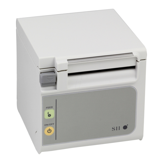
Page 13: Each Part Of Printer
3 EACH PART OF PRINTER Top paper discharge model 上面排紙モデル - 10 -... - Page 14 Front paper discharge model 前面排紙モデル 16 18 Ethernet model USB + Serial model Serial model シリアルモデル USB+シリアルモデル イーサネットモデル USB model USBモデル - 11 -...
- Page 15 (1) POWER switch (10) Paper width setting knob The POWER switch turns the printer ON or OFF. The knob to set the paper width. The LED lights when the printer turns ON. To It is set to 80 mm by default. When using paper turn the power OFF, hold down the switch for with 58 mm width, remove the coin screw, longer than three seconds.
- Page 16 LED Display LED (Lighting LED Indication LED (Color) Pattern) Power OFF Power ON (print-ready) Blue Printing Green Paper-near-end Blue Blink-1 Out-of-paper error Yellow Blink-1 Cover open error Yellow Hardware error Head temperature error Violet Vp voltage error Violet Blink-1 Cutter error Violet Blink-2 Rewriting external flash...
-
Page 17: Power Connection
4 POWER CONNECTION This printer can be powered with an AC adapter. Always refer to "15 SPECIFICATION" before using the AC adapter. ■ Connecting the AC Adapter (1) Connect the AC cable to the AC adapter. (2) Insert the DC jack of the AC adapter to the power connector of the printer. (3) Insert the AC plug of the AC cable to an electric outlet. -
Page 18: Thermal Paper Setting
5 THERMAL PAPER SETTING This printer uses the paper roll (hereinafter referred to as thermal paper). The function settings of the printer depend on the used thermal paper. See "9 FUNCTION SETTINGS", for details. ■ Thermal Paper Setting (1) Pull the release lever to open the paper cover. Top paper discharge model Front paper discharge model 上面排紙モデル... - Page 19 (4) Pull the thermal paper straight and then push the center of paper cover certainly to close it, to avoid one side lock defect. Top paper discharge model × ○ Front paper discharge model × ○ NOTE Pull the thermal paper straight. Push the paper cover certainly to avoid one side lock defect.
- Page 20 Recommended Thermal Paper Shape × × ○ NOTE DO NOT use deformed thermal paper. Doing so may cause the printer damaged. × ○ NOTE In case of using loosened paper roll, rewind the roll before using it. - 17 -...
-
Page 21: Adjustment Of Remaining Thermal Paper
6 ADJUSTMENT OF REMAINING THERMAL PAPER This printer detects remaining amount of the thermal paper by the paper-near-end sensor. Detecting the paper-near-end requires the replacement of the thermal paper with new one. ■ Removing Remaining Thermal Paper (1) Pull the release lever to open the paper cover. (2) Remove the thermal paper from the paper holder. - Page 22 [Top paper discharge model] 【上紙排出モデル】 Paper-near-end Paper-near-end ペーパニアエンド ペーパニアエンド B sensor setting lever A センサ設定レバー sensor センサ [Front paper discharge model] 【前紙排出モデル】 Paper-near-end Paper-near-end ペーパニアエンド ペーパニアエンド sensor setting lever C sensor センサ設定レバー センサ Paper-near-end Sensor Position Outside Diameter for Paper-near-end Detection φ22±2 mm in diameter (Top paper discharge model) φ25±2 mm in diameter (Top paper discharge model) φ22±2 mm in diameter (Front paper discharge model)
-
Page 23: Prevention And Treatment Of Paper Jam
7 PREVENTION AND TREATMENT OF PAPER JAM Do not touch the paper outlet during paper feeding or before paper cutting. Covering the paper outlet or pulling out the paper may cause a paper jam, a cut failure or carriage return malfunction. Never open the paper cover during paper cutting. - Page 24 ■ Cutter Error Treatment When the motor is locked during paper cutting due to a cutter error and the paper cover does not open, recover the printer according to the following procedure: (1) Turn the printer OFF. NOTE Be sure to turn the power off before handling a cutter error. (2) Pull the release lever repeatedly to retract the cutter blade.
-
Page 25: Test Print
8 TEST PRINT This printer has a test printing function. In test printing, the function settings of the printer and character strings for testing are printed. (1) Make sure that the thermal paper is set in the printer and the printer is turned off. If the thermal paper is not set, set the thermal paper as instructed in "5 THERMAL PAPER SETTING", and turn the printer OFF. -
Page 26: Function Settings
The function settings of the printer are stored in the FLASH memory. They are effective until rewriting them again. You can set these functions by using the Memory Switch (hereinafter referred to as MS) 1 to 7 and 13. See "RP-E10 SERIES THERMAL PRINTER TECHNICAL REFERENCE" for details. - 23 -... -
Page 27: Connecting To The Host Device
This printer supports the serial, USB, USB + serial, or Ethernet communication, depending on the model, through an interface cable. The function settings of the printer depend on the printer model and the communication method to be used. See "RP-E10 SERIES THERMAL PRINTER TECHNICAL REFERENCE". - Page 28 Ethernet interface cable NOTE When connecting an interface cable to the interface connector, push it until it clicks. DO NOT connect plugs of other cables including drawer kick cable or phone line to the interface connector. When connecting an outdoor aerial-wired LAN cable, be sure to use it through another anti-serge device.
-
Page 29: Connecting To The Drawer
■ Connecting to the Drawer (1) Turn the printer OFF. (2) Connect the plug of drawer kick cable to the drawer kick connector on the backside of the printer. (3) Turn the printer ON. NOTE When connecting or disconnecting the drawer kick cable, hold the plug and never pull the cable. -
Page 30: Settings When Using 58Mm Paper Width
Position B, and then fix it with the coin screw again. (4) Set the accompanying partition plate and the spacer plate to the position as shown in the figure. See "RP-E10 SERIES THERMAL PRINTER TECHNICAL REFERENCE" to set the paper width (MS2-6) to 58 mm. NOTE Set the paper width before using the printer for the first time. -
Page 31: Wall Mounting Kit (Wlk-B01-1)
12 WALL MOUNTING KIT (WLK-B01-1) The Wall Mounting Kit is exclusive for the Front paper discharge model. It cannot be used for the Top paper discharge model. (1) Preparation When you open the carton, make sure it contains the product and its accessories. Printer attachment screw (four プリンタ取り付けねじ 4本... - Page 32 (2) Installation of Printer Bracket Fix it with four attachment screws certainly as shown in the following figure. The tightening torque should be 39.2 cN•m (4 kgf•cm). NOTE Turn the printer OFF before installation. Remove the AC cable of the AC adapter and the interface cable. (3) Installation of Wall Hanging Bracket Fix the wall hanging bracket to the mounting surface, and then secure it with six attachment screws for the bracket.
- Page 33 (4) Installation of the Printer Slide the printer into the wall hanging bracket from the top to the bottom to insert the printer bracket into the wall hanging bracket, as shown in the figure. NOTE Check the place and the material/structure of the wall, and then install the printer securely.
-
Page 34: Printer Maintenance
13 PRINTER MAINTENANCE The thermal head of this printer does not require user maintenance. If paper powder accumulates, clean the thermal head to maintain maximum print quality for an extended period of time. ■ Cleaning Thermal Head/Platen Roller/Rubber Feet(Front Paper Discharge Model) (1) Turn the printer OFF. -
Page 35: Troubleshooting
14 TROUBLESHOOTING Check the following points before requesting for repair: ■ The power does not turn ON • Is specified AC adapter being used? • Are the AC cable and AC adapter connected correctly? • Is the AC adapter connected to the printer correctly? ■... -
Page 36: Specification
15 SPECIFICATION ■ Printer Specifications Item Specification Model RP-E10, RP-E11 Printing method Thermal Characters per line Paper width 80 mm: 24 dots x 12 dots 48 (42 ) 16 dots x 8 dots 72 (64 Paper width 58 mm: 24 dots x 12 dots 36 (30 ) 16 dots x 8 dots 54 (45 Character size One-byte: H24 dots x W12 dots, H16 dots x W8 dots... -
Page 37: Interface Specifications
■ Interface Specifications Serial interface specifications Item Specification Synchronous Asynchronous Baud rate 9600, 19200, 38400, 115200 bps Data length 7 or 8 bits Parity None, Even or Odd Data control Hardware control, Xon/Xoff USB interface specifications Item Specification Version Ver 2.0 conformity Printer data transmission mode Bulk transfer (12 Mbps) Ethernet interface specifications... - Page 38 ■ Compliance Table Check the list below to see if the printer and its accessories can be operated in destination countries and comply with the regulations. ○: Compliant PW-E2427-W1 Countries RP-E10 (Specified AC adapter) Japan ○ ○ ○ ○ Canada ○...
-
Page 39: Accessories And Consumable Parts
16 ACCESSORIES AND CONSUMABLE PARTS ■ Accessories Name Model Specified AC adapter PW-E2427-W1 Specified AC cable For Japan CB-JP03-20A For USA, Canada, Mexico CB-US03-20A For EU (except United Kingdom), EFTA, Russia CB-CE03-20A For United Kingdom CB-UK02-20A For Australia, New Zealand CB-AU02-20A Wall mounting kit WLK-B01-1... - Page 40 Seiko Instruments Inc. 1-8, Nakase, Mihama-ku, Chiba-shi, Chiba 261-8507, Japan Print System Division Telephone:+81-43-211-1106 Facsimile:+81-43-211-8037 Seiko Instruments USA Inc. Thermal Printer Div. 21221 S. Western Avenue, Suite 250, Torrance, CA 90501, USA Telephone:+1-310-517-7778 Facsimile:+1-310-517-7779 Seiko Instruments GmbH Siemensstrasse 9, D-63263 Neu-lsenburg, Germany Telephone:+49-6102-297-0 Facsimile:+49-6102-297-222 Seiko Instruments (H.K.) Ltd.
Need help?
Do you have a question about the RP-E10 Series and is the answer not in the manual?
Questions and answers
I am working in an office with a Thermal Printer SLP 620 SII. It's been set up but the previous employee never got a chance to show me on the computer how to use it. I have no idea where to search for it on the computer.