Advertisement
Quick Links
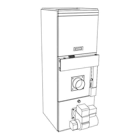
OIL FIRED FURNACE
DOWNFLOW or HORIZONTAL
INSTALLER / SERVICE TECHNICIAN:
USE THE INFORMATION IN THIS MANUAL FOR THE
INSTALLATION / SERVICING OF THE UNIT AND KEEP
THE DOCUMENT NEAR THE FURNACE FOR FUTURE
REFERENCE.
HOMEOWNER:
PLEASE KEEP THIS MANUAL NEAR THE FURNACE
FOR FUTURE REFERENCE.
Printed in Canada
Printed on 100% recycled paper
445 01 4024 05
Model:
OCF105A12C
Caution: Do not tamper with the
unit or its controls.
Call a qualified service technician.
Manufactured by:
UTC Canada Corporation
ICP DIVISION
3400 Industrial Boulevard
Sherbrooke, Quebec - Canada
J1L 1V8
2008/12/02
X40084 Rev. K
Advertisement

Subscribe to Our Youtube Channel
Related Manuals for ICP OCF105A12C


Summary of Contents for ICP OCF105A12C
- Page 1 OIL FIRED FURNACE DOWNFLOW or HORIZONTAL Model: OCF105A12C INSTALLER / SERVICE TECHNICIAN: Caution: Do not tamper with the unit or its controls. USE THE INFORMATION IN THIS MANUAL FOR THE Call a qualified service technician. INSTALLATION / SERVICING OF THE UNIT AND KEEP THE DOCUMENT NEAR THE FURNACE FOR FUTURE REFERENCE.
- Page 2 PART 1 INSTALLATION SAFETY CONSIDERATIONS 1.2) SAFE INSTALLATION REQUIREMENTS INSTALLATION OF OIL FIRED HEATING UNITS WARNING SHALL BE IN STRICT ACCORDANCE WITH THE REGULATIONS OF THE AUTHORITIES HAVING JURISDICTION. IN CANADA, CSA B139 AND IN THE Installation or repairs performed by unqualified UNITED STATES, NFPA NO.31-1992 INSTALLATION persons can result in hazards to them and others.
- Page 3 1.2.2) Freezing Temperatures and Your Structure Before servicing, allow furnace to cool down. Always shut off electricity and fuel to furnace when servicing. This will prevent electrical shock or burns; WARNING Seal supply and return air ducts; The vent system MUST be checked to determine that it is the correct type and size;...
- Page 4 TABLE 1 Minimum Installation clearances from combustible materials (Chimney installation*) RECOMMENDED ACCESS LOCATION APPLICATION OCF105 AND ODH53 FOR SERVICE Furnace 25.4 mm (1”) Sides Supply plenum, warm air duct within 6 ft of furnace 25.4 mm (1”) Back Furnace 25.4 mm (1”) Furnace casing or plenum 25.4 mm (1”) 0.6 m (24”)
- Page 5 •hr •°F / Btu): Without barometric damper R2 (2 ft Clay-lined masonry, A-vent •hr •°F / Btu): R3 (3 ft Metal liner in clay-lined Masonry •hr •°F / Btu): Due to the lack of dilution air that would ordinarily be drawn into the R6 (6 ft Metal or clay-lined masonry with R4.5 (4.5 barometric damper, the dew point of the flue gases is raised.
- Page 6 DV-2000™ – Vent terminal kits FIGURE 1 The certified standard vent terminal kit is Model No. VTK-1 for models ODH5-F and OCF105A12B and is suitable for installation in walls up to 0.3 m (14") thick. Both kits contain the following items to complete the hook-up to the venting and furnace: Description Terminal...
- Page 7 Side wall venting installation - DV-2000™ 11. Two stainless steel band clamps are provided in the VTK Series kits. Position one stainless steel band clamp over the gum seal joint so that the edge of the clamp closest to the breach lines up with the edge of the gum seal that is closest to the breach.
- Page 8 FIGURE 1.1 FIGURE 1.2 CUT OUTER SLEEVE THREAD SPIN SLEEVE BACK 5” ONTO OUTER SLEEVE FIGURE 1.3 FIGURE 1.4 THREAD SPIN SLEEVE BACK 10” CUT STAINLESS STEEL CORE BACK BY 3” FIGURE 1.5 FIGURE 1.6 INSERT STAINLESS STEEL DRIVE THREE STAINLESS STEEL CORE ONTO BREECH TUBE SCREWS, STARTING NEAR TOP 445 01 4024 05...
- Page 9 FIGURE 1.7 FIGURE 1.8 CORRECT BAND OVERLAP APPLY THE SEALANT TO THE TUBE END FIGURE 1.9 FIGURE 1.10 SEALANT FLOWING TWIST SPIN SLEEVE TIGHTLY INTO OUT FROM UNDER BREECH COLLAR BAND CLAMP AT BREECH SEALANT OUTFLOW FIGURE 1.11 SEALANT FLOWING OUT FROM UNDER BAND CLAMP AT TERMINAL SEALANT OUTFLOW 445 01 4024 05...
- Page 10 FIGURE 1.12 TWIST SPIN SLEEVE TIGHTLY INTO RECESS VENT TERMINAL PRESSURE SWITCH. REFER TO WIRING DIAGRAM FOR ELECTRICAL CONNECTION. FIGURE 1.13 FIGURE 1.14 INSTALL CAULK TO SEAL STABILIZER STABILIZER SHROUD TO THE WALL SHROUD 445 01 4024 05...
- Page 11 Installing terminal in the wall - DV-2000™ 1.5.1) General Cut a 152.4 mm (6") hole in the side-wall in accordance with the Oil furnaces must have an adequate supply of combustion air. It is location considerations outlined in the previous section; common practice to assume that older homes have sufficient Fasten the wall plate to the inside-wall using 4 field-provided infiltration to accommodate the combustion air requirement for the...
- Page 12 Outdoor combustion air kits – chimney venting If PVC fittings are mixed with ABS fittings, use solvent cement that is approved for bonding the two plastics. The following kit has been certified for use on this appliance. The kit contains an important safety feature, namely a vacuum relief valve, or Intake pipe length - DV-2000™...
- Page 13 10 (or less) micron filter in the fuel oil Place one prong on your grounded electric entry box and one line. ICP requires that this practice be followed in order prong on the black wire; to keep the lifetime heat exchanger warranty intact.
- Page 14 CAUTION CAUTION A positive pressure venting system (Sealed Combustion When ducting supplies air to a space other than where System or Direct Vent) MUST NOT use the BVSO. Follow the furnace is located, the return-air ducts must be the instructions supplied with the venting system. sealed and also be directed to the space other than where the furnace is located.
- Page 15 PART 2 OPERATION 2.1) MANUAL OPERATION SWITCHES After the pre-purge period, the solenoid valve opens, allowing oil to flow through the nozzle. At the same time, the burner motor FIGURE 3 ignition coil produces spark; The ignition transformer spark ignites the oil spray; Cad cell senses flame and burner continues to fire.
- Page 16 Abnormal operation Set thermostat higher than the room temperature; If the burner motor does not start or ignition fails, turn off the Start-up disconnect switch CALL QUALIFIED SERVICE TECHNICIAN. When the room thermostat calls for heat, the normally open contact W-R closes, the burner blower starts and creates suction in the intake piping circuit and pressure in the vent piping circuit;...
- Page 17 2.3.7) Overfire pressure test procedure 2.3.10) DV-2000™ Blocked intake / blocked vent test To read the pressure, replace the glass with the washer supplied with the appliance; On side-wall vented furnaces, the DV-2000™ venting system After the test, put the glass back in place in the sight glass incorporates a safety shutdown system that will shut the burner down assembly;...
- Page 18 PART 3 MAINTENANCE 3.1) GENERAL IMPORTANT Do not vacuum the ceramic chambers—they are easily Preventive Maintenance damaged. “Preventive maintenance” is the best way to avoid unnecessary expense and inconvenience. Have your heating system and burner inspected at regular intervals by a qualified service Soot will have collected in the first sections of the heat exchangers technician.
- Page 19 3.1.6) Air filters Pry the bottom half of the heat exchanger apart by using the designated prying tabs; Air filters are the disposable type. They should be replaced at least Remove the bottom half of the heat exchanger through the front once a year.
- Page 20 PART 4 INFORMATION Model: Serial number: Installation date of the furnace: Service telephone # - Day: Night: Dealer name and address: START-UP TEST RESULTS Nozzle: Pressure: lbpsi Burner adjustments: Primary air Fine air Drawer Assembly Smoke scale: (Bacharach) Gross stack temperature: °F Ambient temperature: °F...
-
Page 21: Technical Specifications
Blow er w heel size (in.) 10 X 10 Filter quantity and size (in.) (1) 20 X 20 TABLE 5 Air delivery - CFM with air filter ODH53F100LB-3MC, OCF105A12C EXTERNAL STATIC PRESSURE WITH AIR FILTER SPEED 0.1" 0.2" 0.3" 0.4"... - Page 22 FIGURE 5 Models: ODH53F100LB-3MC, OCF105A12C DNS-0589 Rev. C 445 01 4024 05...
- Page 23 FIGURE 6 Wiring diagram, ODH53F100LB-3MC, OCF105A12C 445 01 4024 05...
-
Page 24: Replacement Parts
COMPONENTS REPLACEMENT PARTS 445 01 4024 05... - Page 25 PARTS LIST Model : ODH53F100LB-3MC, OCF105A12C B50030A 445 01 4024 05...
- Page 26 PARTS LIST Model : ODH53F100LB-3MC, OCF105A12C ITEM DESCRIPTION PART # Complete heat exchanger B30776-01 Top heat exchanger B30542-01 Gasket, heat exchanger B30517 Hexagonal flange nut 3/8-16NC brass F07O001 Combustion chamber B30518 Bottom heat exchanger B30757 Gasket panel, peep hole B30753...
Need help?
Do you have a question about the OCF105A12C and is the answer not in the manual?
Questions and answers