Advertisement
OIL FIRED FURNACE
INSTALLER / SERVICE TECHNICIAN:
USE THE INFORMATION IN THIS MANUAL FOR THE
INSTALLATION AND SERVICING OF THE UNIT. KEEP THE
DOCUMENT
NEAR
REFERENCE.
HOMEOWNER:
PLEASE KEEP THIS MANUAL NEAR THE FURNACE FOR
FUTURE REFERENCE.
Printed in Canada
Printed on 100% recycled paper
UPFLOW
THE
FURNACE
445 01 4054 06
Caution: Do not tamper with
the unit or its controls.
Call a qualified service
technician.
FOR
FUTURE
Manufactured by:
UTC Canada Corporation
ICP Division
3400 Industrial Boulevard
Sherbrooke, Quebec - Canada
J1L 1V8
2008-08-11
Models :
FLO115DABR-C
LBO125DABR13-D
LBO145DABR34-D
MBO115DABR-D
MBOV115DABR-D
OLF140C12C
OLR182A16C
X40054 Rev. X
Advertisement
Table of Contents

Related Manuals for ICP FLO115DABR-C


Summary of Contents for ICP FLO115DABR-C
- Page 1 OIL FIRED FURNACE UPFLOW Models : FLO115DABR-C LBO125DABR13-D LBO145DABR34-D MBO115DABR-D MBOV115DABR-D OLF140C12C OLR182A16C Caution: Do not tamper with INSTALLER / SERVICE TECHNICIAN: the unit or its controls. USE THE INFORMATION IN THIS MANUAL FOR THE Call a qualified service INSTALLATION AND SERVICING OF THE UNIT. KEEP THE technician.
-
Page 2: Part 1 Installation
PART 1 INSTALLATION 1.2) SAFE INSTALLATION REQUIREMENTS SAFETY CONSIDERATIONS INSTALLATION OF OIL FIRED HEATING UNITS WARNING SHALL BE IN STRICT ACCORDANCE WITH THE REGULATIONS OF THE AUTHORITIES HAVING JURISDICTION. IN CANADA CSA B139 AND IN THE Installation or repairs performed by unqualified UNITED STATES NFPA NO.31-1992 INSTALLATION persons can result in hazards to them and others. -
Page 3: Positioning The Furnace
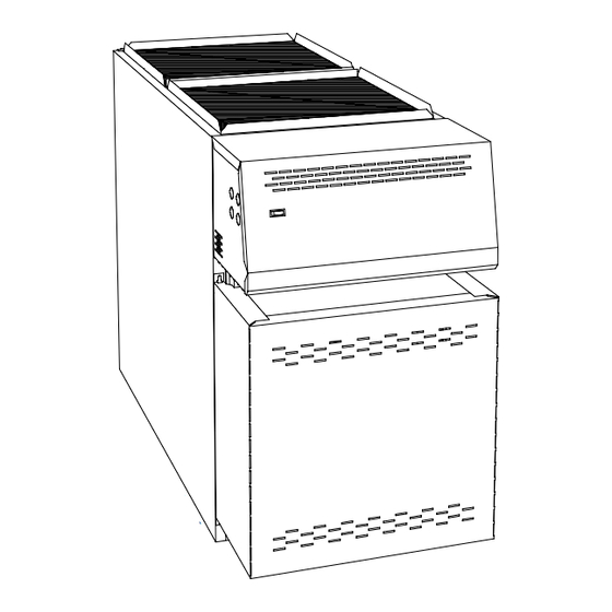
1.2.2) Freezing temperatures and your building Follow a regular service and maintenance schedule for the most efficient and safe operation of the furnace. WARNING Before servicing, allow furnace to cool. Always shut off electricity and fuel to the furnace when servicing. This will prevent electrical shock or burns;... - Page 4 1.3.1) Installation of the filter rack 1.4) VENTING When you install your furnace, the filter rack opening can be installed WARNING on either side (right or left) for air filter maintenance. Poisonous carbon monoxide gas, fire FIGURE 1 explosion hazard. Read and follow all instructions in this section.
-
Page 5: Air For Combustion
NOTE: Thermal resistance values for typical chimneys are as 1.5) AIR FOR COMBUSTION follows: WARNING •hr •°F / Btu): R2 (2 ft Clay-lined masonry, "A" vent •hr •°F / Btu): R3 (3 ft Metal liner in clay-lined masonry Poisonous carbon monoxide gas hazard. •hr •°F / Btu): R6 (6 ft Metal or clay-lined masonry with R4.5... -
Page 6: Burner Installation
Exposure to these substances: Follow the pump instructions to determine the size of tubing you need in relation to the rise, or to the horizontal distance. Permanent wave chemicals for hair; Inspect the entire oil distribution system for leaks at the beginning of Chlorinated waxes and cleaners;... -
Page 7: Installing Accessories
Installation Code for oil burning equipment requires the death, property damage. installation of a 10 micron (or finer) filter in the fuel oil line. ICP requires that this practice be followed in order to keep the lifetime heat exchanger warranty intact. 445 01 4054 06... - Page 8 1.9.1) Air conditioning WARNING An air conditioning coil may be installed on the supply air side only. Also, notwithstanding the evaporator coil manufacturer’s instructions, Poisonous carbon monoxide gas hazard. a minimum clearance of 15 cm (6") must be allowed between the bottom of the coil drain pan, and the top of the heat exchanger.
-
Page 9: Part 2 Operation
PART 2 OPERATION 2.1) SEQUENCE OF OPERATION CAUTION Do not attempt to start the burner when excess oil has 2.1.1) Sequence of operation accumulated, when the furnace is full of vapour, or Beckett AFG, Riello 40-F and Aero F-FAC when the combustion chamber is very hot. Normally open contact (T-T) on primary relay closed when thermostat calls for heat;... - Page 10 2.2.7) Vent temperature test FIGURE 3 Place a thermometer in the test hole located in the breech pipe. The vent temperature should be between 204°C to 302°C (400°F to 575°F). If not, check for improper air temperature rise, pump pressure, nozzle size, or for a badly sooted heat exchanger.
-
Page 11: Part 3 Maintenance
PART 3 MAINTENANCE Soot will have collected in the first sections of the heat exchangers 3.1) GENERAL only if the burner was started after the combustion chamber was flooded with fuel oil, or if the burner has been operating in a severely Preventive Maintenance contaminated condition. - Page 12 3.1.3) BLOCKED VENT SHUT-OFF (BVSO) 3.1.6) Oil filter CLEANING Tank filter The tank filter should be replaced as required. For continued safe operation, the Blocked Vent Shut-Off System (BVSO) is required to be inspected and maintained annually by a qualified agency. Secondary filter The 10 micron (or less) filter cartridges should be replaced annually.
- Page 13 PART 4 INFORMATION Model: Serial number: Furnace installation date: Service telephone # - Day: Night: Dealer name and address: START-UP TEST RESULTS Nozzle: Pressure: Lb/psi Burner adjustments: Primary air Fine air Draw Assembly Smoke scale: (Bacharach) Gross stack temperature: °F Ambient temperature: °F Chimney draft:...
- Page 14 TABLE 3.1 Technical specifications, MBO115DABR-D & MBOV115DABR-D RATING AND PERFORMANCE Firing rate USGPH 0.65 0.75 0.85 0.90 Input (BTU/h) 91,000 105,000 119,000 126,000 Heating capacity (BTU/h) 74,000 85,000 97,000 103,000 Maximum temperature rise 13°C - 29°C (55 - 85°F) BECKETT BURNER (3450 RPM) AFG-F3 (TUBE INSERTION 5 3/16") Low firing rate baffle Static disc, model...
- Page 15 TABLE 3.2 Technical specifications, LBO125DABR13-D (BECKETT, RIELLO AND AERO BURNERS) RATING AND PERFORMANCE Firing rate USGPH 0.75 0.85 1.00 1.10 Input (BTU/h) 105,000 119,000 140,000 154,000 Heating capacity (BTU/h) 84,525 95,795 112,700 123,970 Maximum temperature rise 13°C - 29°C (55 - 85°F) BECKETT BURNER (3450 RPM) AFG-F3 (TUBE INSERTION 5 3/16") Low firing rate baffle...
- Page 16 TABLE 3.3 Technical specifications, LBO145DABR34-D and OLR182A16C (BECKETT, RIELLO AND AERO BURNERS) RATING AND PERFORMANCE Firing rate USGPH 1.00 1.10 1.20 1.25 1.30 Input (BTU/h) 140,000 154,000 168,000 175,000 182,000 Heating capacity (BTU/h) 112,700 123,970 135,240 140,875 146,510 Maximum temperature rise 13°C - 29°C (55 - 85°F) BECKETT BURNER (3450 RPM) AFG-F3 (Tube insertion 5-3/16")
- Page 17 TABLE 3.4 Technical specifications, FLO115DABR-C and OLF140C12C (BECKETT, RIELLO AND AERO BURNERS) RATING AND PERFORNACE Firing rate USGPH 0.75 0.85 1.00 Input (BTU/h) 105,000 119,000 140,000 Heating capacity (BTU/h) 84,525 95,795 112,700 Maximum heating temperature rise 13°C - 29°C (55 - 85 Degr.F) BURNER BECKETT (3450 RPM) AFG-F3 (TUBE INSERTION 5 3/16")
- Page 18 FIGURE 4.1 Model: MBO115DABR-D DNS-0590 Rev. D FIGURE 4.2 Model: MBOV115DABR-D DNS-0596 Rev. D 445 01 4054 06...
- Page 19 FIGURE 4.3 Models: LBO125DABR13-D, LBO145DABR34-D & OLR182A16C DNS-0576 Rev. F FIGURE 4.4 Model: FLO115DABR-C & OLF140C12C DNS-0666 Rev. C 445 01 4054 06...
- Page 20 FIGURE 5 Wiring diagram, MBO115DABR-D, MBOV115DABR-D, LBO125DABR13-D, LBO145DABR34-D & OLR182A16C, FLO115DABR-C & OLF140C12C DNS-1014 Rev. A 445 01 4054 06...
- Page 21 PARTS LIST Model: MBO115DABR-D B50040B 445 01 4054 06...
- Page 22 PARTS LIST Model: MBO115DABR-D ITEM PART # DESCRIPTION COMMENTS B40119-01 Complete heat exchanger Item 16 included; item 38 not included B40067 Top baffle B40466-01 Electrical box cover assembly Wiring diagram label included B02282 Observation door B40048 Burner panel assembly Items 4 and 9 included F06F005 Washer 3/8"...
- Page 23 PARTS LIST Model: MBOV115DABR-D 445 01 4054 06 B50041B...
- Page 24 PARTS LIST Model: MBOV115DABR-D ITEM PART # DESCRIPTION COMMENTS B40119-01 Complete heat exchanger Item 24 included; item 46 not included B40067 Top baffle R02I007 Fan Limit Control L6064A B40460 Component panel Items 5, 6 and 7 not included L01H009 Relay SPDT 24 VAC L05F009 Terminal strip, 4 positions L01F009...
- Page 25 PARTS LIST Model: LBO125DABR13-D 445 01 4054 06 B50038C...
- Page 26 PARTS LIST Model: LBO125DABR13-D ITEM PART # DESCRIPTION COMMENTS B40117-01 Complete heat exchanger Item 20 included; item 41 not included B40067 Top baffle B40466-01 Electrical box cover assembly "Electrical Diagram" label included B02282 Observation door B40048 Burner panel assembly Items 4 and 9 included F07O001 Hexagonal flange nut 3/8-16NC brass 18 required...
- Page 27 PARTS LIST Models: LBO145DABR34-D & OLR182A16C 445 01 4054 06 B50039F...
- Page 28 PARTS LIST Models: LBO145DABR34-D & OLR182A16C ITEM PART # DESCRIPTION COMMENTS B40118-01 Complete heat exchanger Item 19 included; item 35 not included B40067 Top baffle B40466-01 Electrical box cover assembly Wiring diagram label included B02282 Observation door B40048 Burner panel assembly Items 4 and 9 included F07O001 Hexagonal flange nut ⅜-16NC brass...
- Page 29 PARTS LIST Model: FLO115DABR-C & OLF140C12C 445 01 4054 06 B50042A...
- Page 30 PARTS LIST Model: FLO115DABR-C & OLF140C12C ITEM PART # DESCRIPTION COMMENTS B40385 Heat exchanger Combustion chamber included B40358 Side deflector 2 required B40360 Gasket, smoke outlet L07F003 Rocker switch SPST B40491 Electrical box Box only L05F009 Single terminal strip L01H009...
Need help?
Do you have a question about the FLO115DABR-C and is the answer not in the manual?
Questions and answers