Advertisement
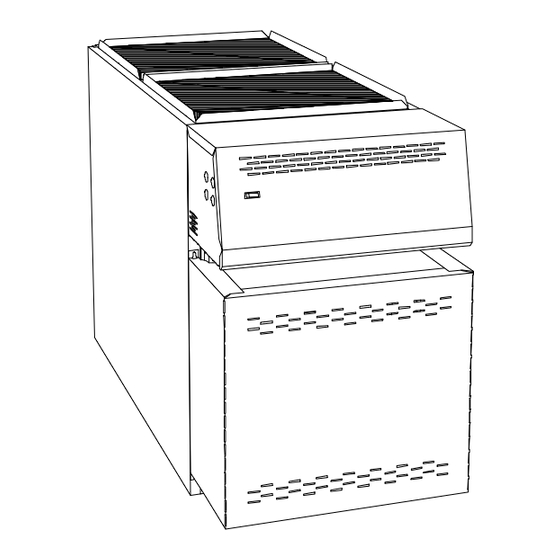
UPFLOW WARM AIR
Save these instructions for future reference.
Printed in Canada
FURNACE
Models:
FLO115DABR-A
LBO125DABR13-B
LBO145DABR12-B
LBO145DABR34-B
MBO115DABR-B
MBOV115DABR-B
MBOV115DABRU-B
MBOV115DBU-C
OLF140C12A
OLR182A16A
Manufactured by:
International Comfort Products
(Division of U.T.C. Canada)
3400 Blvd Industriel Sherbrooke PQ Canada
Caution : Do not tamper with
the unit or its controls.
Call a qualified service
technician.
2001/08/10
X40054 Rev. H
445 02 4054 01
Advertisement
Table of Contents

Related Manuals for ICP FLO115DABR-A


Summary of Contents for ICP FLO115DABR-A
- Page 1 Models: FLO115DABR-A LBO125DABR13-B LBO145DABR12-B LBO145DABR34-B MBO115DABR-B MBOV115DABR-B MBOV115DABRU-B MBOV115DBU-C OLF140C12A OLR182A16A Manufactured by: International Comfort Products (Division of U.T.C. Canada) 3400 Blvd Industriel Sherbrooke PQ Canada UPFLOW WARM AIR Caution : Do not tamper with FURNACE the unit or its controls.
-
Page 2: Part 1 Installation
PART 1 INSTALLATION SAFE INSTALLATION REQUIREMENTS SAFETY CONSIDERATIONS INSTALLATION OF OIL FIRED HEATING UNITS WARNING WARNING SHALL ACCORDANCE WITH REGULATION AUTHORITIES HAVING JURISDICTION, IN CANADA THE CSA B139 OR IN Installation or repairs made by unqualified persons UNITED STATES NFPA NO.31-1992 can result in hazards to you and others. -
Page 3: Locating The Furnace
Before servicing, allow furnace to cool. Always shut off electricity 2.2) Freezing Temperature and Your and fuel to furnace when servicing. This will prevent electrical Structure: shock or burns. Seal supply and return air ducts. The vent system MUST be checked to determine that it is the WARNING WARNING correct type and size. - Page 4 WARNING WARNING The required minimum clearances for this furnace are specified in table #1. The furnace should be located as close as possible to the chimney to Electrical shock hazard. keep vent connections short and direct. The furnace should also be located as near as possible to the center of the air distribution system.
-
Page 5: Air For Combustion
Applying the Table: The minimum size permitted shall be 4 in. inside diameter. If a furnace with 0.60 USGPH nozzle is to be connected to a 20 ft. tall The maximum size permitted shall be 5 in. inside diameter. clay-lined masonry chimney, the thermal resistance of this chimney type is R2, which is less than R6. -
Page 6: Oil Tanks And Lines
10 micron (or less) filter in the fuel oil CAUTION line. ICP requires that this practice be followed in order Do not turn on the burner until you have checked the to keep the lifetime heat exchanger warranty intact. -
Page 7: Installing Accessories
8.4) Ductwork and Filter: NOTE: You may notice a slight odor the first time your furnace is operated. This will soon disappear. It is only the oil used on the parts during manufacturing. Installation: Design and install air distribution system to comply with Air Conditioning Contractors of America manuals or other approved INSTALLING ACCESSORIES methods that conform to local codes and good trade practices. -
Page 8: Part 2 Operation
PART 2 OPERATION SEQUENCE OF OPERATION bleed screw - the oil should flow absolutely free of white streaks or bubbles to indicate that no air is being drawn into the suction side of the oil piping and pump. Tighten the bleed screw and the burner will fire. -
Page 9: Part 3 Maintenance
The temperature rise is calculated by subtracting the return air 2.7) Fan limit adjustment: temperature from the supply air temperature. FIGURE # 2 If the temperature rise exceeds the temperature specified in table # 3.1 to # 3.5, change to the next higher blower speed tap until the temperature rise falls to at this temperature or below. - Page 10 Do not tamper with the unit or controls. Call your service If the pot is damaged, it must be replaced. A damaged pot could lead technician. to premature heat exchanger failure. Cracking of the fire pot is normal, however, replace the pot if the cracks have propagated more than 2/3 Before calling for service, check the following.
- Page 11 Gradually block off the intake. The CO2 should increase by a horizontal position. Also, check that the counterweight has been maximum of 0.5 percentage points at the fully blocked condition. If not, properly adjusted in accordance with the CAS-2B installation check that the VRV gate is pivoting freely and that the pivot rod is in a instructions.
- Page 12 TABLE # 3.1 Technical specifications, MBO115DABR-B, MBOV115DABR-B, MBOV115DABRU-B & MBOV115DBU-C RATING AND PERFORNACE Firing rate USGPH 0.65 0.75 0.85 0.90 Input (BTU/h) 91 000 105 000 119 000 126 000 Heating capacity (BTU/h) 74 000 85 000 97 000 103 000 Maximum heating temperature rise (degr.F) 55 - 85 Degr.F BURNER BECKETT (3450 RPM)
- Page 13 TABLE # 3.2 Technical specifications, LBO125DABR13-B (BECKETT, RIELLO AND AERO BURNER) RATING AND PERFORMANCE Firing rate USGPH 0.75 0.85 1.00 1.10 Input (BTU/h) 105 000 119 000 140 000 154 000 Heating capacity (BTU/h) 84 525 95 795 112 700 123 970 Maximum heating temperature rise (degr.F) 55 - 85 Degr.F...
- Page 14 TABLE # 3.3 Technical specifications, LBO145DABR12-B (BECKETT, RIELLO AND AERO BURNER) RATING AND PERFORNACE Firing rate USGPH 1.00 1.10 1.20 1.25 1.30 Input (BTU/h) 140 000 154 000 168 000 175 000 182 000 Heating capacity (BTU/h) 112 700 123 970 135 240 140 875 146 510...
- Page 15 TABLE # 3.4 Technical specifications, LBO145DABR34-B and OLR182A16A (BECKETT, RIELLO AND AERO BURNER) RATING AND PERFORNACE Firing rate USGPH 1.00 1.10 1.20 1.25 1.30 Input (BTU/h) 140 000 154 000 168 000 175 000 182 000 Heating capacity (BTU/h) 112 700 123 970 135 240 140 875...
- Page 16 TABLE # 3.5 Technical specifications, FLO115DABR-A and OLF140C12A (BECKETT, RIELLO AND AERO BURNER) RATING AND PERFORNACE Firing rate USGPH 0.75 0.85 1.00 Input (BTU/h) 105 000 119 000 140 000 Heating capacity (BTU/h) 85 000 97 000 114 000 Maximum heating temperature rise (degr.F) 55 - 85 Degr.F...
- Page 17 FIGURE # 3.1 Model: MBO115DABR-B DNS-0590 Rev. D FIGURE # 3.2 Models: MBOV115DABR-B, MBOV115DABRU-B & MBOV115DBU-C DNS-0596 Rev. D...
- Page 18 FIGURE # 3.3 Models : LBO125DABR13-B, LBO145DABR12-B, LBO145DABR34-B & OLR182A16A DNS-0576 Rev. D FIGURE # 3.4 Model : FLO115DABR-A & OLF140C12A DNS-0666 Rev. B...
- Page 19 FIGURE # 4.1 Wiring diagram, MBO115DABR-B, MBOV115DABR-B, LBO125DABR13-B, LBO145DABR12-B, LBO145DABR34-B & OLR182A16A DNS-0578 Rev. D...
- Page 20 FIGURE # 4.2 Wiring diagram, MBOV115DABRU-B & MBOV115DBU-C DNS-0593 Rev. B...
- Page 21 FIGURE # 4.3 Wiring diagram, FLO115DABR-A & OLF140C12A DNS-0658 Rev. B...
- Page 22 PART LIST Model : MBO115DABR-B DNS-0597 Rev. E...
- Page 23 PART LIST Model : MBO115DABR-B ITEM DESCRIPTION NUMBER COMMENTS Complete heat exchanger Item 16 included and item 38 not included B40119-01 Top baffle B40067 Electrical box cover ass'y Wiring diagram label included B40110 Observation door B00403 Burner panel ass'y B40048 Items 4 &...
- Page 24 PART LIST Model : MBOV115DABR-B DNS-0598 Rev. D...
-
Page 25: Part List
PART LIST Model : MBOV115DABR-B ITEM DESCRIPTION NUMBER COMMENTS Complete heat exchanger Item 24 included and item 46 not included B40119-01 Top baffle B40067 Fan limit control R02I006 Composant panel Items 5 & 6 not included B40137 Relay SPDT 120VAC Quantity required per unit: 2 L01H011 Terminal strip, 6 positions... - Page 26 PART LIST Models : MBOV115DABRU-B & MBOV115DBU-C DNS-0605 Rev. D...
- Page 27 PART LIST Models : MBOV115DABRU-B & MBOV115DBU-C ITEM DESCRIPTION NUMBER COMMENTS Complete heat exchanger B40119-01 Item 30 included and item 54 not included Top baffle B40067 Fan limit control R02I006 Composant panel Items 5 and 12 not included B40137 Relay SPDT 120VAC L01H011 Quantity required per unit: 2 Bushing 7/8"...
- Page 28 PART LIST Model : LBO125DABR13-B DNS-0585 Rev. D...
- Page 29 PART LIST Model : LBO125DABR13-B ITEM DESCRIPTION NUMBER COMMENTS Complet heat exchanger Item 20 included and item 41 not included B40117-01 Top baffle B40067 Electrical box cover ass'y Label "electrical diagram" included B40110 Observation door B02282 Burner panel ass'y Items 4 and 9 included B40048 Hexagonal flange nut 3/8-16NC brass Quantity: 18...
- Page 30 PART LIST Models : LBO145DABR12-B, LBO145DABR34-B & OLR182A16A DNS-0586 Rev. B...
- Page 31 PART LIST Models : LBO145DABR12-B, LBO145DABR34-B & OLR182A16A ITEM DESCRIPTION NUMBER COMMENTS Complet heat exchanger Item 19 included. Item 35 not included B40118-01 Top baffle B40067 Electrical box cover ass'y Electrical diagram label included B40110 Observation door B00403 Burner panel ass'y Items 4 and 9 included B40048 Hexagonal flange nut 3/8-16NC brass...
- Page 32 PART LIST Model : FLO115DABR-A & OLF140C12A DNS-0663 Rev. C...
- Page 33 PART LIST Model : FLO115DABR-A & OLF140C12A ITEM DESCRIPTION NUMBER COMMENTS Paper filter 20 x 20 x 1 Z04F004 Blower door B40381 Top back panel B40356 Paper filter 10 x 20 x 1 Z04F001 Fan limit control 5" R02I006 Plenum divider...
Need help?
Do you have a question about the FLO115DABR-A and is the answer not in the manual?
Questions and answers