Table of Contents
Advertisement
OIL
LO|BOY
DNS
1 61 RevA
INSTALLER / SERVICE TECHNICIAN:
USE
THE
INFORMATION
IN THIS
MANUAL
FOR THE
INSTALLATION
/ SERVICING OF THE FURNACE AND KEEP
THE
DOCUMENT
NEAR
THE
UNIT
FOR
FUTURE
REFERENCE.
HOMEOWNER:
PLEASE KEEP THIS MANUAL NEAR THE FURNACE FOR
FUTURE REFERENCE.
MODEL:
AMT098SDMA
AMT098SVMA
OLR098A12A
OLV098A12A
®
c
us
Attention:
Do not tamper with the unit or its
controls. Call a qualified service
technician.
Manufactured
by:
UTC Canada Corporation
ICP Division
3400 Industrial Boulevard
Sherbrooke,
Quebec - Canada
J1L 1V8
Printed in Canada
Printed on 100% recycled paper
2008-05-08
X40153 Rev. A
445 01 4040 00
Advertisement
Table of Contents

Related Manuals for ICP AMT098SDMA


Summary of Contents for ICP AMT098SDMA
- Page 1 Call a qualified service DOCUMENT NEAR UNIT FUTURE technician. REFERENCE. Manufactured HOMEOWNER: UTC Canada Corporation ICP Division PLEASE KEEP THIS MANUAL NEAR THE FURNACE FOR 3400 Industrial Boulevard FUTURE REFERENCE. Sherbrooke, Quebec - Canada J1L 1V8 Printed in Canada 2008-05-08 X40153 Rev. A...
-
Page 2: Table Of Contents
TABLE OF CONTENTS SAFETY REGULATIONS ............... SAFETY LABELING AND WARNING SIGNS ............IMPORTANT INFORMATION ................DETECTION SYSTEMS ..................DANGER OF FREEZING ..................INSTALLATION ..................POSITIONING THE FURNACE ................ELECTRICAL SYSTEM 3 & 4) ..............(FIGURES INSTALLATION OF THE THERMOSTAT ............... INSTALLATION OF THE BURNER ................ -
Page 3: Safety Regulations
Before calling for service, be sure to have the SAFETY REGULATIONS information page of your manual close by in order be able to provide the contractor with the SAFETY LABELING required information, such as the model and serial WARNING SIGNS numbers of the furnace. -
Page 4: Installation
INSTALLATION 2.1.1 Installation in an enclosure The unit is shipped with a burner and its controls. It requires a The unit can be installed in an enclosure such as a closet. 115VAC power supply to the control panel and thermostat hook-up as shown on the wiring diagram, one or more oil line However, ventilation... -
Page 5: Installation Of The Thermostat
INSTALLATION OF THE THERMOSTAT Note: On units with 2 stage compressors, terminal Y1 must be used. When Y1 on the electronic control receives A thermostat must be installed to control the temperature a 24 VAC signal, the air flow is reduced by 55%. Do not the area to be heated. -
Page 6: Blocked Vent Shut-Off Device (Bvso) For Chimney Venting
Refer to the detailed instructions and wiring diagrams supplied with the BVSO for the installation and wiring procedures. The length of wires supplied with the unit is Poisonous carbon monoxide gas hazard. such that the safety device must be installed between the flue outlet of the appliance and the draft regulator, as Never install a hand operated... -
Page 7: Oil Tank
2.7.1 Contaminated Combustion A manual shut-off valve and an oil filter shall be installed Installations in certain areas or types of structures will increase in sequence from tank to burner. Be sure that the oil line is the exposure to chemicals or halogens that may harm the clean before connecting to the burner. -
Page 8: Supply Air Adjustments (Ecm Variable Speed Motors)
BLOWER SPEED ADJUSTMENTS AIR CONDITIONING MODE (A/C MODE, 4 SPEED MOTOR) SW2 - COOL Output A/C CAPACITY RECOMMENDED DIP Switch Positions Tons I POSITION (TONS) BLOWER SPEED MED-LOW MED-HIGH HIGH To effect the adjustment, the RED and BLUE wires can be CFM ADJUSTMENTS - ALL MODES changed on the motor. -
Page 9: Operation
2.12.3 Air Conditioner (or Heat Pump) OPERATING SEQUENCE OIL HEATING MODE An air conditioning coil may be installed on the supply air side ONLY. The W-R contact closes; burner motor starts pre-purge combustion chamber period of 10 to 15 seconds. During that time a spark is established Poisonous carbon monoxide gas hazard. - Page 10 IMPORTANT 3.3.7 Supply Air Temperature Rise Test The combustion check verification MUST be performed after Operate the burner for at least 10 minutes; the nozzle replacement or the burner cleaning, After these manipulations, the combustion 3arameters necessarily Measure the air temperature in the return air plenum;...
-
Page 11: Maintenance
CLEANING THE BLOCKED VENT MAINTENANCE SHUT-OFF DEVICE (BVSO) For continuous safe operation, the Blocked Vent Shut-off device (BVSO) must be inspected and maintained annually by a qualified service technician. I Electrical shock hazard. Disconnect power to the appliance; Turn OFF power and fuel to the furnace before... -
Page 12: Furnace Information
FURNACE INFORMATION Model: Serial number: Furnace installation date: Service telephone #-Day: Night: Dealer name and address: START-UP RESULTS Nozzle: Pressure: Ib/po 2 Burner adjustments: Primary air Fine air Drawer Assembly Smoke scale: CO2 : (Bacharach) Gross stack temperature: Ambient temperature: "... - Page 13 Table 1 Technical Specifications _ODEL AMT098 / OLR098 / OLV098 UNITS WITH 1/3 HP PSC MOTOR UNI'IS VVITH 1/2 HP ECM MOTOR F_,ATi_D_ =idng rate (USGDH) * 0.55 0.70 0.55 0.70 nput (BTU/h)* 77 000 98 000 77 000 98 000 V]a;4mum Heating capacity, (BTU!h)* 66 000...
- Page 14 Table 2 Airflow Data, Models with 1/2HP ECM motors OIL HEATING MODE 24 VAC input (R) on W only SW1- HEAT CFM with SW3-ADJ CFM with SW3-ADJ CFM with SW3-ADJ HEAT INPUT DIP switch position DIP switch position A DIP switch position B DIP switch position C (USGPH) 1260...
- Page 15 Table 3 Airflow Data, Models with ½ HP PSC motors AMT098 SPEED EXTERNAL STATIC PRESSURE WITH_R FILTER 0.2" (W.C.) 0.3" (W.C.) 0.4" (W.C.) 0.5" (W.C.) 0.6" (W.C.) 0.7" (W.C.) HIGH 1420 1335 1240 1180 1085 1025 MED-HIGH 1275 1230 1170 1095 1045 MED-LOW...
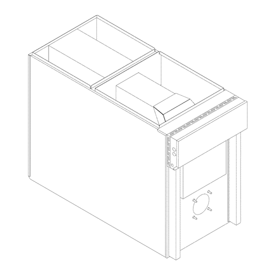
- Page 16 Figure 2 Furnace dimensions AMT098SDMA, AMT098SVMA, OLR098A12A, OLV098A12A i[il i[]l }@il i[}l }[iiil 2 Li ii]l iN[il iLll 1i68 R_,vA 445 01 4040 O0...
- Page 17 Figure 3 Wiring Diagram 4-Speed Motor (PSC) ........................................i oo 445 01 4040 O0...
- Page 18 Figure 4 Wiring Diagram Variable Speed Motor (ECM) • ÷[,i ° ....i-4 ../, zi. iziz .:oo ..7 .._:-d< x r_<i ........v,/,¢,{ ............,../_-.. :_ , ,> ......... !.._x/_ ( ..{ _h ..{ i....
- Page 19 COMPONENTS REPLACEMEN PARTS 445 01 4040 O0...
- Page 20 PARTS LIST AMT098SDMA, OLR098A12A With 4-speed motor PSC B50082A 445 01 4040 O0...
- Page 21 PARTS LIST AMT098SDMA, OLR098A12A With4-speedmotorPSC !TEM PART# DESCRIPTION COM i ENTS B03540 HEAT EXCHANGER ASSEMBLY Heat exchanger only J06L002 EXTRUDED JOINT 1/4 X 1/8 X25' B03570 FLOOR ASSEMBLY B03561 INSIDE WIRE CHANEL B03572 LOWER DIVIDER ASSEMBLY Includes panel, 3 gaskets baffle B03335-02 INT.
- Page 22 PARTS LIST AMT098SVMA, OLV098A12A With variable speed motor ECM /!'i , /, B50083A 445 01 4040 O0...
- Page 23 PARTS LIST AMT098SVMA, OLV098A12A WithvariablespeedmotorECM ITEM PART# I DES CRIp _ !ON CO Mi ENTS B03540 HEAT EXCHANGER ASSEMBLY Heat exchanger only J06L002 EXTRUDED JOINT 1/4 X 1/8 X25' B03570 FLOOR ASSEMBLY B03561 INSIDE WIRE CHANEL B03572 LOWER DIVIDER ASSEMBLY Includes panel, 3 gaskets and baffle...
Need help?
Do you have a question about the AMT098SDMA and is the answer not in the manual?
Questions and answers