Table of Contents
Advertisement
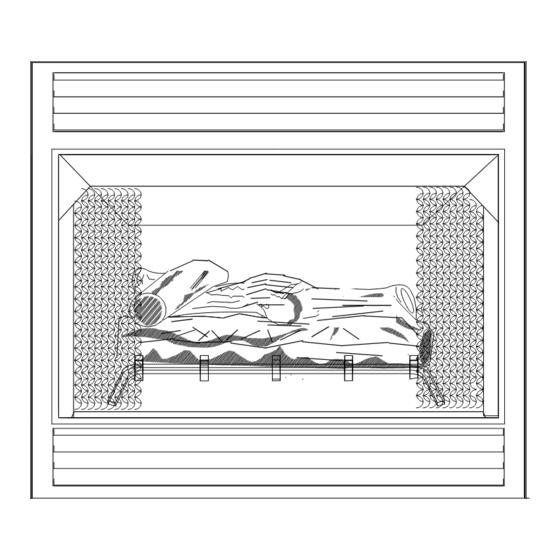
MAY BE INSTALLED AS A ZERO CLEARANCE FIREPLACE
OR WITH AN OPTIONAL WOODEN SURROUND
WARNING: If the information in this manual is not followed exactly, a fire or
explosion may result causing property damage, personal injury or loss of life.
−
Do not store or use gasoline or other flammable vapors and liquids in the vicinity of this
or any other appliance.
WHAT TO DO IF YOU SMELL GAS
•
Do not try to light any appliance.
• Do not touch any electrical switch; do not use any phone in your building.
• Immediately call your gas supplier from a neighbor's phone. Follow the gas supplier's
instructions.
• If you cannot reach your gas supplier, call the fire department.
−
Installation and service must be performed by a qualified installer, service agency or the
gas supplier.
This is an unvented gas-fired heater. It uses air (oxygen) from the room in which it is in-
stalled. Provisions for adequate combustion and ventilation air must be provided. Refer to
section " Producing Adequate Air For Combustion And Ventilation" page 11.
This appliance may be installed in an aftermarket, permanently located, manufactured
(mobile) home, where not prohibited by local codes.
This appliance is only for use with the type of gas indicated on the rating plate. This appli-
ance is not convertible for use with other gases.
INSTALLER: Leave this manual with the appliance.
CONSUMER: Retain this manual for future reference.
MANUFACTURED BY NEW BUCK CORPORATION
200 ETHAN ALLEN DRIVE,
SPRUCE PINE, N.C. 28777
www.buckstove.com
MODEL 36
This appliance is intended for supplemental heating.
VENT-FREE
Revised January 2013
Advertisement
Table of Contents

Related Manuals for BuckMaster 36


Summary of Contents for BuckMaster 36
- Page 1 MODEL 36 MAY BE INSTALLED AS A ZERO CLEARANCE FIREPLACE OR WITH AN OPTIONAL WOODEN SURROUND VENT-FREE WARNING: If the information in this manual is not followed exactly, a fire or explosion may result causing property damage, personal injury or loss of life.
-
Page 3: Table Of Contents
TABLE OF CONTENTS Safety Information Warnings ......................1 Installation (ZC)(WS) ........................4 Fireplace and Framing Dimensions (ZC) ..................5 Fireplace Clearances (ZC) ......................6 Finishing Your Fireplace (ZC) ...................... 7 Mantel Profiles For Zero Clearance (ZC) ..................8 Installation of Wooden Surround (WS) ..................9 Producing Adequate Ventilation .................... -
Page 5: Safety Information Warnings
SECTION I SAFETY INFORMATION WARNINGS IMPORTANT: READ THIS OWNER’S MANUAL CAREFULLY AND COMPLETELY BEFORE TRYING TO ASSEMBLE, OPERATE, OR SERVICE APPLIANCE. IMPROPER USE OF THESE LOGS CAN CAUSE SERIOUS INJURY OR DEATH FROM BURNS, FIRE, EXPLOSION AND CARBON MONOXIDE POISONING. Early signs of carbon monoxide poisoning resemble flu, with headaches, dizziness and/or nausea. - Page 6 5. If this heater is used with propane gas, do not place propane supply tank (s) inside any structure. 6. What To Do IF You Smell Gas: Shut off gas supply. - Do not try to light any appliance. - Do not touch any electrical switch; do not use any phone in your building. - Immediately call your gas supplier from a neighbor’s phone.
- Page 7 21. All heater screens must be kept closed when operating gas logs. ”WARNING: Failure to keep the primary air openings of the burners clean may result in soot and property damage.” 23. Do not use this heater for burning trash or cooking. Never place matches, paper, garbage or any other material on top of logs or into flames.
-
Page 8: Installation (Zc)(Ws)
INSTALLATION (ZC) (WS) Your New Buck Vent-Free Gas Fireplace Heater may be installed in Residential or *After- Market Manufactured Mobile Homes. This appliance may be installed in an *After Market Manufactured Mobile Home, where not prohibited by state or local codes. xception: This appliance may not be installed in a bedroom or bathroom.) * (After Market: Completion of sale, not for the purpose of resale from manufacturer). -
Page 9: Fireplace And Framing Dimensions (Zc)
FIREPLACE AND FRAMING DIMENSIONS FOR MODEL 36 (ZC) ZERO CLEARANCE INSTALLATION 36-5/8" 35-5/8" 18-15/16" 33-1/8" 37-5/16" Figure 2 GAS LINE 7-1/2" 15" Figure 2 21-1/2" 37-5/16" 36-5/8" WARNING:Installation and repairs should be performed by a qualified service person. The appliance should be inspected before use and at least annually by a professional service person. -
Page 10: Fireplace Clearances (Zc)
37 5/16" The width of framed opening must be 37 5/16". The height of framed opening must be 36 5/8". The entire fireplace can be * Note: Minimum 1/2" clearance elevated above floor to achieve a raised hearth effect. This can be... -
Page 11: Finishing Your Fireplace (Zc)
FINISHING YOUR FIREPLACE (ZC) There is a wide variety of finishing material materials before using them on the face of available for your fireplace from formal wall fireplace. Some of these products contain treatments with marble and mantels, to rustic combustible materials. -
Page 12: Mantel Profiles For Zero Clearance (Zc)
MANTEL PROFILES FOR 36 (ZC) ZERO CLEARANCE CABINET MUST BE FOLLOWED MODEL FP-36-ZC MANTEL WITH SUPPORTS MODEL FP-36-ZC MANTEL 3/4” FLAT SURFACE MANTELS WITH 3/4" BASE CEILING 12" 3-1/2" COMBUSTIBLE 3" MATERIAL COMBUSTIBLE 10" MATERIAL 42" 3-1/2" 3/4" 3/4" 3"... -
Page 13: Installation Of Wooden Surround (Ws)
Due to high temperatures, this heater should be located out of traffic areas and away from furniture and draperies. NOTE: Kit No. (PAKDM36) Optional Wooden Surround (Mantel) for Model 36 (WS). CAUTION: THE INSTALLATION MUST CONFORM WITH LOCAL CODES OR, IN THE ABSENCE OF LOCAL CODES, WITH NATIONAL FUEL GAS CODES, ANSI Z223.1/NFPA 54. - Page 14 9. Now you are ready to position log set. See page,s 17-18. 10. To light heater, see “Lighting Instructions”, pages 19 through 30. Make sure you have right gas valve for Natural or LP gas. EXPLODED VIEW OF SURROUND KIT# PAKDM36 AS VIEWED FROM BACK OF SURROUND (MANTEL) SURROUND BASE Page 10...
-
Page 15: Producing Adequate Ventilation
PRODUCING ADEQUATE AIR FOR COMBUSTION AND VENTILATION This section is for residential or manufactured (mobile) installation “This heater shall not be installed in unusually tight construction unless provisions are adequate for combustion and ventilation air.” NOTE: This heater shall not be installed in a room or space unless the required volume of in- door combustion air is provided by method in the National Fuel Gas Code, ANSIZ223.1/NFPA 54, International Fuel Gas Code, or applicable codes. - Page 16 DETERMINING FRESH-AIR FLOW FOR HEATER LOCATION DETERMINE IF YOU HAVE UNUSUALLY TIGHT CONSTRICTION OR UNCONFINED SPACE Use this worksheet to determine if you have confined or unconfined space. SPACE: Includes the room in which you will install heater plus adjoining rooms with doorless passageways or ventilation grills between rooms.
-
Page 17: Air For Combustion Ventilation From Inside Building
A. Rework worksheet, adding space of an adjoining room. If the extra space provides an unconfined space, remove door to adjoining room or add ventilation grills between rooms. See “Air For Combustion And Ventilation From Inside Building”, figure 6. B. Vent room directly to outdoors. See “Air For Combustion And Ventilation From Outdoors”, page 14. -
Page 18: Air For Combustion Ventilation From Outdoors
WARNING THIS HEATER MUST HAVE ADEQUATE AMOUNT OF AIR FOR PROPER OPERATION. IF NOT, POOR FUEL COMBUSTION COULD RESULT. READ THE FOLLOWING INSTRUCTIONS TO INSURE PROPER FRESH AIR FOR THIS AND OTHER FUEL-BURNING APPLIANCES IN YOUR HOME. AIR FOR COMBUSTION AND VENTILATION FROM OUTDOORS Provide extra fresh air by using ventilation grills or ducts. -
Page 19: Gas Connection
WARNING: ANY CHANGE TO THIS HEATER OR ITS CONTROLS CAN BE DANGEROUS. GAS CONNECTION Check gas type. Use only type of gas indicated on valve rating plate. If type of gas listed on plate is not your type of gas supply, DO NOT INSTALL. Contact your dealer for proper model. Always use an external regulator for all LP heaters to reduce supply tank pressure to a maximum of 13"... -
Page 20: Gas Pressure Check
GAS PRESSURE CHECK Check inlet pressure to burner to ensure that it is as shown in table below. NOTE: The pressure check point is located on right side of valve facing burner, for ITT, and left side for SIT. The appliance and its appliance main gas valve must be disconnected from gas supply piping system during any pressure testing of that system at test pressures in excess of 1/2 psi (3.5kPa). -
Page 21: Placement Of Logs
CR3329 CERAMIC LOG SET PLACEMENT WARNING: Failure to position parts in accordance with these diagrams or failure to use only parts specifically approved with this heater may result in property damage or personal injury. WARNING: POSITIONING OF LOGS IS VERY CRITICAL (SEE DIAGRAM ABOVE). (1) Front Log #1 (Slim Log wrapped in cardboard box) . - Page 22 E.S.B. LOG SET PLACEMENT FOR MODEL 36 “MILLIVOLT ONLY” WARNING: Failure to position parts in accordance with these diagrams or failure to use only parts specifically approved with this heater may result in property damage or personal injury. WARNING: POSITIONING OF LOGS IS VERY CRITICAL (SEE DIAGRAM ABOVE).
-
Page 23: Lighting Instructions - Itt Millivolt Valve
LIGHTING INSTRUCTIONS MILLIVOLT VALVE (ITT) FOR YOUR SAFETY, READ BEFORE LIGHTING WARNING IF YOU DO NOT FOLLOW THESE INSTRUCTIONS EXACTLY, A FIRE OR EXPLOSION MAY RESULT CAUSING PROPERTY DAMAGE, PERSONAL INJURY, OR LOSS OF LIFE. A. This appliance has a pilot which must be lighted by hand. When lighting pilot, follow these instructions exactly. - Page 24 LIGHTING INSTRUCTIONS 1. STOP! Read safety information on previous page.19 2. Make sure the manual shutoff valve is fully closed. If equipped with thermostat set to lowest setting. 3. Turn off all electrical power to appliance. 4. Open access panel door located at bottom front of appliance. 5.
-
Page 25: To Turn Off Gas To Appliance
• If pilot will not stay lit after several tries, turn gas control knob to “OFF” and call your service technician or gas supplier. IGNITOR ELECTRODE PILOT BURNER THERMO-PILE THERMO-COUPLE 11. Turn control knob counterclockwise to “ON” position. Push “ON/OFF” toggle switch to “ON”... -
Page 26: Manual Lighting Procedure
THERMOSTAT CONTROL OPERATION • This valve operates off of millivolts produced by the generator. You may choose to use an optional Wall Thermostat or Remote control. If so, see Figure 2, page 11 for wiring diagram. MANUAL LIGHTING PROCEDURE If pilot cannot be lit with piezo, it can be manually lit with use of a paper match and a lighter rod. -
Page 27: Lighting Instructions - Sit Modulating Or Sit Manual Valve
LIGHTING INSTRUCTION MODULATING OR MANUAL VALVE (SIT) FOR YOUR SAFETY READ BEFORE LIGHTING WARNING IF YOU DO NOT FOLLOW THESE INSTRUCTIONS EXACTLY, A FIRE OR EXPLOSION MAY RESULT CAUSING PROPERTY DAMAGE, PERSONAL INJURY OR LOSS OF LIFE. A. This appliance has a pilot which must be lighted by hand. When lighting pilot, follow these instructions exactly. - Page 28 LIGHTING INSTRUCTION 1. STOP! Read safety information on preceding page 23. 2. Make sure manual shutoff valve is fully closed. 3. Turn off all electrical power to appliance. 4. Open access panel door located at bottom front of appliance. 5. Turn control knob clockwise to full “OFF”...
- Page 29 11. Turn gas control knob counterclockwise to “ON” position. Continue to turn gas control knob counterclockwise to your desired setting. 12. Close access panel door. 13. Turn on all electrical power to appliance. CAUTION DO NOT TRY TO ADJUST HEATING LEVELS BY USING MANUAL SHUTOFF VALVE.
- Page 30 THERMOSTAT CONTROL OPERATION The thermostat control on this heater differs from standard thermostats. Standard thermostats simply turn burner on and off. The thermostat used on this heater senses room temperature and adjusts amount of gas flow to burner. This will increase or decrease flame height.
-
Page 31: Lighting Instructions - Sit Millivolt Valve
LIGHTING INSTRUCTIONS SIT-MILLIVOLT VALVE FOR YOUR SAFETY READ BEFORE LIGHTING WARNING: If you do not follow these instructions exactly, a fire or explosion may result causing property damage, personal injury or loss of life. A. This appliance has a pilot which must be lighted by hand. When lighting pilot follow these instructions exactly. - Page 32 LIGHTING INSTRUCTIONS 1. STOP! Read the safety information on the preceding page 27. 2. Make sure manual shutoff valve is fully closed. If equipped with thermostat, set to lowest setting. 3. Turn off all electrical power to appliance. 4. Open access panel door. Push in gas control knobslightly and turn clockwise to full “OFF”...
- Page 33 ∗ If pilot will not stay lit after several tries, turn gas control knob to “OFF” and call your service technician or gas supplier. 10. Turn control knob counterclockwise to “ON”. 11. If using unit without wall thermostat place Auto/Off/Manual switch into manual position. If using wall thermostat place Auto Off Manual Switch into auto position and place thermostat to a setting higher than room temperature.
- Page 34 MANUAL LIGHTING PROCEDURE If pilot cannot be lit with piezo, it can be manually lit with use of a paper match and a lighter rod. Open access panel door located at bottom front of appliance. Place the match in holder and light. With left hand, turn control knob counterclockwise to “PILOT”position.
-
Page 35: Flame Check
FLAME CHECK A periodic check of flames should be made. The pilot flame should always be present when gas logs are in operation. See Figure 15. Rear Flames: The flames at rear or at either side of top log should be very similar, yellow in color, and should be about 3"... -
Page 36: Wiring Diagram
WIRING DIAGRAM THERMOSTAT JUMPER MOTOR JUMPER JUMPER WHITE GREEN BLACK RHEOSTAT BLACK POWER CORD Figure 16 WARNING: CHILDREN AND ADULTS SHOULD BE ALERTED TO HAZARDS OF HIGH SURFACE TEMPERATURES AND SHOULD STAY AWAY TO AVOID BURNS OR CLOTHING IGNITION. YOUNG CHILDREN SHOULD BE CAREFULLY SUPERVISED WHEN THEY ARE IN SAME ROOM WITH APPLIANCE... - Page 37 WARNING: ELECTRICAL GROUNDING INSTRUCTION: THIS APPLIANCE IS EQUIPPED WITH A THREE-PRONG (GROUNDING) PLUG FOR YOUR PROTECTION AGAINST SHOCK HAZARD AND SHOULD BE PLUGGED DIRECTLY INTO A PROPERLY GROUNDED THREE-PRONG RECEPTACLE. NOTE: #PESBR084 Blower Motor Rating: 120 volts/60HZ/1.1 Amps. See Figure 16, page 32 for wiring diagram. NOTE: For convenience, allow licensed electrician to install properly grounded 3-plug receptacle near unit.
-
Page 38: Important Safeguards
IMPORTANT SAFEGUARDS Although your gas logs are very realistic in appearance, it is not a real burning fireplace and must not be used for burning rejected material. • To avoid irreparable damage to heater or personal injury, matches, paper, garbage or any other material must not be placed or thrown on top of logs or into flames. -
Page 39: Troubleshooting
TROUBLESHOOTING WARNING TURN OFF, UNPLUG HEATER AND LET COOL BEFORE SERVICING. ONLY A QUALIFIED SERVICE PERSON SHOULD SERVICE AND REPAIR HEATER. CAUTION NEVER USE A WIRE, NEEDLE OR SIMILAR OBJECT TO CLEAN ODS/ PILOT. THIS CAN DAMAGE ODS/PILOT. OBSERVED POSSIBLE PROBLEM CAUSE SOLUTION... - Page 40 “Cleaning and Maintenance”), out. This problem can be or replace ODS/Pilot caused by one or both of the assembly following: A) low gas pressure B) dirty or partially clogged ODS/Pilot 7. Control valve damaged 7. Replace valve control Page 36...
- Page 41 OBSERVED POSSIBLE PROBLEM CAUSE SOLUTION Burner does not light after ODS/ 1. Burner orifice is clogged 1. Clean burner (see “Cleaning Pilot is lit and Maintenance”) or replace burner orifice 2. Inlet gas pressure is too low 2. Contact local propane gas company Delayed ignition of burner 1.
- Page 42 WARNING IF YOU SMELL GAS: * DO NOT TRY TO LIGHT APPLIANCE * DO NOT TOUCH ANY ELECTRICAL SWITCH; DO NOT USE ANY PHONE IN YOUR BUILDING * IMMEDIATELY CALL YOUR GAS SUPPLIER FROM A NEIGHBOR’S PHONE. FOLLOW GAS SUPPLIER’S INSTRUCTIONS. * IF YOU CANNOT REACH YOUR GAS SUPPLIER, CALL FIRE DEPARTMENT.
-
Page 43: Service/Replacement Parts
SERVICING Repair and replacement work should only be performed by a qualified service technician. Always shut off gas supply and make sure heater is cool before beginning any service operation. Check for gas leaks after servicing. REPAIR PARTS A parts list with exploded view follows. Always include correct name, part number and model number of heater when ordering service parts. -
Page 44: Replacement Parts
REPLACEMENT PARTS ITT VALVE 19GL BASE (Picture on page 42) KEY# PART DESCRIPTION PART NUMBER Carling Switch PE RA911VB Female Terminals PE 5X425 Piezo Igniter PE 124461 Piezo 14" Igniter Wire PE UL3573 Pilot (NAT.) Copreci PE 2150053 - NAT. Pilot (LP) Copreci PE 2150054 - LP Pilot Tube 1/4"... - Page 45 ITT VALVE 19GL BASE Page 41...
- Page 46 REPLACEMENT PARTS SIT MODULATING VALVE OR SIT Manual VALVE 19GL BASE (Picture on page 44) KEY# PART DESCRIPTION PART NUMBER Pilot (NAT.) Copreci PE 2150053 - NAT. Pilot (LP) Copreci PE 2150054 - LP Thermocouple (Copreci) PE TPT100 / 90 Pilot Tube 1/4"...
- Page 47 SIT MODULATING VALVE OR SIT MANUAL VALVE 19GL BASE Page 43...
- Page 48 REPLACEMENT PARTS SIT MILLIVOLT VALVE 19GL BASE Picture on Page 46 KEY# PART DESCRIPTION PART NUMBER 820 MV. S.I.T. VALVE LP-PE 820636 NAT– PE 820637 GENERATOR (PILOT ASSEMBLY) BURNER TUBE PO DTBURN O.D.S PILOT (L.P.) O.P. ASSEMBLY PE 8404C O.D.S PILOT (NAT.) O.P. ASSEMBLY PE 8204C THERMO-COUPLE (PILOT ASSEMBLY)
- Page 49 SIT MILLVOLT VALVE 19GL BASE Page 45...
- Page 50 REPLACEMENT PARTS FOR SIT MILLIVOLT VALVE ESB. BASE (PICTURE ON PAGE 47) A parts list with exploded view follows. Always include correct name, part number and model number of heater when ordering service parts. KEY# PART DESCRIPTION PART NUMBER O.D.S. PILOT (L.P.) O.P. ASSEMBLY PE 8404C O.D.S.
- Page 51 SIT MILLIVOLT VALVE ESB. BASE Page 47...
-
Page 52: Warranty
We offer no other warranty, expressed or implied. LIMITED WARRANTY MODEL FP-36-ZC New Buck warrants this product to be free from defects in materials and components for two (2) years from date of first purchase, provided that product has been properly installed, operated and maintained in accordance with all applicable instructions. -
Page 53: Owner Registration
OWNER REGISTRATION The attached owner registration card must be completed in its entirety and mailed within 30 days from date of installation in order for warranty coverage to begin to: New Buck Corporation P.O. Box 69 Spruce Pine, NC 28777 PLEASE NOTE: Owner Registration Card must contain Authorized Buck Stove Dealer Number and Certified Installer’s number (if applicable) for warranty coverage to begin.
Need help?
Do you have a question about the 36 and is the answer not in the manual?
Questions and answers