Advertisement
Quick Links
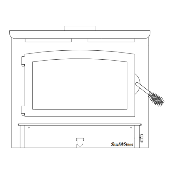
MODEL 74
NON-CATALYTIC UNIT
Buck Stove
FIREPLACE INSERT & FREESTANDING
FEATURES
PREPARATIONS
INSTALLATION
OPERATION
MAINTENANCE
SAFETY
SAFETY NOTICE
IF THIS HEATER IS NOT PROPERLY INSTALLED, A HOUSE FIRE MAY
RESULT. FOR YOUR SAFETY, FOLLOW THE INSTALLATION INSTRUCTIONS.
CONTACT THE AUTHORITY HAVING JURISDICTION (SUCH AS MUNICIPAL
BUILDING DEPARTMENT, FIRE DEPARTMENT, FIRE PREVENTION
BUREAU, etc.) CONSULT BEFORE INSTALLATION TO DETERMINE THE NEED
TO OBTAIN A PERMIT. KEEP THESE INSTRUCTIONS FOR FUTURE USE.
TESTED AND LISTED BY:
PFS/TECO, COTTAGE GROVE, WI
MANUFACTURED BY NEW BUCK CORPORATION
200 ETHAN ALLEN DRIVE
P.O. BOX 69
SPRUCE PINE, N.C. 28777
www.buckstove.com (828)-765-6144
Revised July 2020
Advertisement

Related Manuals for BuckMaster 74NC


Summary of Contents for BuckMaster 74NC
- Page 1 MODEL 74 NON-CATALYTIC UNIT Buck Stove FIREPLACE INSERT & FREESTANDING FEATURES PREPARATIONS INSTALLATION OPERATION MAINTENANCE SAFETY SAFETY NOTICE IF THIS HEATER IS NOT PROPERLY INSTALLED, A HOUSE FIRE MAY RESULT. FOR YOUR SAFETY, FOLLOW THE INSTALLATION INSTRUCTIONS. CONTACT THE AUTHORITY HAVING JURISDICTION (SUCH AS MUNICIPAL BUILDING DEPARTMENT, FIRE DEPARTMENT, FIRE PREVENTION BUREAU, etc.) CONSULT BEFORE INSTALLATION TO DETERMINE THE NEED TO OBTAIN A PERMIT.
- Page 3 TABLE OF CONTENTS Important Instructions ..............................2 Stove Identification ..............................3 SECTION I: Introduction ............................4 Type of wood and loading procedures ........................4 Chimney Heights ................................5 SECTION II: Masonry Insert Installation ........................6 Installation Preparation-Fireplace ..........................7 Mounting Trim Panels ..............................9 SECTION III: Pre-Fab Insert Installation ......................... 12 SECTION IV: Residential Freestanding Installation ....................
- Page 4 DAMAGE, BODILY INJURY OR EVEN DEATH. AVE THESE INSTRUCTIONS FOR FUTURE REFERENCES. The New Buck Corp. non-catalytic Model 74NC non-catalytic systems have been tested to UL • 1482 Standards and certified by PFS/TECO. Standard for Room Heaters, Solid Fuel Type.
- Page 5 EPA COMPLIANCE STATUS wood heater. This This manual describes installation and operation of the New Buck Corporation Model 74 heater meets the U.S. Environmental Protection Agency’s Emission limits for wood heaters and is in compliance with 2020 particulate emission standard. Under specific test conditions, this heater has been shown to deliver heat at rates ranging from approximately 13,300 to 52,400 BTU/hr for the Model 74.
- Page 6 CAUTION YOUR CHIMNEY MUST BE CORRECTLY SIZED. A CHIMNEY THAT IS TOO SMALL OR LARGE IN DIAMETER, OR TOO SHORT, CAN CAUSE YOUR STOVE TO SPILL SMOKE WHEN DOOR IS OPENED. SECTION I INTRODUCTION Your new MODEL 74 is a non-catalytic unit designed to meet the most stringent emissions standards without use of a catalytic combustor.
- Page 7 CHIMNEY HEIGHTS GREATER LESS THAN THAN 10 FT. 10 FT. 10 FT. 2 FT. 3 FT. 2 FT. 3 FT. METAL CHIMNEY 2 FT. MINIMUM HEIGHT ABOVE THE ROOF WITHIN 10 FT. HORIZONTALLY CHIMNEY “10 FT.” RULE (MINIMUM HEIGHTS) MASONRY CHIMNEY NOTE: MINIMUM CHIMNEY HEIGHT 15 FT.
- Page 8 SECTION II MASONRY INSERT INSTALLATION The Model 74 may be installed using an all masonry fireplace built in accordance with Uniform Building Code and National Fire Protection Association (NFPA). The first step in this type of installation is to determine acceptability of fireplace and chimney for use with a woodstove.
- Page 9 POSSIBLE TOOLS NEEDED FOR INSTALLATION If you decide to install your own stove, there are several hand tools you may need to do the job. If you do not already have them, they are readily available at most hardware stores. Caulking gun Large adjustable wrench (may not be needed) Drop cloths or newspapers...
- Page 10 SAFETY NOTICE If this appliance is not properly installed, a house fire may result. For your safety, follow the installation directions. Contact local building or fire officials about restrictions and installation inspection requirements in your area. OPTION (A) AIRTIGHT INSU- LATED CLEAN- STARTER PIPE SEAL TRIM PANELS AND UNDER...
- Page 11 INSTALLATION PROCEDURE (Use a chimney connector or a Listed Direct or Positive Connect) (See Page 8). POSITIONING HEATER When positioning heater, following conditions MUST be met! (See Figure 8). The front of damper opening must be positioned BEHIND rear edge of lintel to ensure proper draft. (See Figure 8).
- Page 12 NOTE: Mount top trim panel so that it sits in front of top of side trim panels. 9. Obtain brass trim kit provided with insert kit and slip over top and sides of trim panels. Top ends of brass may need to be trimmed to fit (See Figure 10).
- Page 13 CAUTION THE UNIT IS PAINTED WITH A SPECIALLY FORMULATED HIGH TEMPERATURE PAINT THAT CURES DURING THE FIRST TWO OR THREE FIRINGS. YOU MAY NOTICE A SLIGHT SMOKING EFFECT AND AN ODOR OF BURNING PAINT WHEN YOU BUILD THE FIRST FIRES. THIS IS NORMAL AND IS NOT A CAUSE FOR ALARM.
- Page 14 SECTION III PRE-FAB INSERT INSTALLATION The Model 74 has been tested with the following UL listed manufactured Pre-Fab Fireplaces: Heatilator Security Tempco Preway Marco Woodside Majestic The Model 74 will fit any of models that are large enough to accept them. NOTE: A full chimney liner is required in a Zero Clearance or pre-fab fireplace.
- Page 15 SECTION IV RESIDENTIAL FREESTANDING INSTALLATION Select an installation location that will give best airflow from front of heater to remainder of the home. PREPARING STOVE FOR INSTALLATION 1. Inspect unit for any obvious physical damage. 2. Plug power cord into a 115V AC outlet to test motor and fan. Do not run power cord under unit or in high traffic areas.
- Page 16 Chimney This model is designed for connection to any listed 2100º UL103 HT chimneys and parts. Follow chimneys manufacturer's instructions carefully. This room heater must be converted to (1) a chimney complying with the requirements for Type HT chimneys in the Standard for chimneys, Factory-Built, Residential, Type and Building Heating Appliance, UL 103, or (2) a code approved masonry chimney with a flue liner.
- Page 17 CAUTION SPECIAL METHODS ARE REQUIRED WHEN PASSING THROUGH A WALL OR CEILING. SEE INSTRUCTIONS AND BUILDING CODES. DO NOT CONNECT THIS UNIT TO A CHIMNEY FLUE SERVING ANOTHER APPLIANCE. DETERMINING CHIMNEY LOCATION A. CEILING EXIT (USING SINGLE WALL (minimum 24ga.) pipe and 2100° UL 103 HT type chimney system listed with manufacturer in this section of manual.) 1.
- Page 18 B. Wall Exit Into Metal Tee-Box 1. Mark plumb line on wall directly behind center of heater. (See Figure 15). NOTE: When using 24# ga. minimum blue or black steel pipe, maintain 18" between pipe and ceiling. (See Figure 15). NOTE: Floor protector must be under horizontal pipe exit (See Figure 18, Page 20).
- Page 19 C. Wall Exit Into Masonry Flue (Using Single Wall Pipe) 1. Before connecting these units to a masonry chimney, determine that masonry flue pass-through connector thimble meets NFPA-211 Code and local building codes and is a minimum of 18" from ceiling. If connector thimble does not meet these codes, the pass-through connector must be modified.
- Page 20 D. Ceiling Exit-Close Clearance 1. Suspend a plumb bob from ceiling above unit so that weight is hanging in center of flue exit (A small weight on a string will serve as a plumb bob). Mark ceiling where string is suspended to locate center of chimney hole. 2.
- Page 21 FINAL CHECK 1. Recheck specified clearances. 2. Remove all foreign material from firebox area. 3. Open primary air draft. 4. Plug power cord into a 115V AC outlet when using with optional motor. Do not run power cord under unit or in high traffic areas. 5.
- Page 22 CLEARANCES FOR MODEL 74 MINIMUM CLEARANCES TO COMBUSTIBLES RESIDENTIAL / SINGLE WALL CONNECTOR WITHOUT OPTIONAL CLOSE CLEARANCE SHIELDS AND PIPE SHIELD BACK WALL Figure 18 MODEL 74 25" 8" 10.5" 8" 8" 6" 20" 10” FULL LENGTH PIPE TO WALL NOTE: All clearances are to combustibles using single wall pipe without optional close clearance shields and pipe shield, minimum floor protector.
- Page 23 CLEARANCES FOR MODEL 74 MINIMUM CLEARANCES TO COMBUSTIBLES RESIDENTIAL / PERMANENTLY LOCATED MANUFACTURED HOME, DOUBLE WALL OR SHIELDED SINGLE WALL CONNECTOR WITH OPTIONAL CLOSE CLEARANCE SHIELDS AND PIPE SHIELD BACK WALL BACK WALL Figure 19 MODEL 74 23" 4" 6.5" 4"...
- Page 24 CLEARANCES FOR MODEL 74 MINIMUM CLEARANCES TO COMBUSTIBLES RESIDENTIAL / PERMANENTLY LOCATED MANUFACTURED HOME, DOUBLE WALL OR SHIELDED SINGLE WALL CONNECTOR WITHOUT OPTIONAL CLOSE CLEARANCE SHIELDS BACK WALL BACK WALL Figure 20 MODEL 74 25" 4" 6.5" 8" 8" 6" 20"...
- Page 25 Installation of (Optional) Close Clearance Shields and Pipe Shield 1. Taking close clearance side shields, hold up to side of stove leaving 1/4" gap between shield and top of stove and 13/16” rear sides of stove. 2. Make reference mark in center of pre-punched hole in top & bottom rear of shield. Drill two (2) 3/32"...
- Page 26 CLEARANCES FOR MODEL 74 ALCOVE INSTALLATION DOUBLE WALL OR SHIELDED SINGLE WALL CONNECTOR WITH OPTIONAL CLOSE CLEARANCE SHIELDS AND PIPE SHIELD BACK WALL BACK WALL BACK WALL Figure 22 MODEL 74 23" 4" 6.5" 84" 36" 8” 6” 20” NOTE: All clearances are to combustibles using double wall or shielded single wall pipe and optional close clearance shields and pipe shield only, minimum floor protector.
- Page 27 SECTION V FREESTANDING PERMANENTLY LOCATED MANUFACTURED HOME INSTALLATION Floor Protection: When installing freestanding heater, a floor protector must be used. Floor protector must be 3/8” minimum thickness non-combustible material or equivalent. How to use alternate materials and how to calculate equivalent thickness An easy means of determining if a proposed alternate floor protector meets requirements listed in the appliance manual is to follow this procedure: 1.
- Page 28 TOOLS FOR INSTALLATION This model is designed for connection to any 2100° UL 103 HT chimneys. Follow chimney manufacturers instructions carefully. Drop cloth, 3/32" Metal drill bit, 5/16" magnetic socket chuck adapter, 5/16" wrench (box or socket) or adjustable wrench, Jigsaw with masonry, metal and wood blades WARNING: DO NOT INSTALL IN A SLEEPING ROOM.
- Page 29 1. Select an installation location that will give best airflow from front of heater to remainder of home. 2. Place protective floor pad in position. For minimum floor protection (See Page 25). 3. Place unit on pad making sure minimum clearance specifications are met. For minimum clearance to combustibles (See Page 21, Page 22).
- Page 30 RAIN CAP RAIN CAP 24" min. 24" min. (610 mm) 36" TYP. (610 mm) 36" TYP. FLASHING FLASHING RADIATION SHIELD RADIATION SHIELD 20 FT. MAX. OUTSIDE AIR DUCT THROUGH FLOOR WHEN MOBLE HOME IS NOT UNDERPENNED OUTSIDE AIR DUCT THROUGH UNDERPENNED Figure 27 For ceiling exit using close clearance listed chimney 1.
- Page 31 4. Next, install a New Buck Corporation chimney connector to flue of heater or use 3 “ELL” brackets and secure to top of heater and pipe. 5. Using single wall chimney connector, connect heater to chimney by following manufacturer's installation instructions exactly. (See Figure 28). NOTE: CRIMPED END OF PIPE DOWN AND INSIDE OF PIPE BLOW IT.
- Page 32 FINAL CHECK 1. Recheck specified clearances. 2. Remove all foreign material from firebox area. 3. Open primary air draft. NOTE: Plug power cord into a 115 VAC outlet. (If optional motor is being used.) Route cord to prevent damage to cord insulation from heat and sharp objects. Keep cord out of way of traffic to prevent damage caused by tripping, etc.
- Page 33 SECTION VI WOOD HEATER SAFETY Certain safety hazards are inherent in any wood heater installation. You should be aware of these so that a safe and proper installation can be made. 1. FAULTY CHIMNEY: An older masonry chimney should be thoroughly checked to be sure there are no holes or weak spots which could allow sparks or hot gases to escape.
- Page 34 SECTION VII OPERATION/EFFICIENCY 1.“To maximize the efficiency of your wood stove make sure it is sized properly for the space you plan to heat. An oversized stove will burn and be forced to burn at a lower and dirtier burn rate. Consult with your dealer for sizing your stove correctly.
- Page 35 GUIDE TO THE DIFFERENT BURNING QUALITIES OF WOOD Type of Ease of Coaling Amount of Wood Starting Qualities Sparks Apple Poor Excellent Fair Good Beech Poor Good Birch Good Excellent Moderate Cherry Poor Excellent Cedar Excellent Poor Many Fair Good Very Few Hemlock Good...
- Page 36 SECTION VI MAINTENANCE DOOR GASKET REPLACEMENT (COLD HEATER) To replace deteriorated gaskets, follow these steps to ensure proper installation of gaskets. 1. Obtain proper gaskets and silicone glue from your local dealer. 2. Using pliers, remove any worn and deteriorated gaskets. 3.
- Page 37 MAINTENANCE BRICK LAYOUT TOP VIEW SIDE VIEW FIRE BLANKET BAFFLE BOARD NOTE: “This wood heater needs periodic inspection and repair for proper operation. It is against federal regulations to operate this wood heater in a manner inconsistent with operating instructions in this manual.” Page 35...
- Page 38 MAINTENANCE SECONDARY AIR TUBES REPLACEMENT (Replacing secondary air tubes) COLD STOVE Unplug heater from 115V AC outlet. Put drop cloth down. Empty ashes. Remove air tube. The (4) secondary air tubes are located in top of burn chamber. On right side of tubes you will find a cotter pin. To remove air tube remove cotter pin and slide tube to left, it will drop down, slide tube to right it should come out.
- Page 39 IDENTIFICATION DIAGRAM AND TUBE LOCATION Note: All tubes have a thru hole on one end of tube for cotter pin, this end of tube inserts into right side tube holder. FRONT FRONT 21 HOLES 15 HOLES 15 HOLES 17 HOLES &...
- Page 40 OPTIONAL MOTOR ASSEMBLY KIT INSTALLATION INSTRUCTIONS STEP 1: REMOVE ACCESS DOOR PANEL LOCATED AT BOTTOM OF UNIT. YOUR MOTOR ASSEMBLY COMES WITH A BRACKET ALREADY ATTACHED TO THE MOTOR. ALIGN THE HOLES IN MOTOR BRACKET WITH HOLES IN MOTOR MOUNT. SECURE BRACKET WITH TWO ½” HEX HEAD SCREWS PROVIDED.
- Page 41 MOTOR -THERMOSTAT-RHEOSTAT REPLACEMENT To replace Motor, Thermostat, Rheostat follow steps below. (OPT.)BLOWER KIT #MA5126715 STEP 1 STEP 3 VIEWED FROM ABOVE THERMOSTAT MOTOR BRACKET RHEOSTAT RIGHT SIDE ACCESS DOOR HEARTH SUPPORT PANEL MOTOR INDICATOR LABEL WITH BRACKET REMOVE REPLACE STEP 2 VIEWED FROM SIDE STAIN RELIEF RHEOSTAT...
- Page 42 MAINTENANCE CHECK CHIMNEY A. Chimney should be inspected twice a year. B. The chimney should be cleaned as necessary to remove creosote, soot, leaves, birds’ nests, etc. Before sweeping the chimney a few steps must be done. Put a drop cloth down. 1.
- Page 43 CLEANING THE HEATER A. The heater should not be cleaned with any type of detergent as most all detergents have an oil base and cannot be painted over. B. The heater should be lightly sanded with fine sandpaper or steel wool, then repainted or touched up with high temperature paint.
- Page 44 SECTION VIIII TROUBLESHOOTING PROBLEM POSSIBLE CAUSE SOLUTION Sluggish Heater Obstruction in chimney Check for and remove obstruction Improperly sealed trim kit or (a) Check trim kit gasketing direct connect kit seal to fireplace and gasket as necessary to seal unit and gasket under front bottom of stove, if needed.
- Page 45 TROUBLESHOOTING (Continued) PROBLEM POSSIBLE CAUSE SOLUTION High fuel consumption Improper regulation of draft (a) Close inlet air control as or inlet air much as possible to maintain desired heat output (b) Check gaskets, reinstall fiberglass gasketing round doors and glass as necessary Improper door fitting Check door gasket, check...
- Page 46 REPLACEMENT PARTS MODEL 74 NOTE: For replacement parts use only manufacturer’s specified parts. Description Quantity Part No. Door Gold MA912651GW Door Black MA912651GW Door Pewter MA912651PW Door Handle PO210092 Retrofit Door Bushing PO210102 Thin Spacer PO910104 Retrofit Door Handle Spacer PO21SPACER Retrofit Handle Latch PO910106...
- Page 47 NEW BUCK CORPORATION (NBC) "LIMITED WARRANTY" FOR THE BUCK STOVE PLEASE READ THIS WARRANTY CAREFULLY PRODUCTS COVERED This warranty covers the new Buck Stove heating unit, so long as it is owned by the original purchaser, including optional and standard accessories purchased at the same time, subject to terms, limitations, and conditions herein set out.
- Page 48 Page 46...
- Page 49 If for any reason you are dissatisfied with the suggested procedures, you may contact us in writing at: New Buck Corporation Customer Service Department P. O. Box 69 Spruce Pine, NC 28777 Email: info@buckstove.com CONDITIONS AND EXCLUSIONS (A) Replacement of parts may be in the form of new or fully reconditioned parts, at NBC's option.
Need help?
Do you have a question about the 74NC and is the answer not in the manual?
Questions and answers