
Subscribe to Our Youtube Channel
Related Manuals for Toshiba RAS-07EKH


Summary of Contents for Toshiba RAS-07EKH
- Page 1 FILE NO. A10-9508 SERVICE MANUAL AIR-CONDITIONER SPLIT WALL TYPE RAS-07EKH/RAS-07EAH RAS-09EKH/RAS-09EAH PRINTED IN JAPAN, Dec., 1995 S...
-
Page 2: Table Of Contents
3-3. Pipe Process Points ......................... 11 4. WIRING DIAGRAM ......................13 5. SPECIFICATIONS OF ELECTRICAL PARTS ..............14 5-1. RAS-07EKH/RAS-07EAH (Indoor Unit) ..................14 5-2. RAS-07EAH (Outdoor Unit) ......................14 5-3. RAS-09EAH (Outdoor Unit) ......................14 6. REFRIGERANT CYCLE DIAGRAM ................15 7. -
Page 3: Specifications
1. SPECIFICATIONS Model RAS-07EKH/EAH Item Heating Cooling Capacity 220V 230V 240V 220V 230V 240V 1.78 1.80 1.82 1.83 1.85 1.87 Btu/h 6070 6140 6210 6240 6310 6380 Phase Single Power source 220/230/240 Power consumption 560/570/580 490/500/510 Power factor 100/100/99 100/100/100... - Page 4 Model RAS-09EKH/EAH Item Cooling Heating Capacity 220V 230V 240V 220V 230V 240V 2.28 2.30 2.32 2.47 2.50 2.53 Btu/h 7780 7850 7920 8430 8530 8630 Phase Single Power source 220/230/240 Power consumption 740/750/760 670/680/690 Power factor 95/94/92 94/92/89 Running current 220V 230V 240V...
- Page 5 Note: *1 • Capacity is based on the following temperature conditions. JIS C9612-1994 Cooling Heating 27°C 20°C (DB) Indoor unit inlet air temperature (WB) 19°C – 35°C (DB) 7°C Outdoor unit inlet air temperature (WB) 24°C 6°C Note: *2 CHARGELESS •...
-
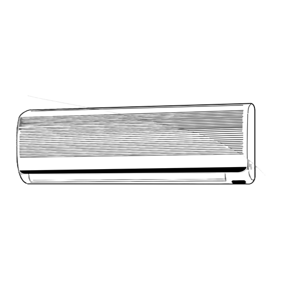
Page 6: Construction Views
2. CONSTRUCTION VIEWS 2-1. Indoor Unit RAS-07EKH RAS-09EKH Fig. 2-1 – 6 –... -
Page 7: Outdoor Unit
2-2. Outdoor Unit RAS-07EAH RAS-09EAH Fig. 2-2 – 7 –... -
Page 8: Caution In Installation
3. CAUTION IN INSTALLATION 3-1. Installation of Indoor Unit 3-1-1. Removing the Front Panel (1) Open the screw caps and remove the two screws (2) Close the screw caps as behind. securing the front panel. (3) Open the air outlet direction (up-down) louver hori- zontally by hand. - Page 9 (2) Insert the connective cable fully into the termi- (5) Fix the wiring cover, rear plate bushing and front nal block and secure it by screw tightly. panel on the indoor unit. (3) Secure the connective cable with the cord clamp. (4) Tightening torque should be 1.2 N.m (12 kgf.cm) Fig.
-
Page 10: Flaring
3-2. Flaring (2) Left-hand connection with piping When the piping runs to the left, be sure to use a tool 3-2-1. Pipe Cutting such as a pipe bender to bend the pipe. (1) Cut the pipe little by little advancing the blade of Note: pipe cutter slowly. -
Page 11: Pipe Process Points
Note: • Fine flaring work shows even brightness on the flared surface and uniform thickness of pipe. • Be sure to remove burrs to avoid unevenness on the flare face which will cause gas leaks. • Unsuccessful flaring work causes gas leaks, therefore rework it. - Page 12 (3) The radius of the pipe bend should be 100 mm or Note: more. • Insufficient tightening causes gas leaks. Over tightening results in cracks the flared surface. CAUTION: • Do not use the spanner from the beginning of tightening. Fig.
-
Page 13: Wiring Diagram
4. WIRING DIAGRAM RAS-07EKH/RAS-07EAH RAS-09EKH/RAS-09EAH Fig. 4-1 – 13 –... -
Page 14: Specifications Of Electrical Parts
5. SPECIFICATIONS OF ELECTRICAL PARTS 5-1. RAS-07EKH, RAS-09EKH (Indoor Unit) Parts name Type Specifications Output (Rated) 18W, 2 pole, 1 phase, 220 – 240V, 50 Hz MMF-200-18-2C White-Black Fan motor (For indoor) Winding resistance (Ω) Red-Black (at 20°C) 101.6 209.4... -
Page 15: Refrigerant Cycle Diagram
6. REFRIGERANT CYCLE DIAGRAM RAS-07EKH/RAS-07EAH RAS-09EKH/RAS-09EAH Fig. 6-1 Table 6-1 Standard pressure Surface temp. of heat Ambient temp. Fan speed exchanger P (kg/cm conditions DB/WB (indoor) 50Hz interchanging pipe T (°C) (°C) Model RAS-07EKH RAS-09EKH RAS-07EKH RAS-09EKH Indoor Outdoor Standard 12.6... -
Page 16: Micro-Computer Block Diagram
7. MICRO-COMPUTER BLOCK DIAGRAM Fig. 7-1 – 16 –... -
Page 17: Operation Descriptions
8. OPERATION DESCRIPTIONS 8-1. Names and Functions of Indicators and Controls on Indoor Unit 8-1-1. Display Panel The operating conditions are indicated below. Fig. 8-1 8-1-2. Control Panel Lift the front panel to perform control panel setting. (1) Opening the front panel 1) Push the PUSH on both lower corners of the front panel. - Page 18 (e) Fan speed button (FAN) • Push this button to select fan speed. • When you select AUTO, the fan speed is au- tomatically adjusted according to the room temperature. You can also manually select the desired fan speed from three settings. (A receiving beep is heard.) (f) Auto louver button (AUTO) •...
-
Page 19: Names And Functions Of Indicators On Remote Controller
8-3. Names and Functions of Indicators 8-4. Handling the Remote Controller on Remote Controller 8-4-1. Location of the Remote Controller (a) Transmission indicator Keep the remote controller where its signals can reach the receiver of the air conditioner (a distance of 7m is •... - Page 20 8-4-3. Replacing Batteries CAUTIONS: The remote controller uses two alkaline dry batteries (LR03). • The air conditioner will not operate if curtains (1) Remove the cover of the battery compartment at doors or other materials block the signal from the back of the remote controller by sliding it out the remote controller to the indoor unit.
-
Page 21: Automatic Operation
OPERATING MODE: Once you select the operating mode, the operating conditions are saved in the unit’s microcomputer memory. Thereafter, the air conditioner will start operating under the same conditions when you simply push the START/STOP button of the remote controller. 8-5. -
Page 22: Heating/Cooling/Fan Only Operation
8-6. Heating/Cooling/Fan Only Operation 8-6-1. Operation Steps Start • The OPERATION lamp (green) on the display panel of the indoor unit starts flashing. (1) Mode button • Select HEAT, COOL or FAN ONLY. (2) TEMP. button • Push the TEMP . button. •... -
Page 23: Dry Operation
8-7. Dry Operation 8-8. Timer Operation 8-7-1. Operation Steps 8-8-1. Operation Steps Start The timer-reserved time indicates the time remaining available. The time indicated on the remote controller • The OPERATION lamp (green) on the display changes accordingly. panel of the indoor unit starts flashing. (1) ON or OFF TIMER button (1) Mode button •... - Page 24 (2) ON TIMER (Stop ∅ ∅ ∅ ∅ ∅ Operation) CAUTION: The ON TIMER feature is useful when you wake up in the morning or when you return home. The When you select the timer operation, the remote air conditioner will automatically start operating controller automatically transmits the timer signal at the time set.
-
Page 25: Adjusting Air Flow Direction
8-9. ADJUSTING AIR FLOW DIRECTION (4) During cool and dry operation, change the air flow direction within the range indicated. 8-9-1. Adjustment of Vertical Air Flow Direction (1) When using the wireless auto louver, the air flow direction is automatically set to the desired posi- tion of the last time adjusted during operation. - Page 26 8-9-2. Adjusting the Horizontal Air Flow Direction Preparation: For the cooling or dry operation, move the vertical air flow louver downward using the SET button on the remote controller. (1) Take hold of the lever on the horizontal air flow grilles and move them to adjust the air flow direc- tion as required.
-
Page 27: Fan Only Operation
Table 8-2 Manual setting of FAN SPEED PREPARATION: Indication of FAN SPEED Air volume • When the power plug (or cord) is connected to EKH: AC 220/230/240V (50 Hz) outlet, the OP- ERATION (ON) lamp starts flashing, indicat- HIGH HIGH ing that power has been turned on (or that power failure occurred). -
Page 28: Heat Operation
8-12. HEAT Operation 8-13. ECONO. Mode (The remote control MODE button is set to the Heat (The remote controller’s ECONO. button is pushed position.) and ECONO. display is lit.) (1) Once the setting is made, the operation mode is (1) When the ECONO. button is pushed, the indoor memorized in the microcomputer so that the same unit operates quietly and mildly with controlling operation can be effected thereafter simply by... -
Page 29: Dry Operation
8-14. DRY Operation Table 8-3 Relation between room (The remote controller’s MODE button is set to the temp. (T ) and period period DRY position.) set temp. (T (1) In this mode, a microprocessor control lowers hu- > T 4 min. 6 min. -
Page 30: Cool Airflow Prevention Control
8-15-2. Current Limit Control and High-tempera- 8-16. Cool Airflow Prevention Control ture Limit Control (during Heating) (1) When control is performed with a thermostat, and When the load increases (overload) or the line volt- the thermostat is set to off, the indoor fan stops age drops during operation of the air conditioner, the operating, and restarts at the ultra low speed af- operating current increases, and when the power ca-... -
Page 31: Defrost Operation
8-17. Defrost Operation 8-17-3. Ending condition at Defrost Operation When the compressor current becomes 5.5A or more 8-17-1. Condition to Start the Defrost Operation during defrost operation, the defrost operation stops Defrost operation starts when the elapsed time is and the heat operation restarts. (The current sensor longer than 40 to 90 minutes, whichever specified. -
Page 32: Troubleshooting Chart
9. TROUBLESHOOTING CHART Troubleshooting Procedures: • Following details of “What to be prechecked first”, make sure of the basic items. • When there is no trouble corresponding to above, check in detail the faulty parts following “How to judge faulty parts by symptoms” later. 9-1. -
Page 33: Primary Judgement Of Trouble Sources
9-2. Primary Judgement of Trouble Sources 9-2-1. Role of Indoor Unit Controller 9-2-2. Display of Abnormalities and Judgement of the Abnormal Spots The indoor unit controller receives the operation com- mands from the remote control and assumes the fol- The indoor unit of this machine observes the opera- lowing functions. - Page 34 (2) Self-diagnosis with remote controller 2) Selecting ordinary mode With the indoor unit controller, self-diagnosis of Push the all clear button (ACL) on the rear protective circuit action can be done by turning bottom of the wireless remote control with a the remote controller operation into service mode, tip of pencil for more than 3 seconds.
- Page 35 <Self-diagnosis by check codes> 2) Remote control key operation under the ser- vice mode is conducted by ON/OFF or TEMP . 1) The self-diagnosis by the check codes is con- ducted under the block displays of item B-E. The remote control display by each key op- eration is varied as shown below.
- Page 36 Table 9-5 Block level Diagnosis function Judgement and action Check Check Air conditioner Block Symptom Condition code code status Indoor PC Thermo sensor Continued Indicated when • Check thermo sensor. board short/break. operation detected abnor- • If it is OK, check PC mal.
-
Page 37: Troubleshooting Flowcharts
9-3. Troubleshooting Flowcharts 9-3-1. Power cannot be Turned on (No Operation at All) <Preliminary checks> (1) Is the supply voltage normal? (2) Is the connection to the AC output O.K.? (3) Are the connection of the primary side and the secondary side of the power transformer inserted into the PC board? Color identification WHI : WHITE... - Page 38 9-3-2. Relay RY07, RY08 do not Operate. Louver is not controlled automatically. Note: • When wiring to the thermal fuse has been broken, the timer lamp and operation lamp will flash with 5 Hz. 9-3-3. Only the Indoor Fan does not Operate. <Preliminary checks>...
- Page 39 9-3-4. Compressor does not operate. (Indoor fan also does not turn.) < Preliminary checks > (1) Is the temperature set on the remote control higher than the room temperature in cool operation? (2) Is contact of the crossing wiring O.K.? <...
-
Page 40: How To Check The Remote Control (Including The Indoor Pc Board)
9-5. How to Check the Remote Control (Including the Indoor PC Board) – 40 –... - Page 41 9-5-1. How to check the PC board 2) The PC board consists of the following 4 parts: (1) Operating precautions a. Main PC board part: 1) When removing the front panel or the PC Power relay, indoor fan motor drive circuit and board, be sure to disconnect the power plug control circuit, C.P .U.
- Page 42 Procedure Check point (Symptom) Trouble cause Push the START/STOP button once to 1. The compressor does not operate. • The temperature of the Indoor set in operation mode. heat exchange unit is extremely low. 1.Setting the anti-resistor timer 2. The operation lamp flashes. •...
-
Page 43: Pc Board Layout
9-6. PC Board Layout Top view – 43 –... - Page 44 Bottom view – 44 –...
-
Page 45: Exploded Views And Parts List
10. EXPLODED VIEWS AND PARTS LIST 10-1. Indoor Unit Location Part Location Part Description Description 43005210 Front Panel (EKH) 43047331 Pipe, Delivery 43003218 Rear Plate 43047332 Pipe, Suction 43007963 Bush, Rear Plate, Right 43069858 Remote Controller 43007967 Lid, Rear Plate 43021794 Motor, Louver 43011503 Pipe Sealed 43070090 Hose, 3M, Drain... - Page 46 43033211 Capacitor, Film 43060794 Terminal-Block 43033213 Capacitor, ECQ-UV, 43097195 Tamper-Proof-Screw 0.1MFD, 250V 43069627 SS-Sensor, Thermostat 43055284 Toshiba Non Linear Resistor 43060023 Cord, Power 43032488 Posistor, 820HM 43082263 Screw-Driver 43060013 Fuse, Time Delay 43060007 Thermal Fuse Set 43060778 Terminal-Block 43068355 P .C. Board Assembly, Trans...
-
Page 47: Outdoor Unit
10-2. Outdoor unit Location Part Location Part Description Description 43019769 Guard, Fan 43049643 Rubber-Cushion 43020223 Fan, Propeller 43032441 Nipple, Drain 43005037 Front Cabinet 43019770 Stopper, Guard 43043548 Condenser 43069988 Holder, OL-Relay 43062194 Cover, E-Parts 43054400 Relay, Overload 43005038 Back Cabinet (RAS-07EAH) 43047491 Capillary Tube 1.5DIA 43054401 Relay, Overload... - Page 48 TOSHIBA CORPORATION 1–1, SHIBAURA 1– CHOME, MINATO – KU, TOKYO 105 – 01, JAPAN...
Need help?
Do you have a question about the RAS-07EKH and is the answer not in the manual?
Questions and answers